manuals.online logo
Brands
  1. Home
  2. •
  3. Brands
  4. •
  5. PVP Communications
  6. •
  7. Radio
  8. •
  9. PVP Communications Motor-One PV-HR-WW/XM User manual

PVP Communications Motor-One PV-HR-WW/XM User manual

Popular Radio manuals by other brands

Grundig G6 AVIATOR owner's manual

Grundig

Grundig G6 AVIATOR owner's manual

Makita DMR114 instruction manual

Makita

Makita DMR114 instruction manual

PURE Move R3 manual

PURE

PURE Move R3 manual

Motorola CP040 Detailed service manual

Motorola

Motorola CP040 Detailed service manual

Bosch GPB18V-5C Operating/safety instructions

Bosch

Bosch GPB18V-5C Operating/safety instructions

Ocean Digital WR-230 user manual

Ocean Digital

Ocean Digital WR-230 user manual

Realistic TRC-457 owner's manual

Realistic

Realistic TRC-457 owner's manual

Uniden AX 144 owner's manual

Uniden

Uniden AX 144 owner's manual

SIGNIFY EA2173 instruction manual

SIGNIFY

SIGNIFY EA2173 instruction manual

auna multimedia 10026443 user manual

auna multimedia

auna multimedia 10026443 user manual

GME TX680 instruction manual

GME

GME TX680 instruction manual

Motorola MTM5 00 Series Basic service manual

Motorola

Motorola MTM5 00 Series Basic service manual

Tivoli Audio ONE+ owner's manual

Tivoli Audio

Tivoli Audio ONE+ owner's manual

Sirius Satellite Radio SDVK1 installation guide

Sirius Satellite Radio

Sirius Satellite Radio SDVK1 installation guide

Sirius XM RAdio EDGE user guide

Sirius XM RAdio

Sirius XM RAdio EDGE user guide

Trevi XF 100 user guide

Trevi

Trevi XF 100 user guide

EisSound KBSound iSelect user manual

EisSound

EisSound KBSound iSelect user manual

Kirisun DM588-02 user manual

Kirisun

Kirisun DM588-02 user manual

manuals.online logo
manuals.online logoBrands
  • About & Mission
  • Contact us
  • Privacy Policy
  • Terms and Conditions

Copyright 2025 Manuals.Online. All Rights Reserved.

(**add red sleeve**)
wht
Shield
Shield 7 ft
wht
Shield
(7557 Cable)
7 ft
wht
4 ft (7557 Cable)
31
32
16
9
5
(7557 Cable)
Radio
PTT
PA
PTT
(NX)
(red)
(NX)
(black)
Shield
DT06-2S DT04-2P
DT06-2S DT04-2P wht
25
Remote PA
(solder side)
30
44
15
16
31
1
Radio PTT
Radio PTT
PA PTT 1
PA GND
black 18awg 48”
12 “
S10-7130
pwr/pair
gnd
ledg
led+
ledr
white
black
34
20
orange
green
red
19
18
17
Status
3A fuse
GND
+12V Battery or Ignition
red 18awg 60”
This document shall be considered PVP Communications, Inc. proprietary information and not be disclosed
to any third party without the prior written consent of PVP Communications, Inc.
RevDate Authorized Description
NC08/20/2010 MD Release
Check
Date: 08/20/2010
Sheet 1 of 1 Drawing No: PV-HR-WW/XM
Title: Motor Kit, Portable-Only
with WS320 Siren, G2 Wireless,
for Harley Motor, for trunk box install
Eng
10
11
38
39
8
chassis
Female (pins) DB44
(pin side)
16
31
1
30
44
15
Female (pins) DB44
Pwr
P7-5
(blk)
FH-106
DB44 (female pins)
Connector
SB
S10-7130 Cable
Z-3225 grommet
Drill 5/16”
1551 box
(See drawing PVMOD110-01
for Box Drilling)
Status LED
GRM219P grommet
L30022 lens cap
Drill 11/32”
N5040R-blk Boot
P7-5 switch
10179B Boot
Drill 1/4”
NOTES:
1) Install Status LED and Power/Pairing Switch in 1551 box as shown.
Assemble N5040R-blk cover to P7-5 switch with star washer and
10179B boot, L30022 lens cap to LED, cover LED with adhesive
sleeve, and install into GRM219P grommet.
2) Label as shown and include installation instructions
3) Ream DB44 (plastic) backshell with 1/2” Drill
4) Complete assembly includes Module PN: PVG2AS (not shown),
PTT Assy PN: PVPTT2-H02-DT and Harness Assembly PN: PV-HR-
WW-XMH
5) To panel mount Power/Pairing switch and Status LED on motor,
open 1551 box, remove switch and LED. Drill 1/4” hole to install P7-5
switch on motor, drill 11/32” hole to install LED grommet on motor
6) Include mounting HW noted in installation instructions
shield
8 ft (2/22
shielded) white
black
(tip) mh (blue/pink)
21
36
22
PTT
ML
MH
(ring) ptt (red/pink)
To Siren
(slv) ml (wht/pink)
1
2
1
2
1
2
1
2
4 ft (7557 Cable)
LABEL:
PV-HR-WW-XMH
Rev NC
CUT OUT AND MOUNT IN CONVENIENT LOCATION:
white
shield
black
Black sleeve
Red sleeve
red
black
Battery +
NOTE: Connect to BATTERY for “Manual Power On/Off Mode” or IGNITION (recommended) for
Chassis ( do NOT
connect to battery - )
Motorcycle PA PTT Button—Assemble to handlebar bracket
red
blk
Motorcycle Radio PTT Button—Assemble to handlebar bracket
ROAD KING - Mount MODULE inside rear radio trunk box
(for non-metal boxes). Never mount under the seat.
ELECTRA-GLIDE - Mount MODULE inside trunk box or
alternatively can be mounted directly under windshield and
inside fairing.
NOTE: Module MUST always mount above wiring harness
to allow water to run away from module. Improper
installation will void warranty.
NOTE: Mount transceiver module away from radio speakers.
black
PAIRING SWITCH - Secure box as desired inside trunk box or remove switch from box and panel mount to side of
trunk box (drill 1/4 inch hole) or for front mounted applications (Electra-glide) panel mount to fairing.
Status LED - Secure box as desired inside trunk box or remove LED from box and panel mount to side of trunk box
(drill 11/32 inch hole) or for front mounted applications (Electra-glide) panel mount to fairing.
QUESTIONS? call us at 800-584-4119 Monday
through Friday, 7AM to 4PM Pacific Time, USA.
PAIRING QUICK GUIDE
NOTE: All other Bluetooth devices in the immediate
area must be powered off.
1) Power off both devices. Press each PAIR switch until
LED goes to a solid color (2-3 seconds), then release.
2) Press and hold Motor PAIR switch until LED toggles
red-green-red-green, then release it and immediately:
3) Press and hold Shouldermic PAIR switch until LED
toggles red-green-red-green, then release.
4) After 10-15 seconds, a green pulse will confirm PAIR
is established.
INSTALLATION DIAGRAM
Included in this Kit:
1) Control Module: PVG2AS
2) Harness Assembly: PV-HR-WW-XMH
3) PTT Bracket: PVHARPTT-02
4) PTT Assembly: PVPTT2-H02-DT
5) Tie Wraps (15)
PTT Assembly
CONTROL
MODULE
Note: remove
screws to access
P.A. adjustments
Clockwise = Volume Up
Wires to 1/4 inch Harley Siren PA connector (pull back 1/4” jack and tie wrap to frame). Solder wires to back of connector as follows:
MIC+ (WHITE wire) - TIP ( blue/pink ) (2014 Models: Pink /Brown)
PTT (BLACK wire) - RING ( red/pink ) (2014 Models: Pink /Green)
GND (SHIELD wire) - SLEEVE ( white/pink ) (2014 Models: Pink /Black)
PA VOLUME:
Adjust helmet microphone PA transmit volume with a small flat screwdriver on the siren amplifier (to access, remove Philips head at siren amplifier).
NOTE: An additional gain adjust is available in the Control Module if additional volume adjustment is needed.
NOTE: When testing PA volume, make sure the siren speaker is directed to an open area to avoid improper feedback.
NOTE: When testing PA volume, make sure the helmet microphone is on axis (not rotated) and held close to the users mouth (within 1/4”).
PROGRAMMING
SYSTEM PAIRING:
The motor kit must be “paired” to a shouldermic. This creates a unique wireless link
between the shouldermic and the motor kit. Once a pairing procedure has been performed, the link is
“remembered” by both. A new pair may be established at any time, but until then, the shouldermic and the motor
kit will remain “faithful”, responding only to their mate. They will remember who their mate is—even after hav-
ing been powered off.
A) Connect helmet to shouldermic. The shouldermic will power on and the LED will begin to flash.
NOTE: Helmet must be connected to the shouldermic to power on.
B) Power off by pressing the pairing switch for 2-3 seconds until the LED transitions to a solid color, then re-
lease.
C) Activate the Motor Kit - the motor status LED will begin to flash. Manually power off the Motor Kit by press-
ing the pairing switch for 2-3 seconds until the status LED transitions to a solid color. Then release.
D) From the powered off condition, press the Motor Kit pairing switch for 7-9 seconds until the LED begins
toggling red-green-red-green, then release. The motor has powered on into pairing mode and is searching for a
mate.
E) Immediately after releasing the switch at the motor, press the pairing switch at the shouldermic (from the
powered off condition) for 7-9 seconds until the LED begins toggling red-green-red-green, then release. The
shouldermic has now powered on into pairing mode and searching for a mate.
Within 15 seconds both devices will display a green status LED pulse, indicating that they have been successfully
paired to each other.
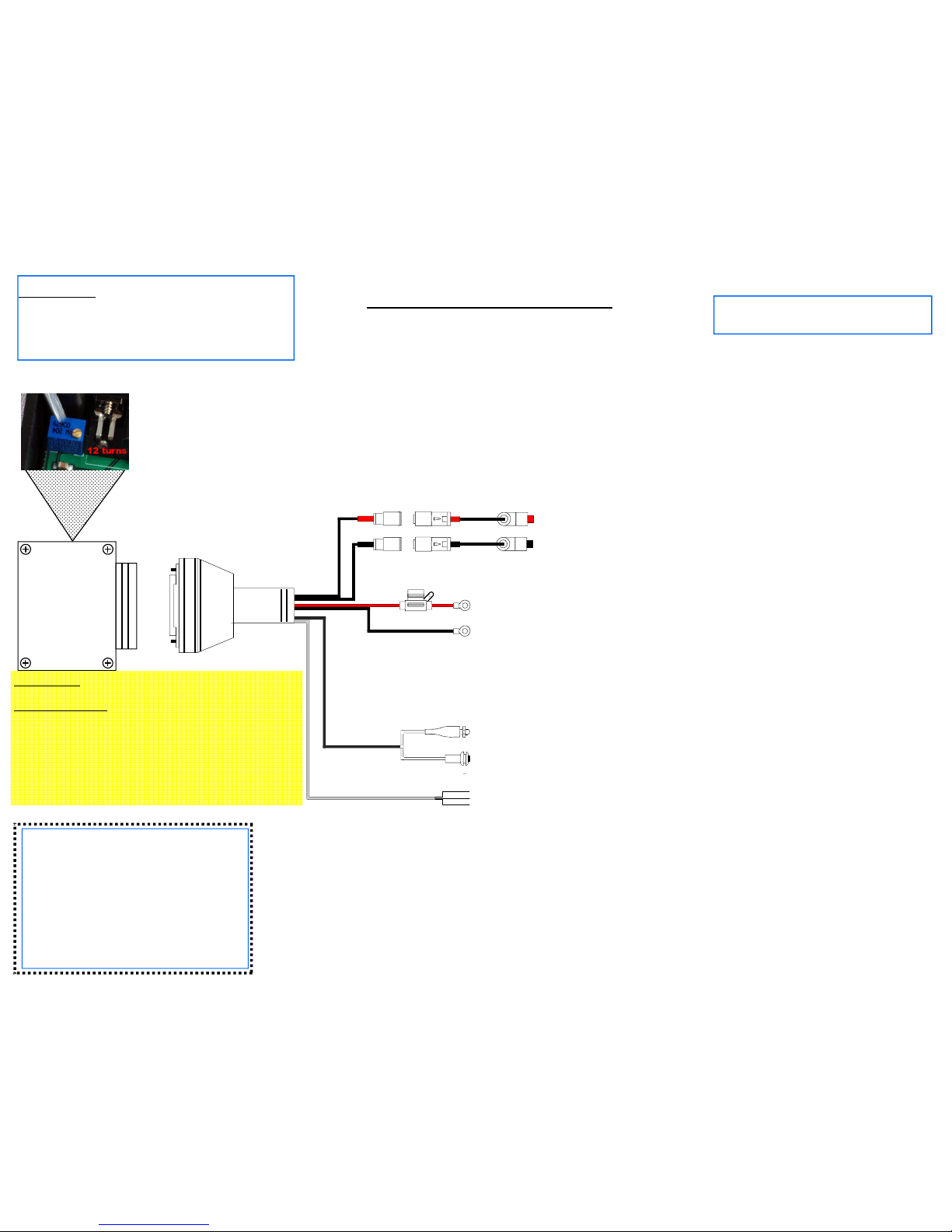
POWER ON/OFF MODES:
NOTE: Motor Kits are factory set for auto power-on mode where they will power on automatically whenever
12VDC is applied to the fused battery wire. It is recommended to connect the fused battery wire to motorcycle
ignition power and leave the Kit in the auto power-on mode.
The Motor Kit may be configured for “auto power-on” mode or “manual power-on” mode:
“Auto power-on” mode causes the motor kit to power on automatically whenever it is provided with battery
power through the fused battery wire.
“Manual power-on” mode allows the motor kit to be powered on/off manually with the “Pairing” switch. To
perform a manual power-on, make sure 12VDC is applied to the fused battery wire (it’s recommended to keep the
fused battery wire directly connected to the battery for use of this mode), then press and hold the Power switch for
2-3 seconds until the Status LED lights. Release the switch.
NOTE: Reverse the 2-3 second procedure to manually power off.
Changing power-on modes
Verify the Kit is powered on (LED flashing). Press the pairing switch quickly 5 times within one second to place
the kit in manual power-on mode. Press the pairing switch quickly 4 times within one second to place the kit in
auto power-on mode.
OPERATION
HELMET DISCONNECTED
1) Attach shouldermic to portable radio, turn the radio on.
2) Press shouldermic PTT switch to transmit.
NOTE: An additional PTT switch is located on the radio connector.
3) Receive audio will play at the shouldermic speaker.
HELMET ATTACHED
1) Attach headset to shouldermic.
2) The following will occur:
A) The shouldermic speaker will mute and portable radio will play at the helmet earphones.
B) The helmet microphone will now be activated when PTT switch is pressed.
C) The wireless transceiver will power-on (auto power-on mode) and the status LED will begin flashing.
NOTE: The shouldermic contains a rechargeable battery that powers the internal wireless transceiver, and should
be charged each day. Charger connects at the headset connector port.
MOTORCYCLE HANDLEBAR SWITCHES
When paired (see PAIRING procedure) and powered on (see POWER ON/OFF MODES), the shouldermic and
motor kit status LED’s will display a green pulse, allowing the following:
1) The black handlebar PTT switch will activate portable radio transmit using the helmet microphone.
2) The red handlebar PTT switch will activate PA broadcast using the helmet microphone.
NOTE: Any PTT switch can be used at any time.
QUESTIONS? call us at 800-584-4119 Monday through Friday, 7AM to 4PM Pacific Time, USA.
INSTALLATION and OPERATING INSTRUCTIONS
Motor-One™ Wireless Portable Radio Interface Kit with PA
Broadcast for Police Motorcycles
United States Patents: 7,062,301 6,311,052 7,203,525