Sheet: 2 of 11
PRODUCT NAME
MODEL NO.
Date: 7/26/2017
Rev: A
1201-10
Drawn: BDYE
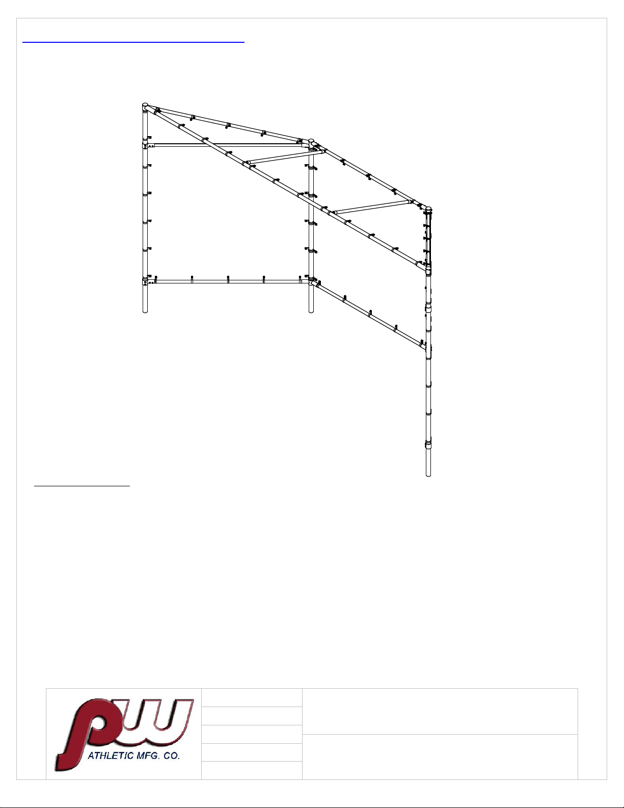
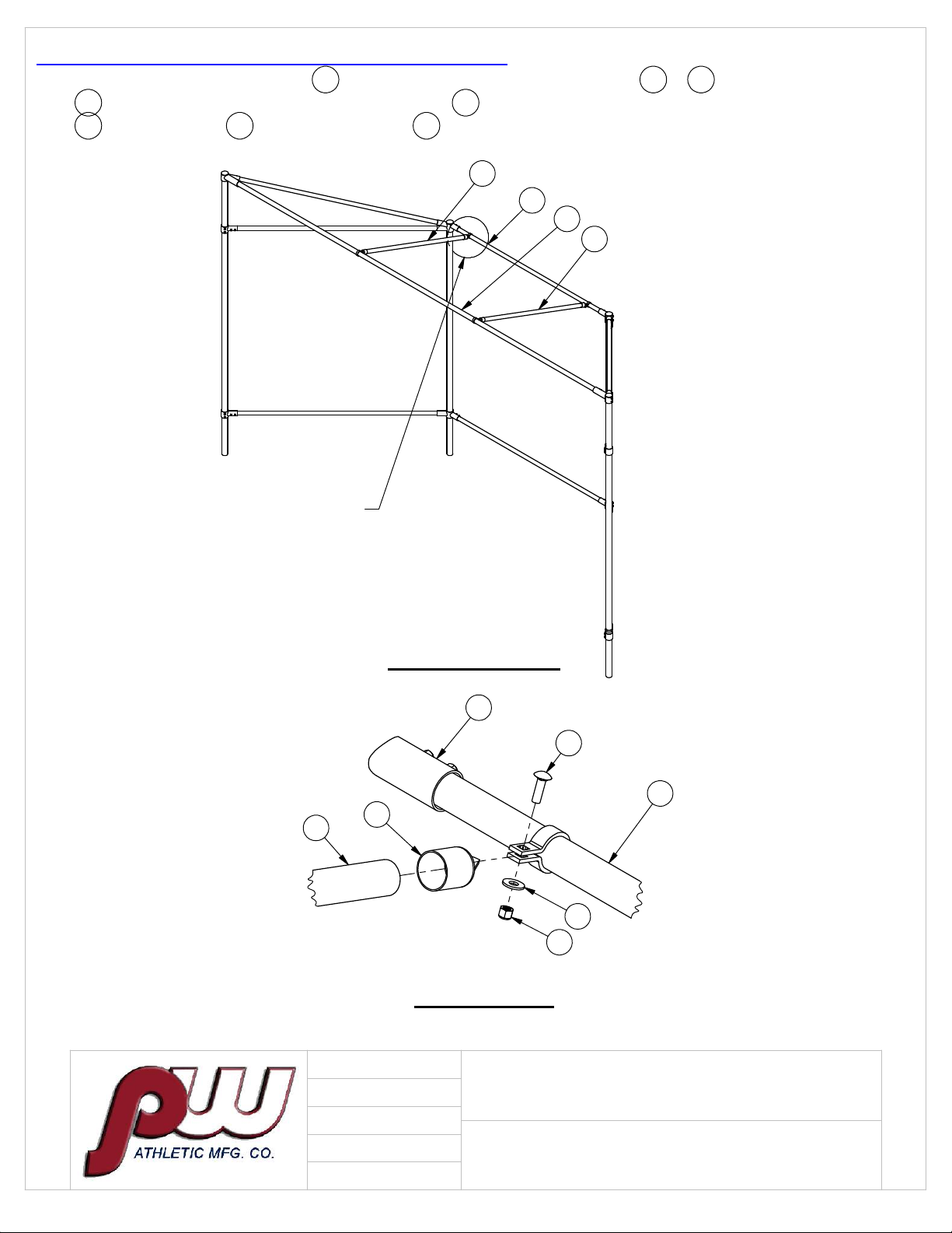
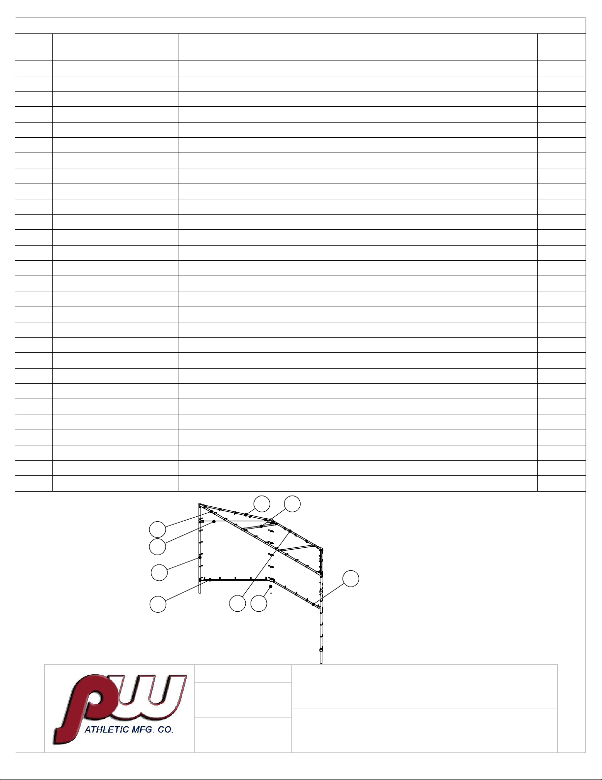
ECONOMY BACKSTOP
BOM
ITEM
NO. PART NUMBER DESCRIPTION QTY.
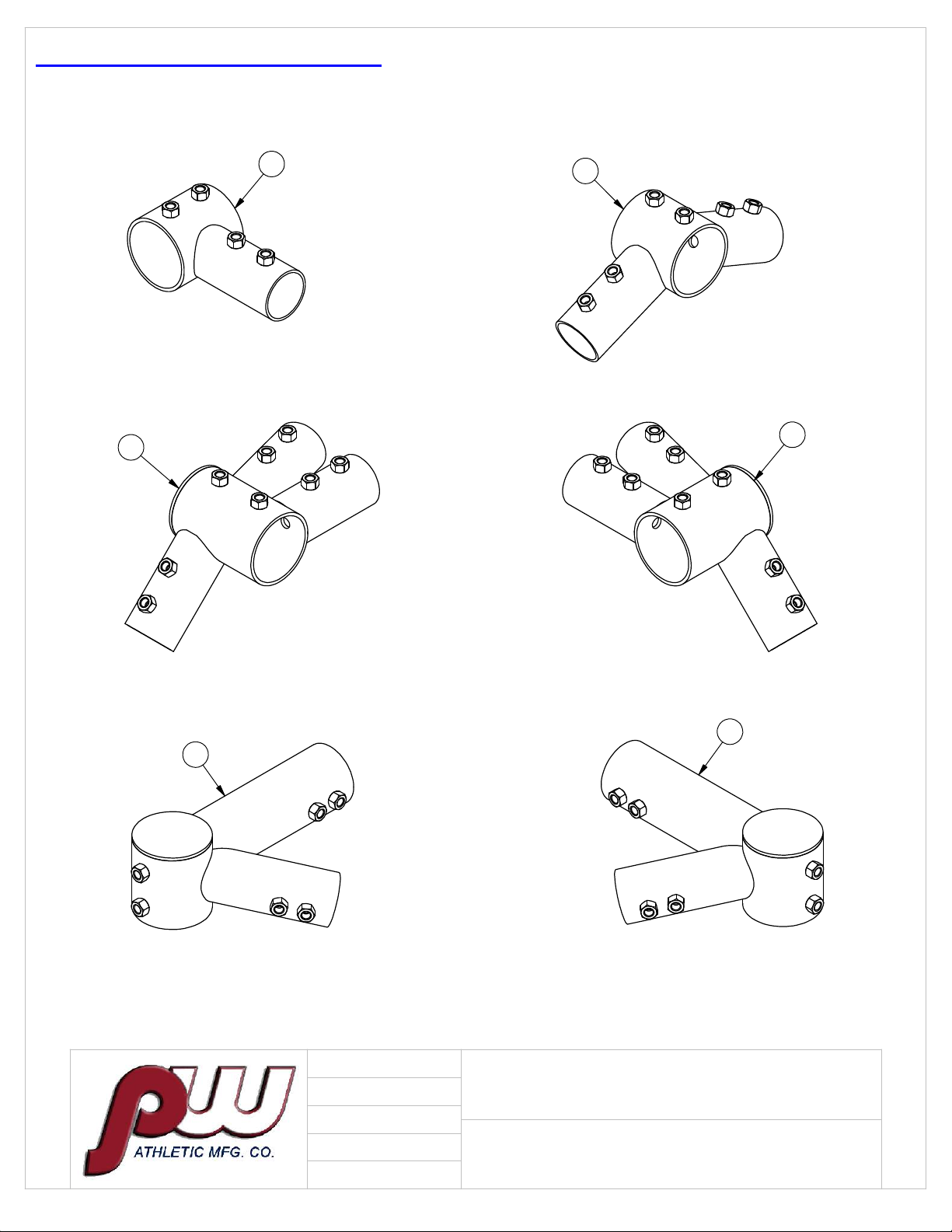
1 ASA-500-12AD-A1 12AD-A1 FITTING 4
2 ASA-502-12AD-A3 12AD-A3 FITTING 2
3 ASA-503-12AD-A4 12AD-A4 FITTING 1
4 ASA-504-12AD-A5 12AD-A5 FITTING 1
5 ASA-505-12AD-Z1 12AD-Z1 FITTING 1
6 ASA-506-12AD-Z2 12AD-Z2 FITTING 1
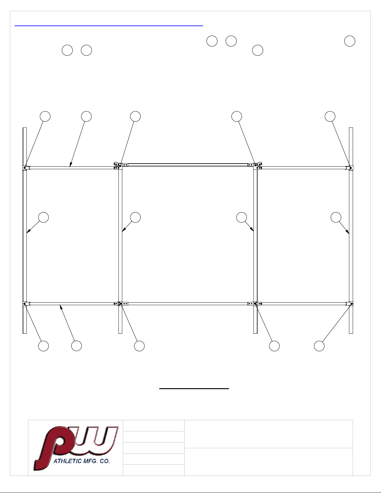
7 RT-003-1210-138-G FRONT VERTICAL POSTS 2-3/8" DIA. 2
8 RT-001-1210-114-G REAR VERTICAL POSTS 2-3/8" DIA. 2
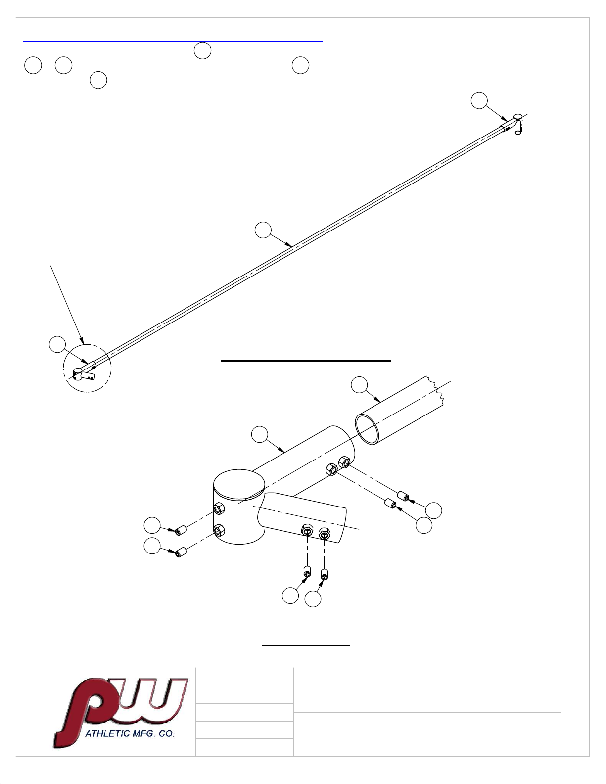
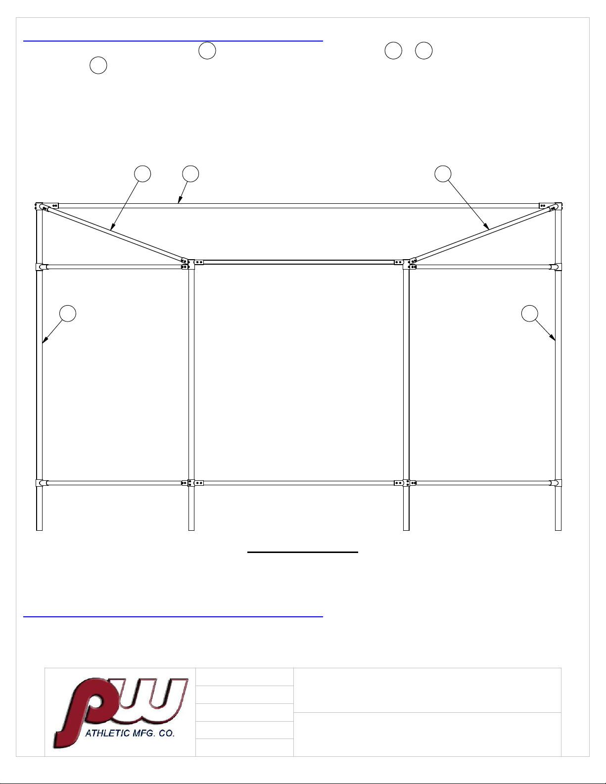
9 RT-002-1210-87-G BOTTOM HORIZONTAL RAILS 1-5/8" DIA. 6
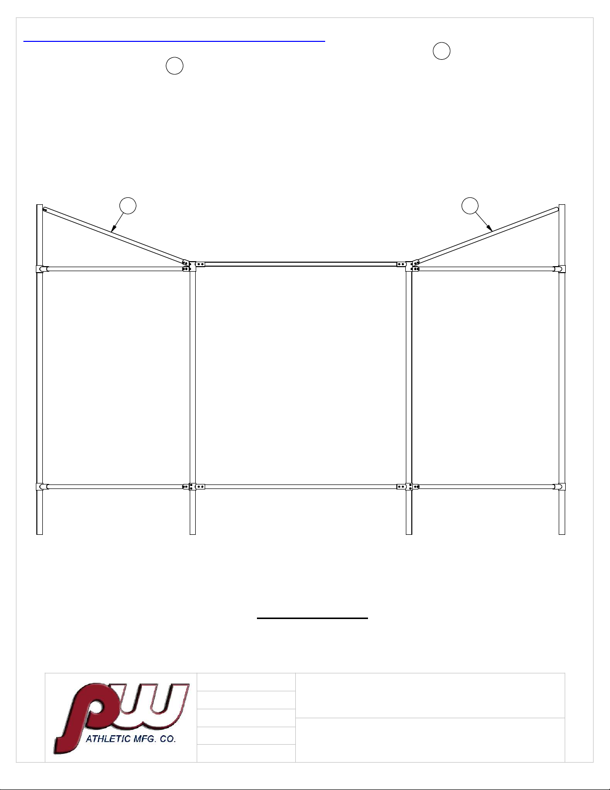
10 RT-004-1210-88.5-G TOP SIDE HOOD RAILS 1 7/8"DIA. 2
11 RT-005-1210-212.5-G HOOD CROSSBAR 1 7/8" DIA. 1
12 RT-006-1210-62.25-G CENTER HOOD SUPPORT 1 5/8"DIA. 2
13 HWSC3858 3/8 X 5/8 SET SCREW ZINC 56
14 HWFLWA38 3/8" USS FLAT WASHER 4
15 HWLN38 3/8"-16 LOCK NUT 4
16 HWCB38114 3/8-16 X 1 1/4 CARRIAGE BOLT ZINC (5-9/16 BRACE BANDS) 4
17 HWCB5161 5/16-18 X 1 CARRIAGE BOLT GRADE 2 ZINC 96
18 HWFLWA516 5/16 FLAT WASHER 96
19 HWLN516 5/16 NYLOK NUT ZINC 96
20 VCIRAILEND158 1 5/8 ID RAIL END 4
21 VCIBB163 1 5/8" BRACE BAND 2
22 VCIBB178 1 7/8" BRACE BAND 2
23 VCITEN238 2 3/8" TENSION BAND 38
24 VCITEN158 1 5/8" TENSION BAND 47
25 VCITEN178 1 7/8" TENSION BAND 11
26 8' TENSION BAR 4
27 10' TENSION BAR 2
28 #10 X 1/2 RD HD U - DRIVE SCREW ZINC 30
VCITBAR8
VCITBAR10
HWDS1012HWDS1012
9
10
7
12
9
11
9
9
8