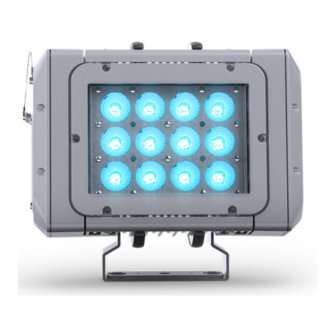
PXM PxArt+ 06 Track User manual

User manual

1 Description...................................................................................................3
2 Safety conditions........................................................................................4
3 Connectors and control elements...........................................................6
4 Information on version..............................................................................6
5 DMX connection.........................................................................................7
5.1 LOBAL Trac® AC 600 adapter..............................................................................7
5.2 The cross-section of the DMX LOBAL Trac® Pulse Control..............................7
6 Control..........................................................................................................8
6.1 Buttons.......................................................................................................................... 8
6.2 DMX signal................................................................................................................. 10
7 Cooperating with the PX277 con/gurator...........................................11
7.1 Available parameters...............................................................................................11
7.2 Scheme of the PX800-T menu in PX277..............................................................13
8 RDM – available parameters..................................................................14
9 Connection scheme.................................................................................16
10 Dimensions.............................................................................................17
11 Technical data........................................................................................18
Manufacturer reserves the right to make modications in order to improve device
operation.
!"#$%&
''!"#$
()*+,%-.
&'%'
,/0,
111 ,
23

1 Description
45),!+!,
,,6!7 666,
,!,!88445)+6!!3!
96+6,1!166,376+6
:,,,!6+6+ ;,,
!3+!,3!,9
,!!9376+62;+9
,6!<,,,!+69++6!
,+7, !1!,6
!3!6=+63=>icker free6+7?6
+9166,63!7
6!31661,+@4*(4A
93!!16!!
1!3!!!!6,1!!
!<,+6!,9+!6+
6, 6+66!6,+
,7> + +6,
16?
B+67345),!7*,*A!6,16
C7,96+61666,,,,6
6,+!6+6!
1
'

2 Safety conditions
D(+9+!+6,763
7!6!,
61+7,!!,,
76!!6,
)+D
2
!66
E+D
F6G!
E+D
45)+6,9
67
!,+
E+D
6
E+D
2!6
,
D
)645)945)!,+7 )
6+6167!366+67
4+66,!7997
!,+37+6
E61+!,!966+
6%H 6!16
6!3!+,
;,+6!,7
<7!666I
&

6!31!!7,'J1+! F
,71667,76!,7!+
6K 67361+/
;6!,!76!+6
:I9!+6,
61666,!,
,67:,>6,'1!
:!16!!3?
' 6!6!!+,6!
6,!,+
& ;63!,++7!96!!16
!6,6!
% 96!,!1617
)617!3163!,+
. !!697!+96!3!!
6!3!16,16H
6+66&H
- 16!,67
%

3 Connectors and control elements
4 Information on version
(1!6 ,!!+166
LLLM
L3/
L45)
L45)
L45)
L,+/
LH
LH
'L'H
&L&H
54NL
EENNLEE6
ML6+/
L+7
L
'L16
N36,
NN36,!
..,
+,,+
(+6!<,
,
!<,

5 DMX connection
!36!6@4*(4A7
+6@!!!6
5.1 LOBAL Trac® AC 600 adapter
5.2 The cross-section of the DMX LOBAL Trac®
Pulse Control
.
DMX contacts
MAINS POWER SUPPLY
neutral (on the opposite
side phase 3)
phase selection switch
phase 1 (on the opposite
side phase 2)
protective
DMX - (on the opposite
side DMX +)
3 1 2
phase 3
phase 1
phase 2
neutral
DMX +
mass (GND)
DMX -
POWER SUPPLY
DMX

6 Control
6.1 Buttons
6,6:!1616616++6
+63!,+6 663!
6,6<936,O *
,
)!+96!!+61+/
•6,L:O+6!!!
•)+3+L1O+6+6!<,
>BG:7?6I,3+6)
+
•66,6)+L!!
+6>7?,
•6)+6+!>61)+!
!933?L!!+,
•!,+6,,!L!!!+
,
6+6+6,9!6!!16
;!+6+6,
!<,6!!O+9,66,3
>,,,,,,?66!

;6+6!<,!166+
,3 F,9166,+6!9
6,, 6!!1+66+
!<,! 6+6!<,+1
6!,,+6,>+6!?
E66,96!!716!>!+
,!3?
-

6.2 DMX signal
6,!31)6/
•6L
•6L+6
8+6,,/
J6,, J6)+
!<+6
,
&%P %%
/ /
'P
/ /
.P
(+6!<,
Q %%
/ /
%Q
/ /
Q

7 Cooperating with the PX277 con/gurator
4,+6+!7+6..I+
>8+? ;116
!I61+,/)!!!+6
7>6+L%?!!3636
)+>+,,?
E66,!6I+961
7.1 Available parameters
DMX Addr.L6++6)!!6,!
+666+L%9
No Signal –636!3166)+!/
•Scene L+6!7!166)+!9
•On L16+6,Q9
•Off L,6!16,9
•oldL,+63)+9
No Signal TimeL!3,6!6)
+> L?9
SmoothL,66+)+3>OFFRLevel 1 – 4?9
Control modeL+,!/
•2ch DW BasicLDMX Addr.*)!!!66
,79
•2ch DW Adv.LDMX Addr.)!!!
+69

Driver temp.L6196+6!+,
6179
Module temp.L6196+6!+,
6,!1645)9
PWR time / ACT timeL,,R,+6+,9
Factory DefaultL7/
•)!!/
•S8+/*
◦8/
•S8+,/
•8,6/43'
•!/6)E(
Firmware versionL139
Serial Number L,

7.2 Scheme of the PX800-T menu in PX277
S*5D6+616)!!+62ch DW Adv.
+,!
'
PREV
DMX Addr.
001 000 (2ch) **
PREV
Channel: 1
Value: 0 *
ENTER
PX800-06
PxArt+ 06
ENTER
DMX Addr.
001 (2ch) *
NEXT
DMX Addr.
001 (2ch)
DMX Addr.
11 (2ch) *
NEXT
PX800-12
PxArt+ 12
PX800-18
PxArt+ 18
DMX Addr.
001 002 (2ch) *
NEXT
DMX Addr.
12 002 (2ch) *
ENTER
DMX Addr.
001 002 (2ch)
DMX Addr.
001 002 (2ch) **
NEXT
DMX Addr.
001 12 (2ch) **
ENTER
NEXT
No Signal
Off
NEXT
ENTER
No Signal
Off *
NEXT
No Signal
Scene *
NEXT
No Signal
On *
No Signal
Hold *
Channel: 1
Value: 128 *
NEXT
Channel: 1
Value: 2 *
Channel: 1
Value: 128
NEXT
Channel: 2
Value: 128
ENTER
PREV
No Signal Time
0.0 s *
No Signal Time
1.0 s *
NEXT
No Signal Time
10.0 s *
ENTER
No Signal Time
1.0 s
NEXT
Smooth
Off
NEXT
ENTER
NEXT
Control Mode
2ch DW Basic
NEXT
Smooth
Off *
Smooth
Level 1 *
NEXT
Smooth
Level 4 *
Control Mode
2ch DW Basic *
ENTER
NEXT
Control Mode
2ch DW Adv. *
Driver Temp.
40.9°C
NEXT
ENTER
Min Max Rec °C
24.6 41.8 41.8
ENTER
REC TEMP. RESET
Hold PREV + NEXT
NEXT
Module Temp.
67.8°C
ENTER
Min Max Rec °C
22.3 71.1 71.1
ENTER
REC TEMP. RESET
Hold PREV + NEXT
NEXT
PWR time 9h
ACT time 9h
ENTER
0d 09h 8m
0d 0 h 43m
NEXT
Factory Default
ENTER
Hold PREV + NEXT
NEXT
Firmware version
1.01
NEXT
Serial Number
20336110

8 RDM – available parameters
66)2) )17
17!,91662)
,,1! 6,7,+
36,!3 62),3+
,!3,7+,,!+6
42),!76 /
,, ) )
8T*25)U25528 % !,
2552U)582;;*S % !!!
,
)5J;5U;SF* ,+6!3
8*FE25UJ528;*SU4(54 I,136!3
)U))2588N F )+!!6!3
;)5S;FVN
!3!IW
1/
!I>3?
!!I>3?
)5JU*)54U
)58 !3!9 + ,
STFT252U4(54 ,!9
+ ,
)5J;5U4(54N
!!!3!W
;!!
!3!+'
8;;6
&

,, ) )
F*2VU)5FT48 - !3!+
528*S4;VN 5 ),!
528*S4;VU
)582;;*S 5 !!3!
,!
85S8*2U)5F;S;;*S ,6!
,
85S8*2UJ4T5 ,
8**BU*FFRRR'R&N ,6+
S*U8;@S4U*FFR*SRB4)R8
N 636!3166
)+!
S*8U;5N &) !3,16)
+!>L?
S*8U85S5UN +66
S*8U85S5UN +66
852;4UST(52 ' !3,
N!,
%

9 Connection scheme
3-phase GL BAL Trac®
Pulse Control bus-bar
end feed
power supply cable
DMX wire (2 wires in screen)
GL BAL Trac® GAC600 adapter
DMX+ DMX-
GND

10 Dimensions
Ø 92
134
225
284
.

ø148
191
252 61
229 (WW - Wall Washer version)
11 Technical data
!"
!#$%"
!%"
&'(&)* +,
-'
!
!
!
./0& %)

&&* ,$,$,$1,$/.23'1%,4$""22
3%',4
& #51%6364
&**)&7 58
9:' (;
0<$90<
*&&
* =.>?.& @
&A&&)* *&$& B$)
*)
!(B*
!(#B*
!(1B*
)*)!%
&!;
)*)!%
&!
)*)!%
&!1
N36,
NN,:!16EE>EE6?66
O!+67>!,?L36
!,
-

!"#$9
)542;*S*F*SF*2;V
X",!71
!"#$%&9''!"#$
1!6!/
Product name: RR
Product code:
,6:,61+!!916,!
!!/
S5S%-/%&
S5S&./
S5S&/
S5S;5/-'
S5S'/
5S%-/%
5S&./
5S&/-
5S;5/-
5S'/.
!,6:,61+!3/
R%RT5);25;J5*FB55T2*5S24;5SS)*FB5*TS;4Y6
66G!!:,
16553
&R'RT5);25;J5*FB55T2*5S24;5SS)*FB5*TS;4F7&
66,616,8+,+,7>?
16553
&R'%RT5);25;J5*FB55T2*5S24;5SS)*FB5*TS;4F7&
66,616,8+6,+36,
:,!+!163+,
,+$
This manual suits for next models
3
Table of contents
Other PXM Spotlight manuals
Popular Spotlight manuals by other brands

Knightsbridge
Knightsbridge EMTWINIP Installation & maintenance manual

ANDlight
ANDlight VOLUMES Series manual

Vision & Control
Vision & Control SLB-500-W5K7-P-SL Instructions for use

Bohle
Bohle Verifix TwinLED operating instructions

hepco & becker
hepco & becker 731665 quick start guide

brennenstuhl
brennenstuhl LUFOS 420 operating instructions