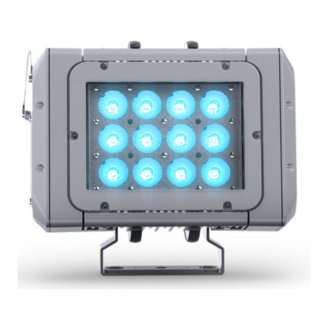
PXM PxArt+ 06 Wall User manual

User manual

1 Description...................................................................................................3
2 Safety conditions........................................................................................4
3 Connectors and control elements...........................................................6
4 Information on version..............................................................................6
5 Control..........................................................................................................7
5.1 Buttons.......................................................................................................................... 7
5.2 D X signal................................................................................................................... 9
6 Cooperating with the PX277 con'gurator...........................................10
6.1 Available parameters...............................................................................................10
6.2 Scheme of the PX800-W menu in PX277.............................................................12
7 RD – available parameters..................................................................13
8 D X signal connecting...........................................................................15
9 ounting...................................................................................................15
10 Connection scheme..............................................................................16
11 Dimensions.............................................................................................17
12 Technical data........................................................................................18
Manufacturer reserves the right to make modications in order to improve device
operation.
!"#$%&
''!"#$
()*+,%-.
&'%'
,/0,
111 ,
23

1 Description
45),!+!,
,,6!7 6686,
,!,8!899445)+68!!38!8
88:6+68,18!1686,376+6
;,,,!6+6+ <,,
!3+8!8,83!,:8
,!!:376+682<88+:
,6!=,8,,!+6:++6!
,+78, !881!8,6
!3!68>+63>?icker free86+7@6
8+:1686,63!7
6!3866!61,!!8761
1!3!!!8!86,1!!
!=,+6!8,:+!6+
6, 6+668!6,8+
,7
A+678345),!7*,*B!6,16
C887,:6+616866,,,,6
6,8+!86+6!88
1
'

2 Safety conditions
D(+:88+!+6,763
7!6!8,
61+7,!!,,
876!8!6,
)+D
2
!66
+D
E6F!
+D
45)+6,:
67
!,+
+D
6
+D
2!68
,
D
)645):45)88!,+7 )
6+681678!38686+67
4+66,8!7:88:7
!,+37+6
61+!,8!:66+
86%G 688!8816
6!38!+,
<8,+6!8,78
=7!6866H
&

6!381!!87,'I1+! E
8,71667,78868!,7!+
6J 687361+/
<6!,!76!+6
;H8:88!+68,
68816866,88!,
,67;,?6,'1!
;!16!8!38@
' 68!86!8!+,868!
6,!,+
& <63!,++78!8:6!8!16
8!86,868!
% :6!,!16817
)88617!38163!,+
. !!68:87!+:6!3!!
6!388!816,16G
6+66&G
- 16!,867
%

3 Connectors and control elements
4 Information on version
(1!86 ,!!+166
KKKL
K3/
K45)
K45)
K45)
K,+/
KG
KG
'K'G
&K&G
54MK8
MMK6
LK6+8/
K+7
K8
'K16
M36,
MM36!,
..,
+,,+88
(+6!=,
,
!=,

5 Control
5.1 Buttons
6,6;!161686186++6
+63!8,+6 6638!
6,6=8:36,N8 *
,
)!+:6!!+61+/
•6,K;8N8+6!!8!
•)+83+K1N8+6+6!=,
?AF;87@6H,83+6)
+
•66,86)+K!!
+6?87@,
•6)+86+!?61)+!
!:383@K!!+,
•!,+6,,!K!!!+
,
86+6+6,8:!6!!16
8 <!+6+68,
!=,6!!N8+:,66,3
?,,,,,,@686!
.

<86+6!=,!81686+
,3 E,:166,+68!:
68,, 6!!1+686+
!=,!8 6+6!=,+18
6!,,+6,?+6!8@
66,:6!!7186!?8!+
,!3@

5.2 DM signal
6,88!31)86/
•6K8
•6K+6
9+6,,/
I6,, I6)+
!=+68
,
&%O %%
/ /
'O
/ /
.O
(+6!=,
P %%
/ /
%P
/ /
P
-

6 Cooperating with the P 277 con'gurator
4,+886+!788+6..8H+
?9+@ <18816
!H61+,/)!!8!+6
7?6+K%@!!386368
)+?+,,8@
66,88!68H+:61
6.1 Available parameters
DMX Addr.K86++6)!!68,!
+6866+K%:
No Signal –636!38166)+!/
•Scene K+68!7!166)+!:
•On K186+6,P:
•Off K8,6!16,:
•oldK,+63)+:
No Signal TimeK!388,6!86)
+? K@:
SmoothK,686+)+3?OFFQLevel 1 – 4@:
Control modeK+,!8/
•2ch DW BasicKDMX Addr.*)!!!66
,87:
•2ch DW Adv.KDMX Addr.)!!8!
+6:

Driver temp.K61:6+6!8+,
617:
Module temp.K61:6+6!8+,
6,!1645):
PWR time / ACT timeK,,Q,+6+,:
Factory DefaultK87/
•)!!/
•R9+/*
◦98/
•R9+,/
•9,6/43'
•!/86)(8
Firmware versionK13:
Serial Number K,

6.2 Scheme of the P 800-W menu in P 277
R*5D6+8616)!!+62ch DW Adv.
+,!
PREV
DMX Addr.
001 000 (2ch) **
PREV
Channel: 1
Value: 0 *
ENTER
PX800-06
PxArt+ 06
ENTER
DMX Addr.
001 (2ch) *
NEXT
DMX Addr.
001 (2ch)
DMX Addr.
11 (2ch) *
NEXT
PX800-12
PxArt+ 12
PX800-18
PxArt+ 18
DMX Addr.
001 002 (2ch) *
NEXT
DMX Addr.
12 002 (2ch) *
ENTER
DMX Addr.
001 002 (2ch)
DMX Addr.
001 002 (2ch) **
NEXT
DMX Addr.
001 12 (2ch) **
ENTER
NEXT
No Signal
Off
NEXT
ENTER
No Signal
Off *
NEXT
No Signal
Scene *
NEXT
No Signal
On *
No Signal
Hold *
Channel: 1
Value: 128 *
NEXT
Channel: 1
Value: 2 *
Channel: 1
Value: 128
NEXT
Channel: 2
Value: 128
ENTER
PREV
No Signal Time
0.0 s *
No Signal Time
1.0 s *
NEXT
No Signal Time
10.0 s *
ENTER
No Signal Time
1.0 s
NEXT
Smooth
Off
NEXT
ENTER
NEXT
Control Mode
2ch DW Basic
NEXT
Smooth
Off *
Smooth
Level 1 *
NEXT
Smooth
Level 4 *
Control Mode
2ch DW Basic *
ENTER
NEXT
Control Mode
2ch DW Adv. *
Driver Temp.
40.9°C
NEXT
ENTER
Min Max Rec °C
24.6 41.8 41.8
ENTER
REC TEMP. RESET
Hold PREV + NEXT
NEXT
Module Temp.
67.8°C
ENTER
Min Max Rec °C
22.3 71.1 71.1
ENTER
REC TEMP. RESET
Hold PREV + NEXT
NEXT
PWR time 9h
ACT time 9h
ENTER
0d 09h 8m
0d 0 h 43m
NEXT
Factory Default
ENTER
Hold PREV + NEXT
NEXT
Firmware version
1.01
NEXT
Serial Number
20336110

7 RDM – available parameters
66)2)8 )817
17!,:1662)88
,,1!8 6,7,+
8368,!38 62),3+
8,!38,7+,,!+68
42),!76 /
,, ) )8
9S*25)T25529 % !,
2552T)592<<*R % !8!!
,
)5I<5T<RE* ,88+6!38
9*E25TI529<*RT4(54 H,136!38
)T))2599M E )+!!6!38
<)5R<EUM
!38!H8V
1/
!H8?3@
!!H8?3@
)5IT*)54T
)59 !38!8: + ,
RSES252T4(54 ,8!8:
+ ,
)5I<5T4(54M
!!!38!8V
<!!
!38!8+'
9<<868
'

,, ) )8
E*2UT)5ES49 - !38!+
529*R4<UM 5 ),!
529*R4<UT
)592<<*R 5 !8!3!
,!
95R9*2T)5E<R<<*R ,68!
,
95R9*2TI4S5 ,
9**AT*EEQQQ'Q&M 8,6+
R*T9<WR4T*EEQ*RQA4)Q9
M 636!38166
)+!
R*9T<5M &) !388,16)
+!?K@
R*9T95R5TM +8668
R*9T95R5TM +8668
952<4TRS(52 ' !38,
M!,
&

8 DM signal connecting
,88!6):1686+
688 6,66886!88!
6DMX6:!6,6DMX6)
83?!+,1@
<66!386):6,K
*6,6!88!6>DMX +>!>DMX->,
DMX IN
-+
GND
CORRECT
DMX-512 input DMX-512 output
DMX IN
-+
GND
WRONG
DMX-512 input DMX-512 output
DMX IN
-+
GND
CONNECTING THE TERMINATOR
DMX-512 input 120 Ohm
9 Mounting
6,:H866,?6@61 6
,6!76,61
%
we sja COB MONO
we sja MONO
we sja DW
183
308
Ř87
121
121
121
90
107
67
121
252
185
Ø92
279
262
200
213
Ø149
Ø122
256239 (we sja WW - Wallwashe )
239 (we sja WW - Wallwashe )

10 Connection scheme
L N PE GND DMX- DMX+ L N PE GND DMX- DMX+ L N PE GND DMX- DMX+
'I
)8
)
'!386
,
?*6,@

11 Dimensions
we sja COB MONO
we sja MONO
we sja DW
183
308
Ř87
121
121
121
90
107
67
121
252
185
Ø92
279
262
200
213
Ř149
Ř122
256
239
we sja COB MONO
we sja MONO
we sja DW
183
308
Ř87
121
121
121
90
107
67
121
252
185
Ø92
279
262
200
213
Ø149
Ø122
256239 (we sja WW - Wallwashe )
239 (WW - Wallwashe ve sion)
.

we sja COB MONO
we sja MONO
we sja DW
183
308
Ř87
121
121
121
90
107
67
121
252
185
Ø92
279
262
200
213
Ø149
Ø122
256 (WW - Wallwashe ve sion)
239 (we sja WW - Wallwashe )
12 Technical data
!
!"#$
!$
%&'%() *+
,&
!
!
!
-./% $(
%%) +#+#+#0+#.-12&0$+3#11
2$&+3

% "40$5253
%))(%6 47
89& ':
/;#8/;
)%%
) (%
%<%%() )%#% =#(
)(
!'$=)
!':=)
!'=)
()(!$
%!:
()(!
%!
()(!":
%!0
M36,
MM,;!16?6@866
N8!+67?!,@K36
!,
-

!"#$:
)542<*R*E*RE*2<U
X",!71
!"#$%&:''!"#$
1!86!8/
Product name: QQ
Product code:
,6;,61+!!:16,!
!!/
R5R%-/%&
R5R&./
R5R&/
R5R<5/-'
R5R'/
5R%-/%
5R&./
5R&/-
5R<5/-
5R'/.
!,6;,61+!83/
Q%QS5)<25<I5*EA55S2*5R24<5RR)*EA5*SR<4Y6
8686F!888!88;,
165538
&Q'QS5)<25<I5*EA55S2*5R24<5RR)*EA5*SR<4E7&
66,616,9+8,+88,7?8@
165538
&Q'%QS5)<25<I5*EA55S2*5R24<5RR)*EA5*SR<4E7&
66,616,9+6,+36,88
;,!+!1683+,
,+$
This manual suits for next models
3
Table of contents
Other PXM Spotlight manuals
Popular Spotlight manuals by other brands

Renkforce
Renkforce Cadiz operating instructions

Altman
Altman AFS-500 Installation & user manual

LIVARNO
LIVARNO Z31171 Assembly, operating and safety instructions

Hoftronic
Hoftronic BEND DUO 4409135 user manual

Robert Juliat
Robert Juliat SULLI 305LF quick start guide

Flash butrym
Flash butrym LEDSPOT10W instruction manual