PYROTEC PY 12 H User manual

Instruction Manual –Kilns up to 1320°C
PY 12 H –PY 290 HS
ST 35 H –ST 250 HD

2
Konformitätserklärung
Declaration of CE Conformity
Hiermit erklären wir, dass die nachfolgend bezeichneten Geräte mit der
Niederspannungsrichtlinie 73/23/EWG übereinstimmen:
The manufacturer herewith declares that the following products comply with the Low Voltage
Directive 73/23/EWG:
Alle elektrisch beheizten Brennöfen:
All electrical heated kilns:
PY12 H - PY290 HS
ST35 H - ST 250 HD
Mit Seriennummern >20000
With serial numbers >2000
Angewandte nationale Normen:
The following norms were consulted to assess conformity:
VDE 0100
VDE 0700 Teile 1 und 244
VDE 0700 Teil 500 (EN 50106)
Hersteller: PYROTEC Brennofenbau GmbH
Manufacturer D-49074 Osnabrück, Ziegelstraße 32b
www.pyrotec-gmbh.de
Osnabrück, 04.07.2019
Peer Lichtenberg, Geschäftsführer

3
Instruction Manual
For all models of the series STUDIO 1260°C and PROFITHERM 1320°C
Table of Contents page:
General Information 4
Safety Precautions 4
Installation of the kiln 4
Controller 5
Electrical Connection 5
First Firing 5
Operation of the Kiln 6
Maintenance 6
Repairs 7
Warranty conditions 8
Faults and their likely causes 8
Test report 9
Please follow the instructions for the installation and observe the safety information
for the operation of the kiln!
_______________________________________________________________________
Technical details are subject to change.

4
General Information
This instruction manual introduces you to your PYROTEC-kiln. Please take the time to read
the instructions carefully before commissioning the device. Please also pay attention to the
separate controller instructions.
Safety Information
When operating an electrically heated kiln for temperatures up to 1320°C (2408°F), it is
absolutely necessary to observe the following safety instructions:
•Install and operate the kiln only in appropriate rooms (see the section for the installation of
the kiln below).
•The electrical connection (power outlet, fuse) must be installed or checked by a qualified
electrician before commissioning (see page 11: electrical connection).
•Do not place inflammable materials in or on the kiln!
•Never heat up higher than the manufacturer’s recommendations for glazes and clay to
prevent damage to the kiln and ware.
•CAUTION: Do not touch the kiln shell and lid during the firing (risk of burns!).
•Open the lid only after the ware has cooled down.
•Pull the power plug before cleaning and servicing the kiln.
•The electronic controller simplifies the operation of the kiln and improves the
reproducibility of the firing process. To prevent overheating, it is recommended to
monitor the end phase of the firing in case the kiln or the controller is defective.
•Do not use extension cables!
Installation of the Kiln
Make sure that in public buildings only authorized persons have access to the kiln and the
controller. Manipulating the controller can cause damage to the ware and kiln.
Garages and furnace rooms are inadmissible locations because of fire risk.
The installation site must be well ventilated, dry and sufficiently large.
For improved ventilation, the exhaust air can be removed from the kiln via BYPASS system.
The required BYPASS-connector can be ordered as an optional accessory. The exhaust air
is dissipated through a flexible aluminum tube. The tube is connected to the BYPASS and
installed at a rising gradient. If the tube passes through a wall, the surrounding area must
consist of heat-resistant material.
The ground must be even (for stability), have a temperature stability up to 75°C and be able
to support the kiln’s weight (including the ware).
The surrounding walls and the ceiling must consist of non-flammable material. Surrounding
surfaces not meeting these requirements must be covered with fire-retardant insolation. In
this case, the kiln must have a minimum distance of 50 cm to the walls and 90 cm to the
ceiling. The minimum distance to non-flammable walls must be at least 30 cm to avoid heat
accumulation.
Do not place inflammable or temperature sensitive objects on the kiln.

5
Controller
Attach the controller to the wall next to the kiln at a minimum
distance of 30 cm. (In some models, it is mounted directly
on the kiln with the appropriate holder.) Install the wall
mounting according to the instruction manual for the
controller. The controller is connected to the kiln’s control
box with a multipolar plug. Be aware that the plug can be
inserted with ease only in one position!
The connection is secured with the retaining clip.
Do not let the power cable or the controller cable come into
contact with the kiln shell or the lid during the firing!
Electrical Connection
According to the VDE (German electrotechnology association), PYROTEC-kilns belong to the
protection class I. Electrical safety is provided primarily by the protective earth connection.
Therefore, the mains supply must be checked or installed by a qualified electrician before
commissioning the kiln. Be sure that the wire cross section is sufficiently dimensioned, and
the corresponding fuse has the proper size. The necessary technical data is found on the
type plate on the kiln’s control box.
The wall outlet must be easily accessible in order to be able to disconnect the kiln at any time
from the power grid. Do not connect an additional electrical load to this outlet!
Make sure that this power outlet is equipped with its own fuse with sufficient breaking
capacity.
It is imperative that the kiln is connected to the power supply without an extension cable.
Power cables of any length are available at low additional costs when ordering the kiln.
First Firing
During commissioning, the kiln must be operated with kiln shelves but without ware, using a
firing program with a long heating time or slow rise in temperature. We recommend a curve of
180°C per hour to 1000°C and a heating time of 3 hours. During this firing, residual moisture
evaporates from the insulation and the shelves. Additionally, the heating elements build up a
protective oxide layer, which results in a longer service life.
During the program, the contactor can be heard switching on and off. Unpleasant odors can
develop during the first two to three firings due to organic binder burnout in the insulation
material.
As a result of the very high temperature differences, fine cracks appear in the fire bricks.
They can appear already during the first firing. They have no influence on the firing process.

6
Operation of the Kiln
PYROTEC-kilns have a maximal application temperature between 1100°C and 1320°C,
depending on the model. In most cases, the maximal firing temperature will depend on the
characteristics of the ware and be limited to lower values. When in doubt, always use the
lower limit temperature.
Fire only approved raw materials and glazes in your kiln. When in doubt, consult your dealer.
Distribute the pieces you want to fire evenly in the kiln.
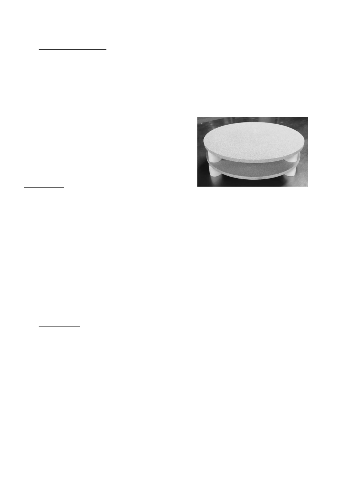
Use kiln shelves and props for optimal use of space.
Make sure that the props are positioned directly on top
of each other on every level for even weight
distribution to prevent cracks or deformation of the
shelves (see picture).
Biscuit Firing
During biscuit firing, raw ceramic pieces may touch each other. They can be placed directly
on the shelves. Large, flat bowls or tiles are fired in horizontal position on the shelves to
avoid distortions. Leave enough space between the shelves (bigger shelves need a greater
distance!). Sufficient space for air circulation is required for even temperature distribution.
Glaze Firing
During glaze firing, glazed ceramic pieces must not come into contact with each other or the
inside of the kiln or the glaze layers will fuse. For a glaze firing, place metal or ceramic
spacers underneath the glazed pieces to prevent glaze from sticking to the shelves. It is also
recommended to coat the shelves with kiln wash, which makes it easier to remove glaze
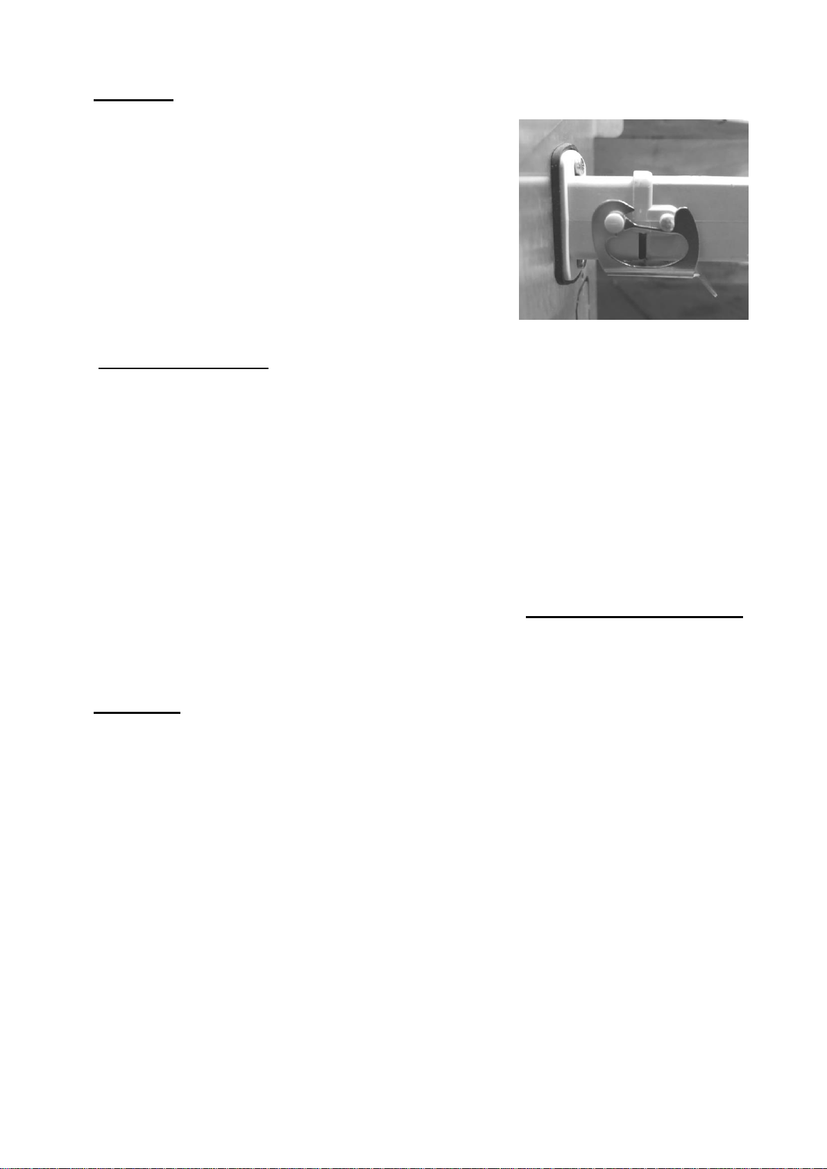
residues from the shelves. Kilns lids equipped with a latch should be buckled down during the
firing to avoid deformation of the lid.
Maintenance
It is recommended to have the electrical system checked by a specialist at regular intervals
(every 4 years).
The power plug must be disconnected before cleaning or servicing the kiln.
Check the interior wall for glaze residues before every firing. Remove glaze residues
immediately from the fire bricks. High thermal stress can lead to different expansion of the
heating elements. After the burn-in, the heating elements show the greatest shrinkage and
they can be retightened carefully (first, pull out the power plug, let the heating elements cool
down and then retighten the heating elements, if necessary).
Always make sure that the heating elements are resting in their designated grooves. If
a part of a heating element protrudes from the groove or is about to fall out, which indicates
the approaching end of its service life, it can be pushed back into the groove (risk of
breakage!). The shrinkage is dependent on several factors, among others on the firing
frequency and the final temperature as well as firings with glaze.

7
The insulation material of this kiln shows a significant shrinkage after
several firings. It is recommended to tighten the kiln shell with a
screwdriver or a spanner from time to time (see picture).
Repairs
CAUTION: Repairs shall only be performed by authorized specialists
(electrician/electrical engineer)!
1) Checking the heating elements (kiln temperature must be below 50°C)
-Start cold kiln with 100% power (see instructions for controller).
-Power off after 20 seconds.
-Unplug the kiln from the power source.
-Open the kiln and test the temperature of each element by touching it with a moist
sponge.
-Cold heating elements are defective and must be replaced.
2) Replacing heating elements
-Remove the screws on the control box cover on the kiln.
-Loosen the connecting screws at the ends of the heating element with two 8 mm
spanners and remove them.
-Cut off the looped ends of the heating element.
-Remove the element pins from the grooves in the kiln chamber.
-Remove the defective element carefully from the groove and pull out the ends towards
the kiln chamber.
-Clean the grooves carefully (use a vacuum cleaner).
-Insert the new element into the grooves and push the ends outward through the bore
hole into the control box of the kiln.
-Shorten the ends of the element to the appropriate length, bend them into a loop and
connect them with the set screws to the electrical supply.
-The screws must be tightened firmly in order to get maximal contact pressure and low
transfer resistance.
-Remount cover.
ATTENTION: Evaporating oil can cause unpleasant odors during the first firing with the new
heating elements.

8
3) Replacing the thermocouple
-Remove control box cover on the kiln.
-Remove locking wire.
-Loosen connection screws and remove thermocouple.
-When connecting the new thermocouple make sure that the polarity is correct:
PtRh-Pt element Type-S
NiCr-Ni element Type-K
red wire to (+) port
white wire to (-) port
green wire to (-) port
-Secure the new thermocouple with locking wire.
Warranty conditions
We provide a guarantee of 3 years from date of purchase on flawless manufacture and
function of every PYROTEC-kiln. Heating elements and thermocouple are parts subject to
wear and therefore not included in the guarantee. Additionally, the manufacturer is not liable
for damages resulting from improper handling of the kiln and ware.
ATTENTION: the fire bricks of the lining are exposed to strong temperature fluctuations
which can cause hairline cracks. This process is normal and does not compromise the
function of the kiln. Therefore, it is not a reason for complaint. For the register of warranty
claims please send us the information on the type plate and a copy of the bill from the dealer.
Faults and their likely causes:
Fault
Likely causes
Kiln does not heat up
kiln lid is not closed correctly
lid safety switch is out of adjustment
Contactor is defective
Thermocouple is defective (replace, see page 14)
Kiln does not or too slowly
reach final temperature
A heating element is defective (test, see page 13)
In kilns with three-phase power connection, a fuse has
blown in the meter box
Heating elements are failing due to old age (replace, see
page 13)
Kiln shuts down before
reaching final temperature
Short-term power failure
Controller is defective (contact your dealer)
Kiln shuts down immediately
Thermocouple is defective
compensating cable to the thermocouple is defective
When troubleshooting, please also consult the controller instructions.
Technical details are subject to change.

9
PRÜFPROTOKOLL / TESTREPORT
Serien-Nr /Serial-No: ________________
Ofenmodell/Kiln Model : ________________
Stromaufnahme/Current Intensity : L1 = A
L2 = A
L3 = A
Schutzleiterwiderstand /PE-resistance RSL = m
Isolationswiderstand /Insulation Resistance RISO > M
Ersatzableitstrom /PE - Current IEA = mA
Thermoelement korrekter Sitz /Thermocouple OK :
Deckelschalterfunktion /Function of Safetyswitch :
Osnabrück, .............................. .........................................................................
Datum /Date Unterschrift/Signature
_eng_betrieb_ofen.doc 19.11.19
This manual suits for next models
3
Table of contents