Q-Lab Q-SUN Xe-2 User manual

QUICK SET UP GUIDE LX-5085-QS
Revision Date
15 Jun 2022
Q-SUN Xe-2
Xenon Test Chambers

Table of Contents
1. Specications, Classications, Symbols (Jun 2022) ..........3
2. Safety Information .................................................................5
2.1 Heat and Electrical Shock Hazards (Jun 2022)..................5
2.2 Ultraviolet and Infrared Hazards (Nov 2020) ......................8
3. General Description (Apr 2022) ............................................9
4. Operating Environment ....................................................... 10
4.1 Suitable Environments (May 2020)................................... 10
4.2 Unsuitable Environments (Mar 2019) ............................... 11
5. Uncrating (Mar 2022) ...........................................................13
6. Setup..................................................................................... 18
6.1 Dimensions and Space Requirements (Mar 2022)...........18
6.2 Electrical (Jun 2022).........................................................19
6.3 Water (Mar 2022)..............................................................20
6.4 Lantern and Lamp (Jun 2022) ..........................................27
7. Start Up .................................................................................33
7.1 Specimen Mounting (May 2020) .......................................33
7.2 Power On ..........................................................................33
7.3 Main Controller Operation (Apr 2022) ...............................34
8. Warranty (Feb 2014) .............................................................37
9. Repair and Tester Support (Feb 2014)................................38
Section Table of Contents
2

3
1. Specications, Classications, Symbols (Jun 2022)
Specications, Classications
●The recommended ambient operating temperature and relative humidity (RH) for the Q-SUN®Xe-2 tester is 23 ± 5 °C
and 50 ± 25% RH.
●The maximum ambient operating temperature and humidity is 40 °C and 80% relative humidity.
●Temperatures outside the recommended range may cause chamber temperature and/or humidity faults.
●Transportation and Storage Temperature: -40 °C to 80 °C.
●Installation Category: Category II for transient over-voltages.
●Pollution Control: Pollution Degree 2.
●Sound Pressure Level: Sound Pressure Level does not exceed 75 dBA.
●Altitude: 2000 meters or less.
●Operation: Continuous Rating.
●Supply Connection: Permanently connected or plug/socket connection (industrial type per IEC 6309 or twist lock type
in North America).
●External Disconnect: Required for all connections.
●External Over-Current Protection: Must be rated for not more than 40 A (USA, Canada) or 64 A (Europe).
●Short Circuit Current Rating (SCCR): 1000 A.
Section 1. Specications, Classications, Symbols

Section 1. Specications, Classications, Symbols
4
Symbols
Electrical Shock Hazard
Hot Surfaces Hazard
Attention
Finger/Hand Crushing Hazard
Local waste & recycling regulations per the WEEE Directive
2002/96/EC on Waste Electrical and Electronic Equipment

Section 2. Safety Information
5
2. Safety Information
Q-Lab accepts no responsibility for the consequences if the user fails to comply with the instructions in this operating
manual. Q-Lab will accept responsibility for defective parts or components only if the machinery was defective at the time
that the tester was shipped.
●This manual does not claim to address potential safety issues, if any, associated with the use of this product.
●It is the responsibility of the user of this manual to establish appropriate safety and health practices, and to
determine the applicability of regulatory limitations prior to use.
●If the equipment is used in a manner not specied by the manufacturer, the protection provided by the equipment
safety devices may be impaired.
●The Q-SUN meets the European Low Voltage Directive 2014/35/EU and complies with the requirements of
EN 61010-1: 2010 (Third Edition), “Safety of Electrical Equipment for Measurement, Control and Laboratory Use”.
●The Q-SUN meets the European Electromagnetic Directive 2014/30/EC and complies with the requirements of
EN 55011:2007 Radiated and Conducted Emissions – class A.
●Use only parts that have been supplied or recommended by Q-Lab.
2.1 Heat and Electrical Shock Hazards (Jun 2022)
Warning Labels
●Warning: If the equipment is used in a manner not specied by the manufacturer, the protection provided by the
equipment may be impaired.
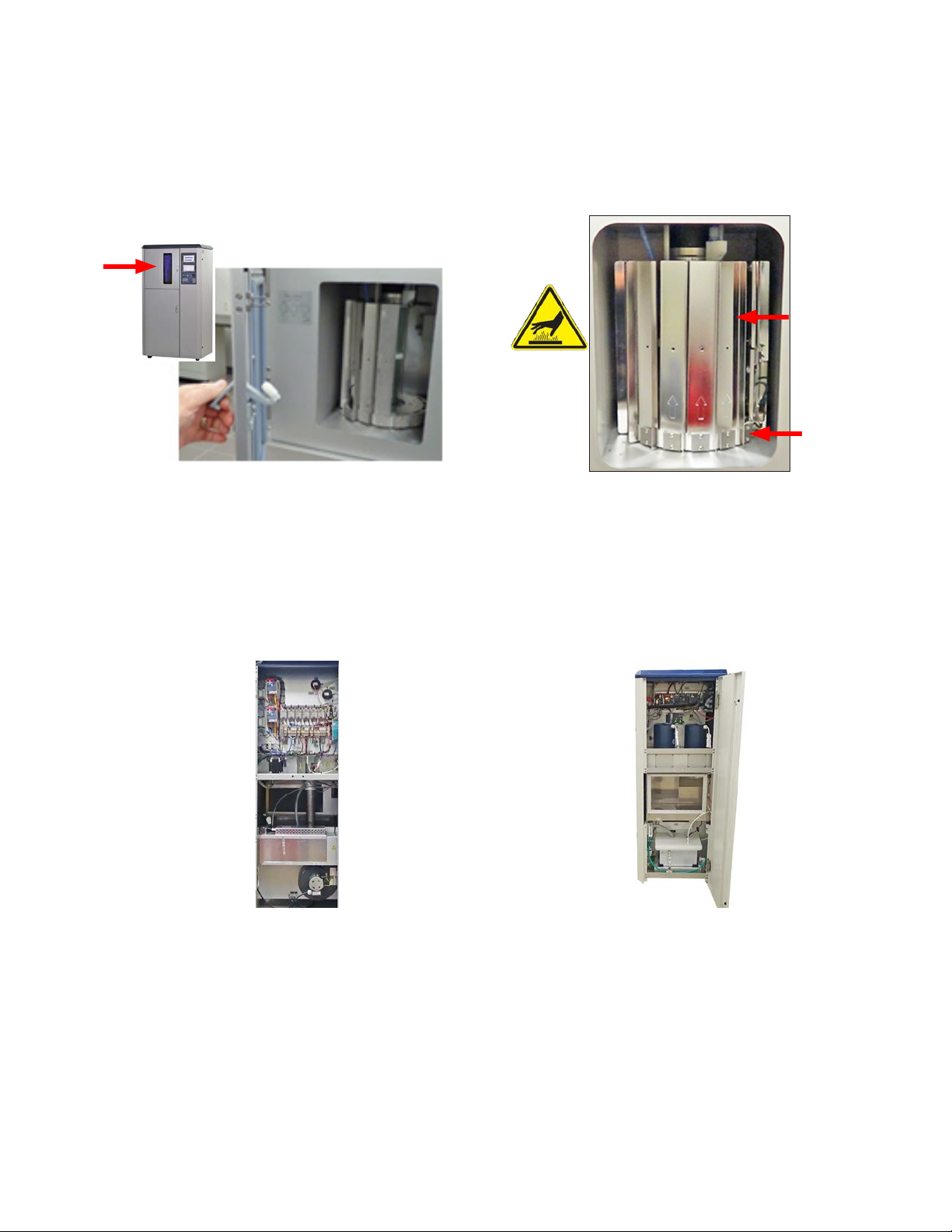
●Doors (Figure 2.1a) provide access to tester interior spaces containing heat generating and/or electrical
components.
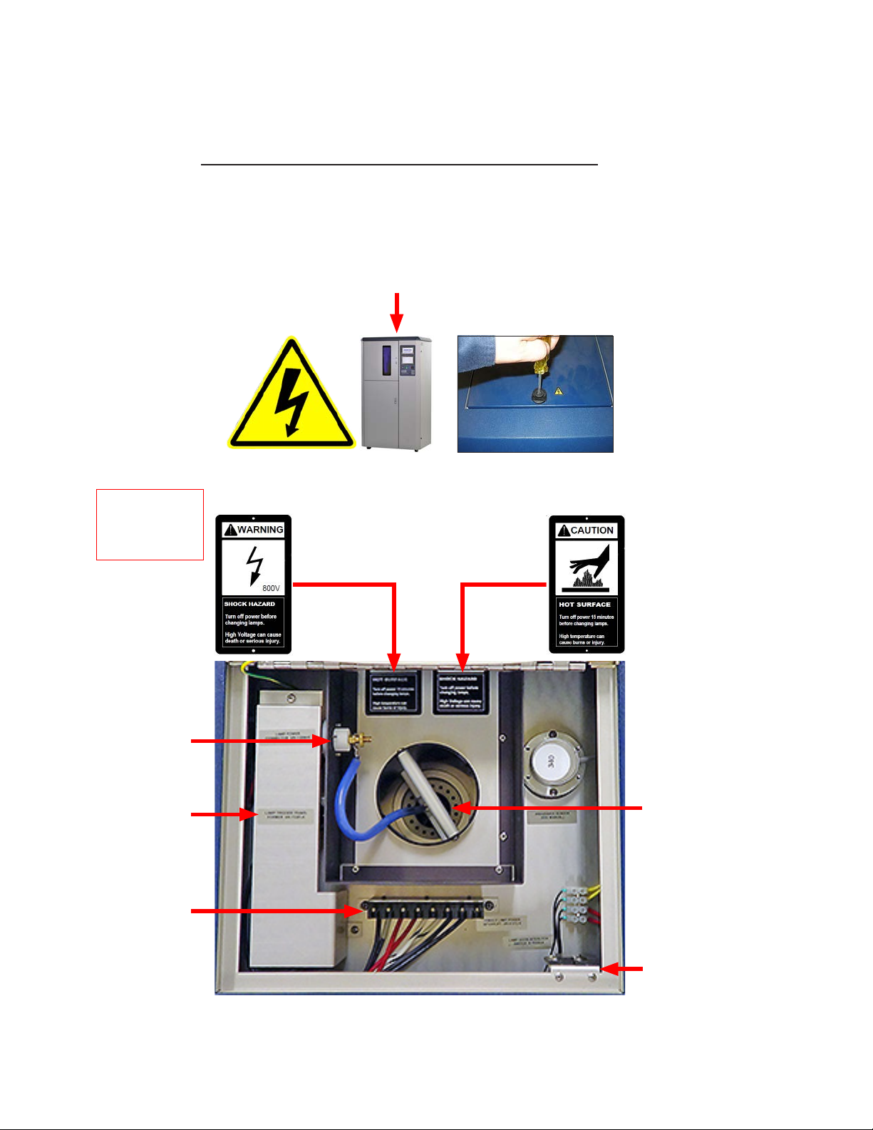
●Warning labels indicate heat and electric shock hazards inside the Q-SUN tester (Figure 2.1a and Figure 2.1b).
Figure 2.1a: Tester access door locations. Figure 2.1b: Hot surface and shock hazard warning labels.
Lower
Front Door
Left Side
Access Door
Right Side
Access Door
Test Chamber
Door
Lamp Door

Inside the Lamp Door
●IMPORTANT: Always shut off the Xe-2 power switch before opening the lamp door.
●The Xe-2 high-voltage xenon lamp is located under the lamp door on top of the machine.
●For safety, a tool (slotted screw driver) must be used to open the door (Figure 2.1c).
●Figure 2.1d shows safety labeling and electrical components.
●An interlock switch (Figure 2.1d) turns off lamp power when the lamp door is opened.
●The xenon lamp is very hot. Wait 15 minutes after stopping the machine to remove the lamp.
Section 2. Safety Information
6
Figure 2.1c: Lamp door located on top of the Xe-2 cabinet.
Figure 2.1d: Inside the lamp door.
800 Volt Wire
Lamp Power
Connector
High Voltage
Ignition
Transformer
(Under Cover)
Xenon
Lamp
Below
Interlock
Switch
WARNING
High voltage can
cause death or
serious injury.

Section 2. Safety Information
Inside the Chamber Door
●Items located in the test chamber, including specimens and holders, can be very hot.
●Let the test chamber cool before opening the chamber door.
Figure 2.1e: Opening chamber door. Figure 2.1f: Test chamber interior showing specimen
holders on turntable.
Inside the Side Doors
●For safety, a tool (slotted screw driver) must be used to open these doors.
●Electrical and heat generating components and safety labels are located throughout.
Figure 2.1g: Inside Left Door Figure 2.1h: Inside Right Door
Specimen
Holders
Turntable
7

8
2.2 Ultraviolet and Infrared Hazards (Nov 2020)
Chamber Door
●The Xe-2 xenon lamp can cause severe sunburn, eye inammation, and damage to your vision.
●Touch the stop icon on the Status Screen (Figure 2.2a) before opening the chamber door (see Section 12.2 for more
information on the Status Screen).
●An interlock switch (Figure 2.2b) shuts off power to the lamp when the test chamber door is opened.
Status Screen
Figure 2.2a: Stop icon on the Status Screen.
Interlock
Switch
Figure 2.2b: Test chamber door opened to show interlock switch location.
Section 2. Safety Information

●This Quick Set Up Guide is not a Technical Manual.
●This document is intended to explain only the basics of uncrating and setting up a Q-SUN Xenon Test Chamber.
●LX-5085-TM Q-SUN Xe-2 Technical Manual is necessary for a complete understanding of how to operate the
Q-SUN Xe-2 Xenon Test Chamber.
Overview
●The Q-SUN Xe-2 is equipped with an air-cooled xenon arc lamp to test the lightfastness of textiles as well as many
other materials.
●The Xe-2 is designed to meet ISO 105-B02, ISO 105-B04, AATCC Test Method 16, and many other test methods.
●All Xe-2 testers have a rotating specimen rack and provide precise control of critical test parameters including
irradiance level, black panel temperature, chamber air temperature, and relative humidity.
●The Xe-2 can be congured using one of a number of different optical lter types.
●Front water spray (Xe-2-HSE) and front water spray with back spray (Xe-2-HBSE) options are available.
●All Q-SUN Xe-2 models are “E” models that feature enhanced performance, including dual touchscreen control and
longer lamp life or higher irradiance capability.
Q-SUN Xe-2 Models Description
●This document covers the Q-SUN Xe-2 models shown here:
Model Conguration
Xe-2-HE H: Humidity Control
Xe-2-HSE S: Front Spray
Xe-2-HBSE BS: Back Spray (in addition to Front Spray)
Disposal
●When disposing of the Q-SUN Xe-2, please follow your local regulations.
●This equipment must be properly disposed of at end-of-life by means of an authorized waste management system.
9
3. General Description (Apr 2022)
Section 3. General Description

10
4. Operating Environment
The Tester Must Be Located in a Suitable Environment
●All Q-Lab test chambers are sophisticated scientic instruments.
●All tester models must be operated in a suitable controlled environment (Section 4.1).
●Operating the tester in an unsuitable environment (Section 4.2) will void the warranty.
4.1 Suitable Environments (May 2020)
Ambient Laboratory Temperature and Humidity
●The recommended ambient operating temperature and relative humidity (RH) for Q-SUN testers is 23 ± 5 °C and
50 ± 25% RH.
●Operating outside the recommended range (or in rare cases, even within it), certain standards or test cycle conditions
may not be achievable.
●Operating outside the recommended range can result in the tester producing chamber temperature and/or humidity
faults.
●Never operate your tester in lab temperatures >40 °C or >80% RH.
●Consult with Q-Lab for more specic information about achievable chamber temperature/humidity values based upon
various ambient lab conditions.
Physical Environment
●A room that is dry, clean, and free of dust, particles, gases, or salt fog.
●A room with an HVAC (heating/ventilation/air-conditioning) system.
●A location away from windows or HVAC vents.
●A location that provides the necessary minimum clearances as specied in Section 6.1.
Section 4. Operating Environment

11
4.2 Unsuitable Environments (Mar 2019)
Salt Fog or Other Airborne Contamination
●Operating the tester in an unsuitable environment will void the warranty.
●Do Not install Q-SUN testers in a room with Q-FOG or any other corrosion chambers (Figure 4.2a).
●Do Not locate Q-SUN testers in a room with machines or processes that generate dust, particles, vapors,
gases, etc (Figure 4.2b)
X
Figure 4.2a: Do Not Install Xe-2 Testers in a Room
with Corrosion Chambers
Figure 4.2b: Do Not Locate Tester in Room
with Airborne Dust, Particles or Gases
Uncontrolled Temperature and Humidity
●Do not operate the tester in a room with uncontrolled temperature and humidity (Figure 4.2b).
●Do not locate tester near sources of cold or hot air (Figure 4.2d).
X
Figure 4.2c: Do Not Locate Testers Near Open Windows
X
Section 4. Operating Environment

For further detail on laboratory environment requirements, please contact
Q-Lab Repair and Tester Support. See Section 9 for contact information.
X
HVAC Vent
Directly Above
Tester
Figure 4.2d: Keep Tester Away from Sources of Hot or Cold Air
Other Unsuitable Environments
●Outdoors: Rain and dust will corrode or short out electrical components.
●Metal Dust / Metal Chips: Do not locate the tester near metal cutting machines or metal grinding machines.
Conductive metal dust or metal chips in the air will damage electronic components.
●Carbon Fibers: Do not operate the tester where carbon bers or carbon reinforced plastic are being cut. The
conductive carbon bers will damage electronic components.
●Conductive Pigments: Do not operate the tester where carbon black or other conductive pigment dust is in the air.
The conductive dust will damage electronic components.
●Other Corrosive Gases: Do not expose the tester to acid fog, SO2gas, or other corrosive gases.
●Excessive Voltage: The electrical supply to the tester must be no more than 10% higher than the voltage listed on the
nameplate.
●Low Voltage: Recurring “brown-outs” or voltages less than 90% of the rated voltage will damage electrical
components.
●Water Leaks from Ceiling: Water leaking onto the tester will damage electrical components.
Section 4. Operating Environment
12

Page 13
Section 5. Uncrating
5. Uncrating (Mar 2022)
●Q-SUN Xe-2 testers are shipped in one of two types of crates (Figure 5a and Figure 5b).
●Labels on the crate indicate the location of the instructions to be opened rst (Figure 5c).
●Instructions for uncrating and setting up the tester are located in the envelope shown in Figure 5d.
Carefully read these instructions before uncrating the tester.
Follow all local, OSHA, EHS, and other applicable equipment handling
safety requirements, recommendations, and practices.
Figure 5a: This Crate has a Carton Banded to a
Wooden Skid.
Figure 5b: This Crate has a Wooden Frame
Surrounding the Carton.
Figure 5c: Labels on the crate indicate the envelope to
be opened rst.
Figure 5d: Open this envelope for important uncrating
instructions.
Open First Open First

1. Uncrating instructions are located in this envelope.
Remove and read the instructions.
Go To Step 3.
Crate with
Carton and
Wooden
Frame
Go To Step 6.
Crate with
Carton Only
2. For crate with wooden frame continue with Step 3.
For crate with carton only, go to Step 7.
3. Locate the six (6) Phillips screws in the bottom front
and back horizontal boards.
Remove
X3
Remove
X3
4. Remove all six (6) screws.
Three (3)
Screws in Front
Three (3)
Screws in Back
Weights
Crate with Carton Only Crate with Carton and Wooden Frame
Shipping Weight (Approximate): 182 kg (402 lb) 227 kg (500 lb)
Machine Weight: 172 kg (379 lb) 172 kg (379 lb)
Tools Required
Medium Phillips Screwdriver (Crate with Wooden Frame Only) Flat Blade Screwdriver
Pry Bar
(Crate with Wooden Frame Only) Ratchet and 15 mm (9/16”) Socket Small Ladder or Step Stool
Band Cutter Utility Knife Fork Lift*
*A fork lift or other mechanical lifting device is recommended for use in moving the crated tester to the
installation location, and to lift the frame in one piece from the crate with wooden frame.
14
Section 5. Uncrating

Section 5. Uncrating
15
5. If a fork lift is available, use it to carefully lift the
wooden frame up and off of the tester.
Use Fork Lift to
Remove Crate
in One Piece
6. If a fork lift is not available, use a pry bar to carefully
remove the horizontal and vertical wooden pieces
off of the tester.
Or Use Pry
Bar to Remove
Crate in Pieces
7. Cut the bands holding the carton to the skid.
Remove the bands.
Cut
8. Carefully lift the carton up and off of the tester.
9. Remove all plastic wrap, four (4) cardboard corner
posts, and foam blocks.
Remove Remove
10. Remove all bubble wrap from around the tester.
Remove Remove
Remove

16
11. Locate two (2) latches on the left side door and two
(2) latches on the right side door of the tester.
12. Open two (2) latches on the left side door and two
(2) latches on the right side door of the tester.
Open X2
Both Sides
13. Open the left side door and the right side door of
the tester.
14. Locate the two (2) nuts and bolts holding the tester
to the skid on the bottom left side.
Xe-2 Left Side Door Open
15. Remove the two (2) nuts and bolts holding the
tester to the skid on the left side.
Remove X2
16. Locate the two (2) nuts and bolts holding the tester
to the skid on the bottom right side.
Xe-2 Right Side Door Open
Section 5. Uncrating

IMPORTANT: The casters must be removed if an
optional Q-SUN lift kit is installed.
Optional Lift Kit
1 7. Remove the two (2) nuts and bolts holding the
tester to the skid on the right side.
Remove X2
18. At least two people are needed to move the Xe-2.
Carefully tilt the tester and remove the three foam
strips under the tester.
19. The Xe-2 is equipped with casters. Carefully roll the
tester off the skid. 20. Make sure the tester is installed on a level oor.
Install on
Level Floor
2 1. Remove any adhesive tape and accessory boxes
from the inside and outside of the tester.
Remove Foam
Strips X3
Tilt
Tester
Section 5. Uncrating
IMPORTANT: The casters must be removed if an
optional Q-SUN lift kit is installed
Optional Lift Kit

18
6. Setup
6.1 Dimensions and Space Requirements (Mar 2022)
●The Q-SUN Xe-2 uses room air for cooling.
●The tester does not require its own vent hood or ducting. Do not attach to a powered vent.
●The Q-SUN Xe-2 exhausts about 1800 W (6141 BTU/hr) of heat into the room.
●Allow adequate space around the tester for air ow and to access tester components (Figure 6.1).
Figure 6.1: Floor space required.
Section 6. Set Up
Drawing Not to Scale

19
Section 6. Set Up
6.2 Electrical (Jun 2022)
Specications
Voltage
All Models
230 V or 208 V ± 10% - single phase
Current 23 A @ 230 V, 24 A @ 208 V
Frequency 50 or 60 Hz
Installation Rated as Installation (Over voltage) Category II for transient over voltages.
SCCR* 1000 A
* Short Circuit Current Rating
Figure 6.2a: Electrical Specications
Voltage
●The Q-SUN Xe-2 comes in 208 V single phase or 230 V single phase (Figure 6.2a).
●The voltage is specied when the tester is ordered.
●The input voltage and current rating are shown on the nameplate at the rear of the tester (Figure 6.2b).
●The voltage supplied to the tester must be within ±10% of the voltage rating of the tester and the circuit must be
capable of supplying the rated current.
Connections
A power plug IS NOT SUPPLIED with Q-SUN Xe-2 testers. The user must supply
and attach a properly-sized plug to connect the Xe-2 to the Main Power Supply.
●Q-SUN Xe-2 testers are provided with a 3 conductor, 10 AWG, ≈ 4.5 m (15') long power cord without plug.
●A qualied electrician should make all electrical connections.
Q-SUN Xe-2
Rear View
Nameplate
Power
Cord
(Plug Not
Supplied)
Q-SUN XE-2-HS
22-1832-79-X2HS
Figure 6.2b: Tester voltage and current shown on nameplate.

20
6.3 Water (Mar 2022)
Overview
●Puried water must be supplied to all Q-SUN Xe-2 testers.
●Water is used by the humidier to produce humidity.
●Water is also used to spray on the test specimens in Xe-2 models with water spray.
●Q-SUN models with water spray require much higher water purity than those with a humidier and no water spray.
●Reverse osmosis / deionized (RO/DI) water is required.
●The Q-SUN tester warranty is voided if water purity conditions are not met.
Specications
System
(Model) Inlet Pressure Flow Setting Resistivity Conductivity Silica
Total
Dissolved
Solids
pH
Front Spray
(Xe-2-HSE) 30-80 psi
(207-522 kPa)
0.5L/min > 5 M Ω•cm < 0.2 μS/cm < 0.1 ppm < 0.1 ppm 6-8
Front and Back Spray
(Xe-2-HBSE) 5 psi > 5 M Ω•cm < 0.2 μS/cm < 0.1 ppm < 0.1 ppm 6-8
Humidier
(Xe-2-HE)
3-80 psi
(21-552 kpa) 1.0 L/hr > 200 k Ω•cm < 5.0 μS/cm Not
Important < 2.5 ppm 6-8
NOTE: Average Daily Volume is dependent on individual test cycles. See Section 11.
Figure 6.3a: Q-SUN Xe-2 water purity requirements.
Reverse Osmosis / Deionization System
The reverse osmosis / deionized (RO/DI) water system described on the next page produces water pure enough for
spray systems. This type of RO/DI system is required for water spray in Xe-2 testers.
Use Type I, not Type II anion in the mixed bed tanks of the DI system.
The Strong Base Type I Anion resin in the mixed bed tanks is the most important part of these systems to prevent water
spotting. This is because strong base Type I anion resin is the only resin that can effectively remove suspended silica.
Suspended silica is the major cause of specimen spotting. Type I anion is much better at removing suspended silica
than Type II. Unfortunately, Type II is the most common anion. So be sure to insist that your water purication supplier
installs Type I, not Type II. The cost for Type I anion is about the same as Type II.
Type I anion is only necessary in the mixed bed “polishing” stages of the deionization (Figure 6.3b, Stage E), not in the
initial “rough” purication stages.
Flush out the water supply line prior to connecting to the Xe-2 tester.
Section 6. Set Up
This manual suits for next models
1
Table of contents
Other Q-Lab Test Equipment manuals
Popular Test Equipment manuals by other brands

Tru-Test
Tru-Test XRS Stick Reader quick start guide

Hanna Instruments
Hanna Instruments HI 38040 instruction manual

CHERNE
CHERNE HI-FLOW AIR-LOC LINE ACCEPTANCE instructions

sauter
sauter TVL operating instructions

AEMC
AEMC SR751 user manual

System Sensor
System Sensor RTS151 Installation and maintenance instructions