vi
Read the following safety information.
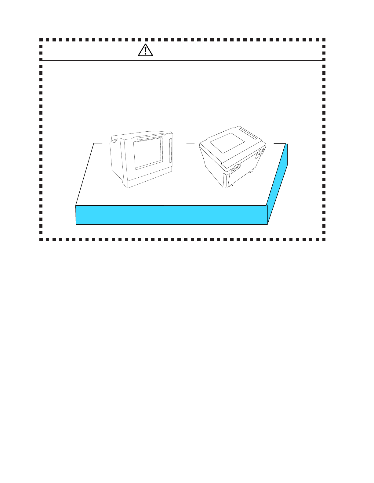
Installation
• Always use this instrument only within the rated operating range. If used over
the rated range, failure may occur.
Use this instrument only indoors.
Operating conditions
Temperature: 0 to +40°C
Humidity: 80% RH or less (non-condensing)
Height: 2,000 meters or less
• Do not block the air ventilation holes or exhaust fan of this instrument. Blocking
the airflow could result in excessive internal heating and fire or electric shock.
• Leave a space behind and to the sides of the instrument.
Be careful to avoid overheating of the instrument when installing the instrument
in a rack mount or on another measurement machine. Failing to observe this
precaution may result in faulty operation or performance.
• Do not place this instrument in a location with excessive moisture or dust,
otherwise fire or electric shock could result.
Power Supply
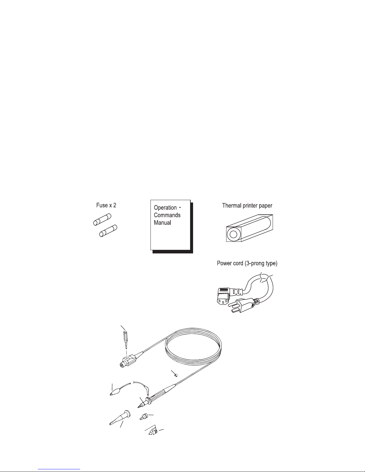
• Use only the specified fuse (φ5 ×20 mm, 250 V, T3.15 A) when replacing the
fuse. Failure to replace the fuse with the correct rating could result in fire, electric
shock or damage to the unit.
To replace the fuse:
a) Turn the power switch to STBY before disconnecting the power cord.
b) Disconnect the power cord before replacing the fuse.
When measuring
• Do not apply a voltage exceeding the specified value to the input terminals (CH1,
CH2, CH3, CH4). This may cause malfunction. The following is a maximum
voltage that can be input.
Direct
1 MΩ: ±400 V (DC+ACpeak≤5 k Hz)
When SS-0130R (10:1) equivalent probe is used: ±600 V (DC+ACpeak)
[Note]: Maximum voltage that can be input may decrease depending on the
frequency or high voltage pulse of the input signal.
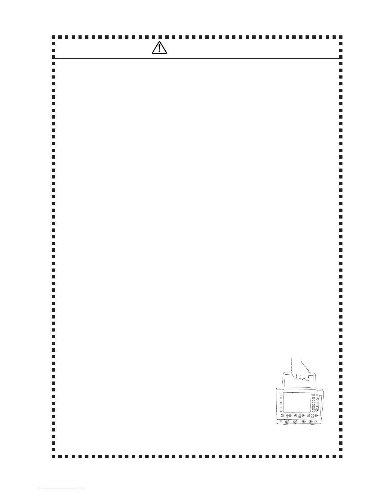
• When a probe or measurement cable is connected, be careful so that you do not
pull the probe or measurement cable causing the instrument to overturn.
Letting the instrument overturn may cause electric shock, injury, fire or
malfunction.
Cautions