Q-Pumps QIM Series Setup guide

2
Assembly and installation manual
QIM/QDB Mixer Series
QIM/QDB-M01
CONTENTS
About this Manual . . . . . . . . . . . . . . . . . . . . . . . . . . . . . . . . . . . . . . . . . . . . . . . . . . . . . . . . 3
Q-Pumps Warranty . . . . . . . . . . . . . . . . . . . . . . . . . . . . . . . . . . . . . . . . . . . . . . . . . . . . 3
Safety . . . . . . . . . . . . . . . . . . . . . . . . . . . . . . . . . . . . . . . . . . . . . . . . . . . . . . . . . . . . . . . . . . 4
important safety information . . . . . . . . . . . . . . . . . . . . . . . . . . . . . . . . . . . . . . . . . . . . . . 4
Installation . . . . . . . . . . . . . . . . . . . . . . . . . . . . . . . . . . . . . . . . . . . . . . . . . . . . . . . . . . . . . . 5
Instalation guidelines . . . . . . . . . . . . . . . . . . . . . . . . . . . . . . . . . . . . . . . . . . . . . . . . . . . 5
How to install the piping . . . . . . . . . . . . . . . . . . . . . . . . . . . . . . . . . . . . . . . . . . . . . . . . . 6
Assembly preliminaries . . . . . . . . . . . . . . . . . . . . . . . . . . . . . . . . . . . . . . . . . . . . . . . . . 7
Exploded Assembly . . . . . . . . . . . . . . . . . . . . . . . . . . . . . . . . . . . . . . . . . . . . . . . . . . . . . . . 8
Part List . . . . . . . . . . . . . . . . . . . . . . . . . . . . . . . . . . . . . . . . . . . . . . . . . . . . . . . . . . . . . . . . 9
Assembly . . . . . . . . . . . . . . . . . . . . . . . . . . . . . . . . . . . . . . . . . . . . . . . . . . . . . . . . . . . . . . . 10
Beggining the assembly . . . . . . . . . . . . . . . . . . . . . . . . . . . . . . . . . . . . . . . . . . . . . . . . 10
Leg bracket assembly . . . . . . . . . . . . . . . . . . . . . . . . . . . . . . . . . . . . . . . . . . . . . . . . . . 10
Adapter assembly . . . . . . . . . . . . . . . . . . . . . . . . . . . . . . . . . . . . . . . . . . . . . . . . . . . . . 11
Spacing of the impeller and stub shaft . . . . . . . . . . . . . . . . . . . . . . . . . . . . . . . . . . . . . . 12
Assembling and installing the mechanical seal . . . . . . . . . . . . . . . . . . . . . . . . . . . . . . . . 15
Assembling the casing . . . . . . . . . . . . . . . . . . . . . . . . . . . . . . . . . . . . . . . . . . . . . . . . . 17
Assembling the QDB . . . . . . . . . . . . . . . . . . . . . . . . . . . . . . . . . . . . . . . . . . . . . . . . . . . 19
Common Problems . . . . . . . . . . . . . . . . . . . . . . . . . . . . . . . . . . . . . . . . . . . . . . . . . . . . . . . 23
Thank you for purchasing a Q-Pumps product!
This manual contains installation and maintenance instructions for the QIM/QDB Mixer Series
It also includes a part list as well as a troubleshooting chart to assist in determining pump mal-
function and practical advices for the maintenance and operation of the equipment.

3
Assembly and installation manual
QIM/QDB Mixer Series
QIM/QDB-M01
ABOUT THIS MANUAL
To ensure the best performance of your pump, please read this manual before starting it. You will
nd useful information and instructions for the assembly and disassembly procedures required for the
necessary pump maintenance.
For any questions related to the operation, maintenance or installation, please contact your local
distributor or directly to Q-Pumps:
Q-Pumps S.A. de C.V.
Acceso “A” #103, Fracc. Industrial Jurica
Querétaro, Qro., México, 76130
Call: +52 (442) 218 4570 y +52 (442) 103 3100
Fax: +52 (442) 218 4577
E-mail: support@qpumps.com
Web: www.qpumps.com
The information in this manual might change without notice, we recommend to visit our website for any
updates.
Q-Pumps S.A. de C.V. Warranty
Q-Pumps guarantees that all manufactured and sold products are free from defects in materials and
manufacture for a period of one (1) year from the date of shipment. The warranty does not apply to products
which require repair or replacement due to what is considered normal wear. Conditions caused by normal
wear include (but are not limited to standard rotors wear) casing, mechanical seals, gears and bearings wear.
Accidents, operating errors or improper maintenance are not covered by the warranty. Q-Pumps
assumes no liability for incidental, accidental or consequential damages. The purchaser by acceptance
of delivery assumes all liability for the consequences of use or misuse by it, its employees or third parties.
Unless they are approved in advance, Q-Pumps does not assume any costs related to parts and / or
service.
Q-Pumps disclaims any responsibility for modications or conversions to the pump and the system. For
security reasons and functionality use original parts only. The use of other parts voids the warranty and
excludes liability for any consequences.
The pump is designed only for pumping uids under established characteristics in the selection sheet. Any
other use besides the intended one without the prior written consent of the manufacturer’s application,
will result in disclaim of any responsibility from Q-Pumps.
If the pump is stored temporarily or indenitely, avoid weather exposure and protect the connection
ports with plastic plugs supplied with your pump. Turn the pump shaft by hand every two months to
change the rotating position of the bearings.
ABOUT THIS MANUAL

4
Assembly and installation manual
QIM/QDB Mixer Series
QIM/QDB-M01
IMPORTANT SAFETY INFORMATION
Safety is very important!
DO NOT attempt to modify any Q-Pumps product, the QIM/QDB Mixer Series have been
designed to be safe and reliable, to do so could create unsafe conditions and void all warranties.
DO NOT place any Q-Pumps product in an application where general product service
ratings are exceeded. If the maintenance and operation personnel do not observe the
instructions in this manual could result in personal injury or machine damage.
The following DANGER, WARNING, and CAUTION signs and their meanings are used within
these instructions to avoid serious injury and/or possible damage to equipment.
CODE 136530002
(Guard warning)
Safety labels are placed on every pump. DO NOT remove any labeling on any Q-Pumps pro-
duct. Replace any label that is missing.
WARNING
ROTATING SHAFT
DO NOT OPERATE
WITHOUT GUARD IN PLACE
Indicates an imminently hazardous situation
which, if not avoided, will result in death or
serious injury. The word danger is used in the
most extreme cases.
DANGER
Indicates a potentially hazardous situation
which, if not avoided, could result in minor
or moderate injury. May also be used to alert
against an unsafe operating or maintenance
practice.
WARNING
Indicates a potentially hazardous situation
which, if not avoided, could result in death or
serious injury.
CAUTION
CODE 136530001
(Rotating direction ccw)
SAFETY

5
Assembly and installation manual
QIM/QDB Mixer Series
QIM/QDB-M01
Before servicing pump, disconnect
electrical power source, carefully relieve
all pressure and drain all fluids from
pump and connected piping.
DESCRIPTION
Before servicing pump, disconnect electrical power source.
The QIM/QDB Mixer Series closed-coupled pumps are made up of two sections, power or drive
section and the liquid end or pump section.
The pump is mounted to the frame of the drive motor by means of an adapter, and is coupled
to the motor shaft. The impeller mounts on the stub shaft and is retained by one of the three
methods. The casing is clamped to the adapter, greatly simplifying removal, and also permitting
positioning of the discharge outlet through 360º. The external, balanced seal assures long seal
life. The drive motor is mounted on a frame having adjustable legs providing simple installation
and leveling.
INSTALLATION GUIDELINES
UNPACKING EQUIPMENT
Check the contents and all wrapping when unpacking your equipment. Inspect all parts for
damage that may have occurred during shipping. Report any damage to the carrier.
LOCATION AND INSTALLATION
The pump unit should be located as near as possible to the liquid source and in a position where
the suction piping can be short and direct with a minimum number of elbows and ttings. It
should also be readily accessible for inspection and cleaning.
The pump unit as received from the factory is ready for installation. To install it, attach a hoist if
necessary, loosen the set screws in the adjusting leg brackets, and individually adjust the legs
until the pump is leveled. Tighten the set screws.
Attach the suction and discharge piping. Be sure suction and
discharge piping is properly supported to avoid any strain on the
pump casing.
WARNING
SAFETY

6
Assembly and installation manual
QIM/QDB Mixer Series
QIM/QDB-M01
HOW TO INSTALL THE PIPING
GENERAL
This section provides some do’s and do not’s of piping which will aid in obtaining the maximum
eciency and service from your pump. Piping should be independently supported at both the
suction inlet and discharge outlet. Care should be taken that piping is properly aligned and does
not put any strain on the pump casing. The piping should have as few bends as possible.
SUCTION PIPING
The suction piping should be short and follow a direct route with a minimum number of elbows
and ttings. Elbows should be located as far as possible from the suction inlet to prevent head
loss due to increased friction. Excessive friction losses in the suction line could result in pump
cavitation, causing poor performance, noise, vibration, damage to equipment and possible
damage to uid.
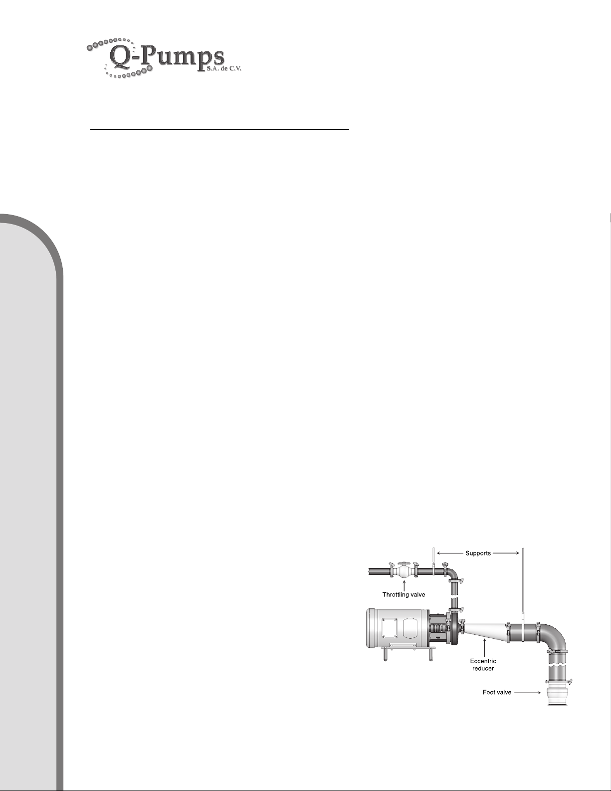
Whenever possible the diameter of the piping at the suction inlet should be increased in size, an
eccentric tapered reducer should be used instead of a concentric tapered reducer to prevent
air pockets from forming and impairing pump eciency. In turn, the eccentric reducer may be
placed at the inlet of the pump and should be positioned so the straight side is up. A horizontal
suction pipe must have a gradual rise to the pump. A high point in the suction line will form an
air pocket and prevent proper pump operation. All joints in the suction line should be air tight, to
prevent air leakage which can reduce pump capacity and eciency.
DISCHARGE PIPING
Position of the pump discharge is preferably either vertical or top horizontal. The discharge piping
should be short and direct with a minimum number of elbows and ttings. Elbows should not be
used at the discharge outlet, as the friction encountered would be increased, resulting in head
loss. However, use of a large discharge pipe than recommended may reduce the total pump
head, but increase the pump volume, which can cause pump vibration due to overload. Use
of a discharge pipe smaller than the pump discharge outlet increases the total pump head but
decreases the volume. If a reducer is required on the outlet port of the pump and the discharge
is vertical a concentric reducer should be used. If the
discharge is horizontal an ec centric reducer should be
used and should be positioned so the straight side is
down.
LOCATING VALVES
In suction lift applications where the lift is not very
high, it may be desirable to install a foot valve, to
facilitate priming, and to prevent draining o of the
liquid back to the source. A throttling valve should
be installed in the discharge piping to provide control
pump ow rate and prevent motor overload.
INSTALLATION

7
Assembly and installation manual
QIM/QDB Mixer Series
QIM/QDB-M01
ASSEMBLY PRELIMINARIES
Before beginning the assembly procedure identify every element that is going to be installed,
you can use the exploded view and part list shown in pages 8 and 9. During the assembly you
may need the following tools:
1. 1”, 3/4”, 9/16” and 1/2” Wrenches.
2. 3/16” and 1/4” Allen wrenches.
3. Rubber mallet.
4. Caliper or shims.
5. 5/8” & 7/8” Socket – for impeller nut.
6. 3/8” diameter steel rod – to hold stub shaft plus.
7. Torque Wrench
WARNING
Before servicing pump, disconnect electrical
power source, carefully relieve all pressure and
drain all uids from pump and connected piping.
INSTALLATION

8
Assembly and installation manual
QIM/QDB Mixer Series
QIM/QDB-M01
EXPLODED ASSEMBLY
1
90A
2S
6P
11F
24C
24D
71
71A
71B
71C
75
91B
92
92A
96
131
133
209
207
209A
209B
M
11A
96H
96F
96C
96G
96E
96A
71C
71
71B
96D
96B

9
Assembly and installation manual
QIM/QDB Mixer Series
QIM/QDB-M01
PART LIST
ITEM DESCRIPTION QTY
1Casing 1
2S Impeller 1
6P Stub shaft 1
11A Back plate 1
11F Backplate pin 2
11J Backplate cup (only models
4410/6410)
2*
11K Flat head screw (only models
4410/6410)
2*
24C Impeller key 1
24D Impeller nut 1
71 Adaptader 1
71A Long pin (except models
4410/6410)
2*
71B Hexagonal screw 4
71C Hexagonal nut (only IEC B5 fra-
mes)
4
75 Clamp assembly (except model
4410/6410)
1
76 Clamp assembly (only models
4410/6410)
1
76A Hexagonal brass nut (only mo-
dels 4410/6410)
2
76B Washer (only models 4410/6410) 2
76C Hexagonal screw (only models
4410/6410)
2
76D Clamp assembly bracket 2
90A Casing O-ring 1
91B Impeller front gasket 1
92 Stub shaft collar 1
PART LIST
ITEM DESCRIPTION QTY
92A Allen screw **
96 Internal mechanical seal 1
96A Rotary holder 1
96B Rotary single seal face 1
96C Static single seal fase 1
96D Single seal spring 1
96E Rotary holder O-ring 1
96F Static single seal O-ring 1
96G Rotary single seal O-ring 1
96H Seal pin 1
96I Rotary double seal face 1
96J Double seal spring 1
96K Rotary double seal O-ring 1
96L Double seal rotary holder 1
96M Set screw 2
96N Static double seal fase 1
131 Guard 1
133 Hexagonal screw 1
207 Leg 4
209 Bracket 2
209A Hexagonal screw 4
209B Hexagonal screw 4
* Not used in some models.
** May be needed 1 or 2 pieces depending on model.

10
Assembly and installation manual
QIM/QDB Mixer Series
QIM/QDB-M01
START THE ASSEMBLY
It is highly recommended that you use the general diagram to identify
the components and thus be able to carry out the assemblies and sub-
assemblies that will be explained below.
1. LEG BRACKET ASSEMBLIES
The leg bracket assemblies are optional. They allow to level the pumps adjusting the legs
vertically. The size of the brackets (209) and legs (207) depend on the NEMA or IEC motor
frame.
First make the sub-assemblies of the legs to the brackets with the hexagonal screws (209A).
Next, with the hexagonal screws (209B) x the brackets to the motor base; You may need
to lift the motor to make this assembly. Figure A.
Figure A.
ASSEMBLY

11
Assembly and installation manual
QIM/QDB Mixer Series
QIM/QDB-M01
For NEMA motors “C” face and IEC motors “C DIN” face (B14 ange) and “C” face (FC
ange) use the four hexagonal screws (71B). Figure B.
For IEC motors “FF” face (B5 ange) use also the hexagonal nuts (71C). Figure C.
2. ASSEMBLY THE ADAPTER TO THE MOTOR
Place the stainless adapter (71) on the motor ange and x it with hexagonal screws and
tighten to the torque values recommended in Chart 1.
Figure B.
Figure C.
ASSEMBLY
Chart 1 – Torque values for tightening the adapter screws
Torque ft-lb Models NEMA Models IEC
20 Frame 56 to 14 Frame 80 to 90
55 Frame 18 to 25 Frame 110 to 160
70 Frame 28 Frame 180
110 Frame 32 to 36 Frame 200 to 225

12
Assembly and installation manual
QIM/QDB Mixer Series
QIM/QDB-M01
3. SPACING OF THE IMPELLER AND STUB SHAFT
The correct functioning of the pump depends on the separation of the impeller (2S) from
the backplate (11A) and the xation of the stub shaft (6P) on the motor shaft. Follow the
next steps to x the stub shaft on the motor shaft:
3a. Position the stub shaft collar (92) with the corresponding Allen screws (92A) loosely
on the stub shaft and place it on the motor shaft, it must slide in and out without problem.
Figure D.
3b. Place and x the backplate into the adapter. Two long pins are used in the adapter
(71A) normally preassembled; if there are no pins please insert them into the holes drilled
in the adapter ring. Those pins help to x the backplate into the adapter using two bended
backplate pins (11F). The bended pins shall be clockwise seeing them from the back side
of the backplate.
Seat the backplate on the adapter and turn it counterclockwise until the bended pins
engage with the long pins. If the bended pins get separated or they do not mate with the
long pins, try to adjust them by turning in or out. Figure E.
The bended pins help to keep the backplate in position to make the assembly easier.
Figure D.
Figure E.
ASSEMBLY

13
Assembly and installation manual
QIM/QDB Mixer Series
QIM/QDB-M01
3c. Put the impeller key (24C) on the keyway of the stub shaft. Place only the rotary holder
of the mechanical seal (96A) together with its respective O-ring (96E) until it seats on the
shoulder of the stub shaft. The impeller key does not interfere with the mechanical seal
drive collar.
Take the impeller nut (24D) and place the impeller gasket (91B) on it, then place the impeller
in the stub shaft and tighten with the impeller nut compressing the assembly. Figure F.
Use a 5/8” hexagonal socket for models 114 and 214 and a 7/8” hexagonal socket for the
rest of models to tighten the nut.
To prevent the stub shaft-impeller assembly from turning you can use a Ø3/8” rod in the
bore that has the stub shaft on its side and thus be able to tighten or loosen the impeller
nut. Figure G.
Remember that you can use water or dishes soap to lubricate or glue O-rings and
gaskets to the metal elements to facilitate assembly.
Fig ure F.
Figure G.
ASSEMBLY

14
Assembly and installation manual
QIM/QDB Mixer Series
QIM/QDB-M01
3d. Once the assembly is tightened place a spacer of 0.060” (1.53 mm) thru 0.070” (1.78
mm) between the back of the impeller and the front of the backplate. You may use a
caliper, some shims or a washer with that width to set the critical distance for the correct
performance of the mechanical seal. Keep aligned both, the stub shaft slot and the collar
slot before tightening the screws on the shaft collar. Compress the impeller against the
backplate with the spacer between them and proceed to tight the screw or screws on the
shaft collar. Now turn the impeller by hand, it must turn with no restriction. Check that
every blade is separated the distance indicated. Figure H.
Use the torque values for tightening the collar screws indicated in the Chart 2.
f
L
Figure H.
Chart 2.
Align stub shaft
and collar slots
0.060” (1.53 mm)
0.070” (1.78 mm)
Chart 2 – Torque values for tightening the stub shaft collar Allen screws
Torque ft-lb Models NEMA Models IEC
15 Frame 56 to 18 Frame 80 to 112
30 Frame 21 to 25 Frame 132 to 160
40 Frame 28 to 32 Frame 180 to 225
ASSEMBLY

15
Assembly and installation manual
QIM/QDB Mixer Series
QIM/QDB-M01
3e. Using the 3/8” rod and the hexagonal socket and wrench to untighten the impeller
nut to remove the elements previously assembled. Take the impeller nut, impeller gasket,
impeller and impeller key o. Do not forget to remove also the spacer used to determinate
the stub shaft position. Continue assembling the mechanical seal (96). Figure I.
4. ASSEMBLING THE SINGLE MECHANICAL SEAL
4a. Place into the backplate the stationary face of the mechanical seal (96C) with its O-ring
(96F). First place the O-ring on the stationary face, remember that you can use water or
dishes soap to lubricate or glue O-rings and gaskets to the metal elements to facilitate
assembly, place both pieces in the inner housing of the backplate taking care that the
notch in the stationary face coincides with the backplate pin (96H). Push until the seal
surface fully seats on the surface of the housing. Figure J.
Figure I.
Figure J.
ASSEMBLY

16
Assembly and installation manual
QIM/QDB Mixer Series
QIM/QDB-M01
Place and x the backplate with the stationary seal into the adapter, as in step 3b.
4b. Assembly the rotary single seal face (96B), the rotary seal O-ring (96G), spring (96D)
and rotary holder O-ring (96E) into the rotary holder (96A). Remember that you can use
water or dishes soap to lubricate or glue O-rings and gaskets to the metal elements to
facilitate assembly.
First place the O-ring in the groove on the rotary holder. Then place the spring inside the
rotary holder taking care the tip on the spring ts the machined slot in the rotary holder.
Put the rotary seal face into the rotary holder. The tip on the spring must t the machined
slot in the rotary seal face. Then compress until the rotary seal face is inserted. Finally
place the rotary holder O-ring in the groove on the front of the holder. Figure K.
4c. Insert the whole rotary seal assembly into the stub shaft, the seal will contact the
stationary seal face placed previously in the backplate. Push to compress the assembly
and then insert the impeller key. Put the impeller and tight it with the impeller nut. Do not
forget to place the impeller gasket into the impeller nut. Figure L.
Figure K.
Figure L.
ASSEMBLY

17
Assembly and installation manual
QIM/QDB Mixer Series
QIM/QDB-M01
Tight the assembly as previously did before in step 3c. For models 114 and 214 use a
torque of 25 ft.lb and a torque of 40 ft.lb for the rest of the models when tightening the
impeller nut. Figure M.
5. ASSEMBLING THE CASING
5a. Once the mechanical seal has been installed and the impeller-impeller nut assembly
has been tightened the casing must be mounted.
Place the casing O-ring (90A) onto the groove on the front of the backplate. Then take the
casing (1) and locate it onto the adapter, positioning the discharge at the desired location.
Place the clamp assembly (75) around the casing. Figure N.
In a lower horizontal position, the casing can be self-drainable.
Figure M.
ASSEMBLY
Vertical position
Horizontal position Lower horizontal position
45º Inclination

18
Assembly and installation manual
QIM/QDB Mixer Series
QIM/QDB-M01
5b. Tighten the clamp assembly to close the casing to the adapter, be sure it is centered
and level around all the circumference. Avoid that the casing ts unevenly in the adapter to
prevent it from rubbing against the impeller. A rubber mallet may be helpful when installing
the casing hitting softly to even the separation while tightening the clamp assembly. Figure
O.
5c. Check turning by hand the impeller it does not rubs against the casing. The assembly
may turn easily without restriction. If there is any sound or sensation of rubbing, you need
to check the whole assembly, disassembly and repeat it again.
5d. If everything is ne, to complete the assembly place the protective guard (131) that is
xed with a hexagonal screw (131A) into the adapter.
It is highly recommended for safety reasons not to operate the equipment if it is not placed
in the adapter.
Notes.
Before starting the pump check that the motor turns in a counterclockwise direction.
Keep the suction line ooded and the mechanical seal lubricated with the uid which
is going to be pumped. Never operate the pump when dry or it may damage the seal.
Maintain enough NPSH available in the suction line to avoid the pump to cavitate.
Do not support the weight of the pipe on the pump casing, the pipe must be adequately
supported to avoid this.
The impeller for QIM/QDB series must be trimmed to a specic diameter. If you
need to spare the impeller do not forget to tell it is for a QIM/QDB equipment.
Figure O.
ASSEMBLY

19
Assembly and installation manual
QIM/QDB Mixer Series
QIM/QDB-M01
6. ASSEMBLING THE QDB
6a. Identify the elements that conform the standard QDB assembly. Figure 1.
6b. Check that the QDB table (T) has installed the wheels (W) and is clear for assembling
the QIM (Q) on it. If the wheels are not installed, then install them. Assembly the QIM to
the motor (M). Follow the instructions described on sections 2 thru 5 to do this. Figure 2.
(C) – Clamp assemblies (x 3 pieces)
(G) – Clamp Gaskets (x 3 pieces)
(H) – Hopper
(M) – Motor
(Q) – QIM (In-Line Mixer)
(T) – Table
(T1) – Hexagonal screws (x 4 pieces)
(T2) – Hexagonal nuts (x 4 pieces)
(T3) – Hexagonal screws (x 2 pieces)
(T4) – Hexagonal nuts (x 2 pieces)
(V) – Ball valve
(W) – Wheels (x 4 pieces)
(Y) – Y-elbow
Figure 1.
Figure 2.
ASSEMBLY
M
Q
Y
V
H
C
G
W
T1
T3
T4
T
T2

20
Assembly and installation manual
QIM/QDB Mixer Series
QIM/QDB-M01
ASSEMBLY
6c. Place the QIM onto the QDB table and x the motor using the hexagonal screws (T1)
and nuts (T2) to the brackets on the table. Do not tight the screws until the hopper (H) is
installed. Figure 3.
6d. Install the Y-elbow (Y) in the suction of the QIM. Use the clamp gasket (G) and clamp
assembly (C) to x it. Keep the Y-elbow top suction horizontal aligned. Be sure the clamp
gasket is placed correctly to avoid leaking. Figure 4.
Figure 3.
Figure 4.
This manual suits for next models
3
Table of contents