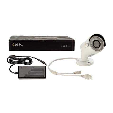
Q-See QC-SERIES User manual

H.264 NETWORK VIDEO RECORDERS
Variable D1 and HD Recording Options
User Manual
QC-SERIES IP CAMERAS

2 3
© 2011-2012 Q-See. Reproduction in whole or in part without written permission is
prohibited. All rights reserved. This manual and software and hardware described herein, in
whole or in part, may not be reproduced, translated, or reduced to any machine-readable
form without prior written approval.
Trademarks: All brand names and products are trademarks or registered trademarks of their
respective owners.
Q-See is a registered trademark of DPS, Inc.
Disclaimer: The information in this document is subject to change without notice. The
manufacturer makes no representations or warranties, either express or implied, of any kind
with respect to completeness of its contents.
Manufacturer shall not be liable for any damages whatsoever from misuse of this product.
Thank You for Choosing a Q-See Product!
All of our products are backed by a conditional service warranty covering all hardware for 12
months from the date of purchase. Additionally, our products also come with a free exchange
policy that covers all manufacturing defects for one month from the date of purchase.
Permanent upgrading service is provided for the software and is available at www.Q-See.com.
Be certain to make the most of your warranty by completing the registration form online. In
addition to warranty and technical support benefits, you’ll receive notifications of product
updates along with free downloadable firmware updates for your NVR. Register today at
www.Q-See.com!
Please see the back of this manual for exclusions.
This manual is written for the QCN7001B, QCN7002D, QCN8001B and QCN8002D IP
Cameras and was accurate at the time it was completed. However, because of our ongoing
effort to constantly improve our products, and the different capabilities of the three models
additional features and functions may have been added since that time and on-screen
displays may change. We encourage you to visit our website at www.Q-see.com to check for
the latest firmware updates and product announcements.
This manual covers the setup and local operation of the IP cameras whether used in
conjunction with an NVR or as stand-alone devices. Instructions for use with an NVR is written
specifically with Q-See’s QC-Series NVRs. If you are using another brand, please consult your
system’s manual for configuration instructions. The QC-Series User Manual and Remote
Monitoring Guide will both be useful in configuring your system. Both are included on the
CD that accompanied your NVR and can likewise be found on www.Q-See.com/support.
Throughout the manual we have highlighted warnings and other important information that will
assist you in operating your new system in a safe and trouble-free manner. Please take the
time to read and follow all instructions and pay attention to alerts as shown below:
About this Manual
NOTE! Text in blue boxes with the Information icon offer additional guidance
and explanations about how to make the most out of your system.
IMPORTANT! Red boxes with this icon indicate warnings. To prevent
possible injury or damage to the product, read all warnings before use.
Version 1.0 8/8/12

5
TABLE OF CONTENTS
1. CAMERA SPECIFICATIONS 8
QCN7001B 8
QCN7002D 9
QCN8001B 10
Adjusting the lens 11
QCN8002D 14
2. CONNECTING IP CAMERAS 16
2.1 What are IP Cameras? 16
2.2 Connecting an IP Camera 17
Locally connecting to an NVR 17
Cameras connected through a network 18
2.2 Adding and Removing Cameras in Your System 20
Local cameras 20
Cameras on the same network 20
QC NVR Remote Device menu 21
2.3 Connecting Your Camera to a Remote Network 24
Before you get started 24
Obtaining IP Information using IPCONFIG in Windows 25
Testing the connection 27
Opened ports and Internet IP address 29
2.4 Troubleshooting Network Connections 30
Opening ports 30
Issues with DHCP 34
Multiple routers on the nNetwork 35
Configuring ActiveX 38
2.5 Additional Network Services 43
Entering the DNS information into the camera 45
2.6 Dynamic Domain Name Service (DDNS) 47
3. USING WEB SERVICE 48
3.1 Live View 48
Function Buttons (PC only) 49
3.2 Setup 50
Camera 50
Video 51
3.3 Network 52
TCP/IP 52
Static IP Address 52
PPPoE 53
DDNS 53
IP Filter 53
SMTP (E-Mail) 54
UPnP (Universal Plug ‘n’ Play) 54
Bonjour 54
3.4 Event 55
Motion Detection 55
Video Masking 56
Disconnection 56
IP Conflict 56
3.5 Record 57
Record shedule 57
Snapshot schedule 57
File destination path 58
Record control 58
3.6 System 59
General 59
Date & time 59
Account 60
Default 60
Import/export 60
Auto maintain 60
Upgrade 60
Information 61
Alarm 62
Logout 62
4. PRO SURVEILLANCE SOFTWARE 63
4.1 Installing PSS 63
Installing PSS on a PC 63
Installing PSS on a Mac 64
4.2 Using Pro Surveillance Software (PSS) 65
Connecting to the camera 67
Real-time monitor 69
Image view options 70
Window controls 71
Tool bar 72
Function buttons 75
(Contents continued on next page)

6 7
5. MOBILE SURVEILLANCE 78
5.1 iPhone and iPad 78
5.2 Android 83
5.3 BlackBerry 87
5.4 Symbian 90
5.5 Windows Mobile 93
Q-SEE PRODUCT WARRANTY 95
Questions or Comments? Contact Us 95

8 9
CAMERA SPECIFICATIONS CHAPTER 1
QCN7001B
System
Main Processor Texas Instruments DaVinci high-performance DSP
OS LINUX
System Resources Supports simultaneous real-time network, local record, and
remote operation
User Interface Remote operation through Web Service and PSS
Image Sensor 1/3” 1.3 Megapixel Aptina CMOS
Lens 6mm
IR LEDs / Range 30 LED / 100’
Video
Pixel 1280 x 960
Day/Night Mode Electrical Day/Night
Signal/Noise Ratio >50dB
Min. Illumination 0.1LUX/F1.2 (color) 0.05LUX/F1.2 (b/w)
Gain Control Manual/Auto
White Balance Manual/Auto
Exposure Mode Manual/Auto NTSC: 1/3-1/10000
Comp. Standard H.264/JPEG/MJPG
Image Resolution 1.3M (1280x960), 720p (1280x720), D1 (704x480)
Encoding Speed NTSC: 1.3M @15fps + D1@15fps,
720p @30fps + D1@30fps
Video Bit Rate H.264 128Kbps-8192Kbps
Snapshot 1f/s snapshot. Files saved as JPG
Network
Ethernet RJ-45 (10/100Base-T)
Network Functions HTTP, TCP/IP, IPv4/IPv6, ARP, IGMP, ICMP, RTSP, RTP, UDP,
SMTP, FTP, DHCP, DNS, DDNS, PPPoE, UPNP, NTP, Bonjour,
SNMP, Onvif
Remote Operation Monitor, PTZ control, Playback, System setting, File
download, Log information, Maintenance & Upgrade
Operation
Power Supply DC12V, PoE
Consumption Max.1.5W
Operating
Environment 15°F to +120°F (-10°C to+50°C) Humidity 10%-90%
PICTURE 1-1
System
Main Processor Texas Instruments DaVinci high-performance DSP
OS LINUX
System Resources Supports simultaneous real-time network, local record, and
remote operation
User Interface Remote operation through Web Service and PSS
Image Sensor 1/3” 1.3 Megapixel Aptina CMOS
Lens 3.6mm
Video
Pixel 1280 x 960
Day/Night Mode Electrical Day/Night
Signal/Noise Ratio >50dB
Min. Illumination 0.1LUX/F1.2 (color) 0.05LUX/F1.2 (b/w)
Gain Control Manual/Auto
White Balance Manual/Auto
Exposure Mode Manual/Auto NTSC: 1/3-1/10000
Comp. Standard H.264/JPEG/MJPG
Image Resolution 1.3M (1280x960), 720p (1280x720), D1 (704x480)
Encoding Speed NTSC: 1.3M @15fps + D1@15fps,
720p @30fps + D1@30fps
Video Bit Rate H.264 128Kbps-8192Kbps
Snapshot 1f/s snapshot. Files saved as JPG
Network
Ethernet RJ-45 (10/100Base-T)
Network Functions HTTP, TCP/IP, IPv4/IPv6, ARP, IGMP, ICMP, RTSP, RTP, UDP,
SMTP, FTP, DHCP, DNS, DDNS, PPPoE, UPNP, NTP, Bonjour,
SNMP, Onvif
Remote Operation Monitor, PTZ control, Playback, System setting, File
download, Log information, Maintenance & Upgrade
Operation
Power Supply DC12V, PoE
Consumption Max.1.5W
Operating
Environment
15°F to +120°F (-10°C to+50°C) Humidity 10%-90%
QCN7002D
PICTURE 1-2
10 11
In addition to its video surveillance functions, the QCN8001B is able to accept input from
other devices and either pass their signals back to an NVR, or utilize them to trigger recording
or alert actions when it is being used in a stand-alone role. The camera has 32GB of internal
memory allowing it to record video and still images without the need for an NVR.
By using the audio input and output to connect both a microphone and speaker - and with
similar audio equipment on the user’s end, two-way communication can take place. Two
alarm sensors can be connected to the alarm block with a single output to an audible alarm,
an external alarm input or to a DVR. When used with an NVR or on a network, the alarm signal
can trigger recording and its signal can be transmitted via the Cat 5 cable to an NVR.
1
2
34
5
67
8
# Item Function
1 Storage Internal 32GB memory
2 Reset Resets camera if user is locked out.
3 Audio In Input for optional microphone
4 Audio Out Connect to speaker
5 RJ45 (Ethernet) Port For network connectivity, video output and power input (via
POE)
6 Alarm 2 Alarm inputs 1 Output
7 Power For use without POE
8 Video Out BNC video output (for testing
QCN8001B
PICTURE 1-3
ADJUSTING THE LENS
The QCN8001B has a lens that can be manually adjusted between 3.3mm and 12mm.
The 3.3mm setting provides a 67° field of view. The 12mm setting enlarges subjects by
approximately three times compared to the 3.3mm configuration, with the field of view
narrowing to 22°.
The camera is set at the factory to the 3.3mm
position. To adjust the lens, you will have to
first remove the black cover at the front of the
camera by twisting it counter-clockwise. Take
care not to damage the cover or the threads
during this step.
Once the cover has been removed, you can
adjust the zoom and focus using the two
knobs located on the lens body behind the
LED circuit board. You may need to loosen
them by twisting the knob counter-clockwise
before making the adjustments. Do not apply
excessive force to the knobs as they can
snap off, leaving your camera unable to be
adjusted.
PICTURE 1-4
PICTURE 1-5
It is recommended that you have some way to view the camera’s view while making the
adjustments to ensure that the image is properly in focus and includes the entire area that
you wish to monitor. This can be done using a camera tester connected to the BNC Video
Out plug or by connecting it to an NVR where you can monitor it using the video display. A
third method would be by connecting the camera to a network using the steps described in
Chapter 2 and then accessing it remotely using a mobile device with a sufficiently large screen
clarity. However, with this method it is important to keep in mind that mobile devices use the
lower-quality substream video so final adjustments may still need to be made.

12 13
System
Main Processor Texas Instruments DaVinci high-performance DSP
OS LINUX
System Resources Supports simultaneous real-time network, local record, and
remote operation
User Interface Remote operation through Web Service and PSS
System Status SD card status, bit stream stats, log, and software version.
Image Sensor 1/3” 2.0 Mp SONY progressive scan Exmor CMOS
IR LEDs 18
Max IR range 65’
Min. Illumination 0.1LUX/F1.6 (color), 0.01LUX/F1.6 (b/w), 0LUX (w/IR)
Lens Auto-Iris 3.3-12mm@F1-6
Video
Pixel 1920x1080 (1080p)
Day/Night Mode Automatic
Auto Aperture DC drive
Gain Control Fixed/Auto
White Balance Manual/Auto
Exposure Mode Manual/Auto NTSC: 1/4-1/10000
Video Comp.
Standard
H.264/JPEG/MJPG
Video Frame Rate NTSC: Main stream 1080P @30fps, 1.3M @30fps, 720P
@30fps; Substream 704x480@30fps
Video Bit Rate H.264 56Kbps-8192Kbps
MJPG is adjustable along with bit rate
Video Flip Supported
Snapshot 1f/s snapshot. Files saved as JPG
Privacy Mask Maximum 4 privacy zones supported
Video Adjustment Brightness, contrast, hue, saturation and gain
Video Info Channel title, time, motion detection, masking
Motion Detect 396 (18x22) zones. Six sensitivity levels. Motion detection
activation options: alarm, recording, snapshot, log and e-mail
Audio
Audio Ouput 1-channel RCA
Bidirectional Talk Reuses first audio input channel
Audio Bit Rate 128/64/10.2 Kbps
Audio Comp. G.711a/G.711u/PCM
Network
Network 1-channel wire Ethernet port, 10/100 Base-T Ethernet
Network Protocols Standard HTTP, TCP/IP, ARP, IGMP, ICMP, RTSP, RTP,UDP,
RTCP, SMTP, FTP, DHCP, DNS, DDNS, PPPOE, UPNP, NTP,
Bonjour,SNMP.
Remote Operation Monitor, PTZ control, system setup, file download, log
information, maintenance and upgrade.
Recording
& Backup
Recording Priority Manual>External alarm >Video detect>Schedule
Local Storage 32GB internal
Backup Remote through PSS
Auxilliary
Connectors
Video Output 1-channel BNC analog video out
Audio Input 1-channel RCA
Audio Output 1-channel RCA
Alarm 2-channel input, 1-channel output
Power
Power Through RJ45 connector when connected to POE or 12v .5A
through aux. power connector
Consumption <10W
Env.
Temperature 15F to 140F
IP Rating IP66
Humidity 10-90%
QCN8001B Specifications

14 15
System
Main Processor Texas Instruments DaVinci high-performance DSP
OS LINUX
System Resources Supports simultaneous real-time network, local record, and
remote operation
User Interface Remote operation through Web Service and PSS
System Status SD card status, bit stream stats, log, and software version.
Image Sensor 1/3” 2.0 Mp SONY progressive scan Exmor CMOS
Min. Illumination 0.1LUX/F1.6 (color), 0.01LUX/F1.6 (b/w), 0LUX (w/IR)
Lens Auto-Iris 3.6@F1-6
Video
Pixel 1920x1080 (1080p)
Day/Night Mode Automatic
Auto Aperture DC drive
Gain Control Fixed/Auto
White Balance Manual/Auto
Exposure Mode Manual/Auto NTSC: 1/4-1/10000
Video Comp.
Standard
H.264/JPEG/MJPG
Video Frame Rate NTSC: Main stream 1080P @30fps, 1.3M @30fps, 720P
@30fps; Substream 704x480@30fps
Video Bit Rate H.264 56Kbps-8192Kbps
MJPG is adjustable along with bit rate
Video Flip Supported
Snapshot 1f/s snapshot. Files saved as JPG
Privacy Mask Maximum 4 privacy zones supported
Video Adjustment Brightness, contrast, hue, saturation and gain
Video Info Channel title, time, motion detection, masking
Motion Detect 396 (18x22) zones. Six sensitivity levels. Motion detection
activation options: alarm, recording, snapshot, log and e-mail
Audio
Audio Ouput 1-channel RCA
Bidirectional Talk Reuses first audio input channel
Audio Bit Rate 128/64/10.2 Kbps
Audio Comp. G.711a/G.711u/PCM
Network
Network 1-channel wire Ethernet port, 10/100 Base-T Ethernet
Network Protocols Standard HTTP, TCP/IP, ARP, IGMP, ICMP, RTSP, RTP,UDP,
RTCP, SMTP, FTP, DHCP, DNS, DDNS, PPPOE, UPNP, NTP,
Bonjour,SNMP.
Remote Operation Monitor, PTZ control, system setup, file download, log
information, maintenance and upgrade.
Recording
& Backup
Recording Priority Manual>External alarm >Video detect>Schedule
Local Storage 32GB internal
Backup Remote through PSS
Auxilliary
Connectors
Video Output 1-channel BNC analog video out
Audio Input 1-channel RCA
Audio Output 1-channel RCA
Alarm 2-channel input, 1-channel output
Power
Power Through RJ45 connector when connected to POE or 12v .5A
through aux. power connector
Consumption <10W
Env.
Temperature 15F to 140F
IP Rating IP66
Humidity 10-90%
QCN8002D
PICTURE 1-6

16 17
2.1 WHAT ARE IP CAMERAS?
Internet Protocol (IP) or Network cameras differ from conventional video cameras in that each
is a stand-alone device with a built-in processor of its own. Rather than being processed and
encoded on the recorder, the video is instead processed and encoded on the camera itself
before being sent to the recorder. The onboard processor allows the camera to operate on its
own with the video being available directly from the camera itself. The video can be recorded
onto internal memory (depending on model), sent to an FTP drive, accessed by a computer
or be streamed directly to a Digital Network Video Recorder (NVR) using standard network
protocols.
When it is connected to the NVR - whether locally, through a network or over the Internet the
NVR treats an IP camera as a peripheral device with the NVR serving as the control interface
and recording system.
Q-See’s QC-series NVRs feature an industry-exclusive built-in Power Over Ethernet (POE)
block that allows you to connect up to four IP cameras directly to it up to 200 feet away using
RJ-45 (Ethernet) cables without the need to purchase a separate power block or to locate
the cameras near power outlets. The Ethernet cable will both power the camera and deliver
the video signal to your system. Cameras beyond the number of POE ports, or those located
away from the NVR will require a separate power source, such as from the powered port of a
POE hub, or from a power supply. This power source must be located between the camera
and the network. It is not possible to power a camera through a network or over the Internet
using a POE port.
Cameras connecting to your system over a network (local or Internet) will also ultimately
connect through your network’s router and their signal will be received by the NVR through its
Network port. Cameras located outside of the network, and those being used as stand-alone
devices, will be accessed by using their web address - whether by entering it into the NVR, a
web browser, or through a surveillance program.
CONNECTING IP CAMERAS CHAPTER 2 2.2 CONNECTING AN IP CAMERA
LOCALLY CONNECTING TO AN NVR
Your IP camera delivers video through a standard Cat 5, 5A or 6 Ethernet cable connected
to the RJ-45 socket at the end of the cable leading from the camera. Under most conditions,
power is delivered to the camera through this cable when it is connected to a POE block.
Regardless of how it is connected to the NVR, it is best to use a continuous length of cable,
whenever possible, rather than multiple short segments as each intervening connection could
result in a small loss of power and signal.
The following directions are for connecting your IP camera(s) to one of Q-See’s QC-Series
NVRs with a built-in POE block of powered Ethernet ports. If you are using another brand of
NVR, please consult that system’s user manual.
STEP 1. Connect one of the long
Ethernet cables to the socket on the
wire leading from the camera.
STEP 2. Plug the other end of the
Ethernet cable into any of the Power
over Ethernet (PoE) ports on the back
of the NVR or into a stand-alone POE
block.
In the latter cases, the camera will
also need to be connected to a
network.
STEP 3. Repeat for additional cameras.
PICTURE 2-1
PICTURE 2-2

18 19
Using the Power Over Ethernet Block
Your NVR’s POE block will power up to four cameras while receiving their video signals. This
is the primary and preferred method to connect cameras to your NVR. This feature cannot be
expanded through use of a network switch. These ports are also not to be used to connect
the NVR to a network router. When an IP camera is connected to the NVR through the POE
port, it will receive power immediately, but there may be a delay of up to a minute before the
camera’s signal appears on the screen as the system establishes connectivity.
If you are unsure, and if your camera has
infrared LEDs, you may cup your hand over
the lens area to activate the infrared night
vision mode. You will see a faint red glow
from the LEDs confirming that the camera
has power.
NVR
POE
Block
POE
Block
NVR
POE
Block
POE
Block
Network
Network
Port
POE
Router NVR
POE
Block
POE
Block POE
Router/
Modem
POE
Router/
Modem
NetworkNetwork
Port
Internet
Internet
PICTURE 2-3
NVR
POE
Block
POE
Block
NVR
POE
Block
POE
Block
Network
Network
Port
POE
Router
NVR
POE
Block
POE
Block POE
Router/
Modem
POE
Router/
Modem
NetworkNetwork
Port
Internet
Internet
Alternately, if your NVR was bundled with cameras, they may include a power input as
additional power option. You will need to acquire a power adapter that matches the ratings
listed on the camera itself if you are not connecting them to a POE.
The NVR will connect to these cameras through the same cable that it uses to communicate
with the network.
PICTURE 2-4
CAMERAS CONNECTED THROUGH A NETWORK
There are two types of networks – local (LAN or Intranet) and Internet (or WAN). Cameras can
be accessed by the NVR over both types.
Local Networks
For cameras positioned too far away to
reasonably run a network cable directly to the
NVR, you can connect it to the same network
as the NVR and the system will be able to
access and use them.
Ultimately, each camera will have to connect
to the same router that the NVR is connected
to. They will need to be connected to a
power source on their side of the network -
preferably a POE - as the POE block on the
NVR itself is unable to provide power through
the network.
NVR
POE
Block
POE
Block
NVR
POE
Block
POE
Block
Network
Network
Port
POE
Router
NVR
POE
Block
POE
Block POE
Router/
Modem
POE
Router/
Modem
NetworkNetwork
Port
Internet
Internet
Connections Over the Internet
A third connection option is via the Internet.
This method is more complicated, but it
allows the user to view cameras that are
located in a completely different building –
or region – from the NVR itself. In essence,
your NVR will be remotely monitoring those
cameras. As such, the user will need to
forward ports using the IP Tool software
included on the Manuals and Software
CD to obtain the IP address for any camera
that will be accessed over the Internet. Full
instructions are covered in Chapter 2.
PICTURE 2-5

20 21
PICTURE 2-6
PICTURE 2-7
REMOTE DEVICE
Filter None
IP Search Manual Add
Add Cancel
2 IP Address Port Device ID Manufacturer Type
1 10.1.1.65 1 YZC2OC061966 Private IPC-HFW210
2 10.1.1.67 2 YZCAU192012 Private IPC-HFW321
2.2 ADDING AND REMOVING CAMERAS IN YOUR SYSTEM
LOCAL CAMERAS
Once you have connected your cameras, you will need to add them to your system’s
display. For cameras connecting to one of Q-See’s QC-Series NVRs, they will automatically
appear on-screen shortly after being plugged in. Cameras will be assigned to the first
available channel by the NVR in this case, regardless of which port in the block that they
were connected to. These cameras can only be removed from your display by physically
disconnecting the cameras from the NVR.
CAMERAS ON THE SAME NETWORK
Cameras sharing the network with the NVR will not automatically connect. There are three
ways to connect them on a QC-Series NVR. The first two methods are by either using the
Add Camera icon in the Live View window, or right-clicking within it. The third method uses
the Remote Device window located in the Main Menu.
Add Camera
Moving the cursor to the center of any empty
channel will reveal the Add Camera icon
shown in Picture 2-6. Clicking on this will
open a window listing available cameras.
Clicking on IP Search will refresh this list.
Simply click on the desired camera from the
list and it will become the camera for that
channel. Please note that it is possible to load
a camera which is already in use by another
channel. In which case, you will have two
identical channels.
PICTURE 2-8
PICTURE 2-9
QC NVR REMOTE DEVICE MENU
Use of remote IP cameras connected to a network - whether local or remote - requires
your NVR to be connected to a router. It also requires that the cameras are connected to a
router as well - even if it isn’t the same one as the NVR. If you intend to connect to devices
that are located outside of your local network, then this router must be able to access the
Internet. Instructions for connecting your system to the Internet are presented in the Remote
Monitoring Guide that also came on the CD with your system. It is also available from our
online resource at www.Q-See.com/Support.
Similarly, the remote devices must be able to communicate with the local network or Internet.
This will be covered in Section 2.3. You will need to follow the instructions in that chapter in
order to obtain an IP address for any cameras that will be accessed over the Internet. Once
you have connected your cameras to a router you can connect to them using the Remote
Device window.
This window can be reached by clicking on
the Remote Device icon in the Main menu...
MAIN MENU
SEARCH INFO SETTING
ADVANCED BACKUPREMOTE DEVICE
SHUTDOWN
...or through the Shortcut menu by right-
clicking on the screen and selecting Remote
Device.
View 1
View 4
View 8
View 9
View 16
Pan/Tilt/Zoom
Color Setting
Search
Record
Remote Device
Alarm Output
Main Menu

22 23
PICTURE 2-10
REMOTE DEVICE
Filter None
Delete Manual Add
IP Search Add
OK Cancel
4 IP Address Port Device ID Manufacturer Type
1 10.1.1.65 Port 1 YZC2OC061966 Private IPC
2 10.1.1.67 Port 2 YZCAU192012 Private IPC
3 10.1.1.68 Port 4 TC2FW25600095 Private IPC
4 196.219.8.50 4000 Private
channel Edit Delete Status IP Address Port Device ID
1 196.610.6.46 37777
2 10.1.1.67 Port 2 YZCAU192012
3 10.1.1.68 Port 4 TC2FW25600095
4 10.1.1.65 Port 1 YZC2OC061966
Device Added
When the window opens, you will be presented with a list of all conneced devices in the
lower portion. This section, marked Device Added, indicates the status of each device along
with other information about it.
Icon Meaning Description
Editable You may edit the settings on this device by double-clicking on it
Cannot
Delete
This device is connected directly to the NVR and must be physically
unplugged to be removed from this list.
Removable This device may be deleted from the list by checking the box next to
it and clicking on the Delete button below.
Device
Status OK
The connected device is operating normally.
Device
Error
There is an issue with the connected device that is preventing it from operating
normally.
Clicking on IP Search under the upper portion of the window will generate a list of all devices
that the NVR was able to locate - both directly connected as well as connected to the same
network as your system. Items showing a short IP address beginning with “10” are cameras
directly connected to the NVR and who’s IP addresses were assigned by the NVR itself. Care
should be taken that you do not attempt to connect a device that is already connected to the
system as it will create a duplicate video feed and could cause connectivity issues.
Edit
Double-clicking on a device in the Device Added portion of the window will display
information regarding the connected remote device. Making any changes within this window
will not change anything on the camera or remote device itself. To make those changes, you
will need to access the camera or other remote device (such as a DVR) directly, or through
one of the remote methods described in the Remote Monitoring Guide.
Once you have made those changes, you will need to update the user name and password
within the Edit window. Failing to change these in this window will result in an on-screen
message about incorrect password and may lock you out of the IP camera for a period of 30
minutes in the case of QC-Series cameras - other brands may vary.
It is important that you do not remove the
device you are making the changes upon
from the list of connected devices before
editing the information in the Edit window. If
you later remove the device from the list and
wish to reconnect, you will need to do so
using the Manual Add feature as described
below.
Similarly, if you already know the IP address
and port of the camera, you can use the
Manual Add feature.
PICTURE 2-11
REMOTE DEVICE
Filter None
Delete Manual Add
IP Search Add
OK Cancel
4 IP Address Port Device ID Manufacturer Type
1 10.1.1.65 Port 1 YZC2OC061966 Private IPC
2 10.1.1.67 Port 2 YZCAU192012 Private IPC
3 10.1.1.68 Port 4 TC2FW25600095 Private IPC
4 196.219.8.50 4000 Private
channel Edit Delete Status IP Address Port Device ID
1 196.610.6.46 37777
2 10.1.1.67 Port 2 YZCAU192012
3 10.1.1.68 Port 4 TC2FW25600095
4 10.1.1.65 Port 1 YZC2OC061966
Device Added
EDIT
Channel
Manufacturer
IP Address
TCP Port
User
Password
Remote Channel
Decoder Buffer
1
Private
IPC.myq-see.com
32555
admin
1
280
Save Cancel
IMPORTANT! To avoid connection issues, you should not change the
information within the Edit window unless you have first made those changes
to the remote device itself.
The lower portion of the window shows all devices currently connected to your NVR. If all of
your channels are occupied, you will need to delete one of the connected devices from this
list by selecting the check box next to it and clicking delete. Items with a gray “X” are directly
connected to your NVR and may only be removed by physically disconnecting them from your
system.
Clicking on the IP Search button will create a list of all remote devices that the NVR was able
to detect. You may limit this search to only IP cameras by selecting IPC in the Filter pull-
down. Items being accessed by your NVR over the Internet will not appear in the list at the top
of the window. They must be added manually (see below).
If you have an available channel, you may add a device by selecting the check box next to it
and then clicking Add. Please note that if you changed the default user name and password
for your camera(s) in the Web Service application as described in Chapter 3, you will need to
use the the Manual Add feature instead.

24 25
2.3 CONNECTING YOUR CAMERA TO A REMOTE NETWORK
As was mentioned in the previous section, cameras connected to the same network router
as the NVR can be discovered by that system and added. Cameras on a different network
require additional steps to be connected to an NVR, and these same steps are needed if one
is going to be accessing the camera only using a computer or mobile device.
First and foremost, you will need to physically connect your camera to a router. This router can
be part of an existing network of computers, or it can be the router/modem supplied by your
Internet Service Provider (ISP) to connect you to the Internet. This connection will be made by
plugging the other end of the Ethernet cable that you connected to the camera into a router or
into an Ethernet port that connects to a router.
You cannot connect the camera to the Internet through a modem because there is no method
available to cause the modem to dial out to the ISP. Your camera will need to be directly
connected to its own power supply - whether it is a power adapter or a Power Over Ethernet
(POE) block. In the case of the latter, the POE block will then connect to the router or network.
Your camera is not designed to be connected wirelessly to a network. It is also recommended
that the router that the camera is connected to should be connected directly to the Internet
rather than to another router if Internet access is desired as multiple routers can create
problems with connectivity. You will also need to have a computer connected to the same
router - at least temporarily - to make certain settings. If, after following the instructions you
are still not able to access your NVR, please see Section 2.4 Troubleshooting Network
Connections later in this chapter.
In order to access your camera over the Internet, you will have to determine its IP address.
Each device on a network - both a LAN or the Internet - has a specific IP address. This
address is what allows different devices on the network to communicate with each other. You
will also need to confirm that two ports, or openings, have been permitted by your router to
allow communication to and from your camera.
BEFORE YOU GET STARTED
You will need to have:
• Your router’s brand, model number and manual. The manual is also usually available on
your router’s manufacturer’s website.
• The “Manuals and Software” CD that came with your camera. It contains necessary
software and links to other important programs which are mentioned in this guide.
• Your router’s password (the default password should be in your router’s manual).
• Your router’s Gateway address.
If your camera is able to automatically connect to your network, you will only need your
router’s Gateway address to connect to your camera from outside of the local network.
However, if your camera is unable to connect automatically, you will need this information in
order to make the connection.
OBTAINING IP INFORMATION USING IPCONFIG IN WINDOWS
You will need to get your router settings to not only create an IP address, but for the Default
Gateway information as well.
To get the router settings:
STEP 1. To access the router’s settings you will need to enter the Command (CMD)
panel on a computer also connected to the same router.
STEP 2. Type “ipconfig” at the prompt
(Red arrow in Picture 2-14) to
access router settings.
STEP 3. Write down the Default Gateway
number (bottom green arrow).
A. WINDOWS XP – Select Run from
your Windows START menu (lower
left of screen) and type “cmd” after
the prompt.
Microso Office Outlook 2007
Microso Internet Explorer
All Programs
Devices and Printers
Default Programs
Help and Support
iTunes
Adobe Acrobat
Inbox Microsof... iTunes
start
start
Shut Down
Log Off
Run
B. WINDOWS VISTA and WINDOWS
7 – Click on the START menu
(Windows icon) in the lower left of
your screen. Type “cmd” into the field
that says, “Search programs and
files” and hit ENTER or click on the
magnifying glass icon.
PICTURE 2-12
PICTURE 2-13
PICTURE 2-14
Microso Office Outlook 2007
Scky Notes
All Programs
Devices and Printers
Default Programs
Help and Support
Shut down
iTunes
Adobe Acrobat
cmd

26 27
PICTURE 2-15
PICTURE 2-16
PICTURE 2-17
OBTAINING IP INFORMATION USING A MAC
The easiest method for locating the router’s Gateway address for Macintosh is through the
computer’s Network window.
STEP 1. Click on the System
Preferences icon at the bottom of
the Macintosh’s screen.
STEP 2. Click on the Network icon.
STEP 3. Make sure that your network
connection is highlighted in the list of
connections to the right of the main
part of the Network window and
that its status reads “Connected.”
The Router’s IP address will be
displayed.
PICTURE 2-18
PICTURE 2-19
When ConfigTool launches, it will produce
a list of all QC-Series IP cameras that are
connected to the same network. This
will confirm that your camera has been
successfully added to your network.
To ensure that the camera and the
connection are operating properly, right click
on the camera’s name in the list.
A pop up window saying, “Open Device
Web” will open. Click on it to open a browser
window.
When the browser window has opened, you
will be presented with a login screen for the
Q-See Web Service. Since you’re on the
same network as the camera, you will want to
select LAN from the options at the bottom of
the screen.
PICTURE 2-20
PICTURE 2-21
To test this, once you have connected the
IP camera to a network, you will need to run
the ConfigTool software on a computer
connected to the same router.
This Windows software is located in the
Software folder on the CD that came with
your system. Macintosh computer users will
need to use the Search Device function
within the Device Manage window in PSS
to locate the camera. PSS is covered in
Chapter 4.
PSSPSS
TESTING THE CONNECTION
Your camera features UPnP (Universal Plug ‘n Play) connectivity. This allows network devices
to be automatically added to the network and communicate with other devices within it
without additional setup. If your Network router has this feature - and it is turned on - your
camera may be accessible from the moment you connect it to the network.

28 29
PICTURE 2-22
The default username and password are admin and admin. It is recommended for security
reasons that you change the password before you add the device to your NVR. See Section
3.6 for instructions on modifying the password on your camera.
Internet Explorer users may be asked to download an ActiveX plug-in from Q-See
International, Ltd. Firefox and Chrome users may be asked to allow QuickTime to run. In these
cases, you should allow the required plugins to operate. In some cases, you will be returned
to the log in screen after the plugin has loaded. This is normal.
Although ConfigTool is Windows only, the Web Service browser program will operate on
Macintosh computers as well. To access your camera without ConfigTool, simply enter the
camera’s local IP address into the browser window on a computer located on the same
network.
After you log in, you should see live video
from your camera. This confirms that your
connection and camera are operating
optimally. You may also use the Web Service
program to access your camera separately
from your NVR. The camera can also be
accessed through the PSS software included
on the CD. These are both covered in the
next chapters.
Once you have confirmed that you can access your camera on a local network - and if you
wish to access it from over the Internet - you will need to confirm that the camera’s ports have
been opened as well as obtain the camera’s Internet IP address
If you are unable to see video from your camera, you should check all connections and ensure
that your computer software is operating properly. You may also wish to try to connect using
a different browser or computer if the problem persists. Instructions for opening ports and
troubleshooting connection issues are provided in the next section.
PICTURE 2-23
Browser - Windows Internet Explorer
Fine 100%
Open Port Check Tool
Page Safety Tools
hp://canyouseeme.org/
Protected Mode: On
Your IP: 81.919.622.24
What Port?
CanYouSeeMe.org - Open Port Check Tool
Check
This page will serve as a free utility for remotely verifying a port is open or closed. It will
be useful for users who wish to check to see if a server or ISP is blocking certain ports.
Success: I can see your service on
81.919.622.24 on port (85)
Your ISP is not blocking port 85
OPENED PORTS AND INTERNET IP ADDRESS
Just as with your NVR, you will need to confirm that your ports are open and that your camera
is accessible from the Internet. You will also need to get the Internet IP address which you will
use to connect to the camera outside of its local network.
Confirming that the ports have been opened
To confirm that your ports have been forwarded successfully, go to www.canyouseeme.org
using a computer connected to the same router as the camera.
STEP 1. Enter “85” into the box labeled
“What Port?”
STEP 2. Click on the Check button.
STEP 3. You should see a green
“Success” message. If not, return to
ConfigTool and double-click on the
camera in the list. Change port 85 to
81 or 83 and click Apply to save your
changes before checking using that
new number on CanYouSeeMe.
STEP 4. Repeat for port 37777. If there
is a problem with port 37777, then try
37000 in the same manner as above.
Obtaining Internet IP address
This website will also display your Public IP address near the top of the page above the box
where you entered your port number. This is the first part of the number which you will use to
access the IP camera using your NVR, the PSS software, the Web Service browser app or
your mobile device from outside of your local network (away from the building in which your
NVR is located). The second part is the first port number that you confirmed was open. Using
the number shown in the image above, you would enter http://81.919.622.24:85 with 85
being the opened port. If you used a number other than 85 for the first port, you will use that
instead, placing it after the colon (“:”) in the address.
Be sure to record this address for use at your NVR. If you had to use a different port than
37777 you will need to record that as well.

30 31
2.4 TROUBLESHOOTING NETWORK CONNECTIONS
OPENING PORTS
The most common factor causing network connection issues is for communication between
the device and a device outside the network to be blocked. The router’s built-in-firewall is
designed to keep malicious users and software out of the network. At times, this can also
block legitimate connections. To avoid this, routers can allow communication to pass through
specific ports within the firewall. These “virtual tunnels” only allow access to specific devices
within the network. Properly managed with passwords and other safeguards, these do not
pose a threat to the security of the network.
If your network’s router has the UPnP feature turned on, it and the camera should “discover”
each other on the network in less than a minute. Ports 85 and 37777 will be “forwarded”
to the camera’s local network IP address, allowing it to communicate with the Internet. The
former allows you to control the camera, while the latter port is used by the camera for the
video stream.
However, some brands of routers, such as the 2Wire used by AT&T for it’s Uverse service
do not include this feature. In this case, the ports will need to be manually forwarded using
one of the methods described on the next few pages. You will only need to use one of these
methods - which are the same if you are using a Macintosh or Windows PC. If you are still
unable to connect your NVR to the Internet using any of these procedures, the likely cause
is the presence of multiple routers on your network. Solutions to overcome that situation are
presented at the end of this section.
Regardless of the method you use, you will need to get your router’s Public (Internet) IP and
Gateway addresses in order to log into the router, and eventually connect to the camera.
Option 1: UPnP
Check your router’s manual to confirm the presence of the UPnP feature. You may need to log
into your router to turn it on. There are legitimate reasons to disable UPnP, but you may wish
to enable it briefly in order to allow the camera to connect. Once you’ve confirmed that the
camera’s ports have been opened and you’ve set the camera to use a Static IP address as
described later in this section, you can disable UPnP.
The location of the UPnP settings within your router vary by brand and model. Consult your
router’s manual to locate and enable this feature before continuing.
Option 2: Opening Ports Using DMZ
The exact location of DMZ within the router’s settings vary by manufacturer so please consult
your router’s manual for the location of this feature. The method for accessing your router’s
settings, however, is pretty standard.
STEP 1. On a computer connected to
the same router as your camera,
open a web browser and enter the
Gateway (Router’s IP address) into
the browser window’s address bar to
access your router.
STEP 2. Locate the DMZ settings in
your router. Each manufacturer is
different so please consult your
router’s manual for the location of this
setting. Two examples are shown at
right.
STEP 3. Enable DMZ.
STEP 4. Enter the NVR’s IP address.
STEP 5. Click on Apply or Save to
preserve your settings.
Leave your router control panel open as you
will need to obtain DNS information from
your router in Section 1.5 Domain Name
System (DNS). You should now proceed to
the section entitled Confirming that Ports
are Opened.
PICTURE 2-25
PICTURE 2-26
PICTURE 2-24
Browser - Windows Internet Explorer
Fine 100%
Web Client Page Safety Tools
hp://10.6.196.6
Protected Mode: On
LIVE SEARCH BACKUP TOOLS INFOCONFIG
2011-10-06 18:16:49
Status
P.T.Z
Color
Master Stream
Sub-Stream
Local Recording Status
1 2 3 4 5 6 7 8
9 10 11 12 13 14 15 16
1 2 3 4 5 6 7 8
9 10 11 12 13 14 15 16
NOTE! If you are an AT&T Internet or Uverse customer, you should follow the
instructions laid out in Option 3 as they specifically apply to the brand of router
used by AT&T.

32 33
PICTURE 2-28
Option 3: Opening Ports Using DMZ on 2Wire Routers
2Wire brand routers are currently the exclusive router used for AT&T’s Uverse and other
Internet servers. Their configuration protocols are different enough that you should follow
these instructions rather than the generic router instructions in Option 2 if you are an AT&T
customer.
PICTURE 2-27
Browser - Windows Internet Explore
r
Fine 100%
Web Client Page Safety Tools
hp://10.6.196.6
Protected Mode: On
LIVE SEARCH BACKUP TOOLS INFOCONFIG
2011-10-06 18:16:49
Status
P.T.Z
Color
Master Stream
Sub-Stream
Local Recording Status
1 2 3 4 5 6 7 8
9 10 11 12 13 14 15 16
1 2 3 4 5 6 7 8
9 10 11 12 13 14 15 16
2
4
3
5
6
10
7-8
STEP 1. On a computer connected to
the same router as the IP Camera,
open a web browser and enter the
Gateway (Router’s IP address) into
the browser window’s address bar to
access your router.
STEP 2. Click on the Settings tab and
then Firewall. Once in Firewall,
click on Applications, Pinholes and
DMZ.
STEP 3. In the Select Your Computer
area, locate your camera’s IP address
and click on it.
STEP 4. Scroll down to select User
Defined.
STEP 5. Click on Add a new user-
defined application.
STEP 6. In the box labeled Application
Profile Name, enter “IP Camera”.
STEP 7. Ensure that TCP is selected.
STEP 8. Enter 85 in the From and To
boxes for Port (or Range).
STEP 9. Leave the next two boxes blank
to use the default settings.
STEP 10. Click on Add to List. Your
router will require you to log in to
accept the settings. If you have not
created your own password for your
router, it is the 10-digit System Key
printed on the label on your router
between the square brackets “[ ]”.
STEP 11. Once your settings have been confirmed, repeat Steps 8-10, this time
entering 37777 for the From and To ports.
STEP 12. Click on Back and then select Ip Camera from the list of Applications. Clicking
on Add and then Save.
Leave your router control panel open as you will need to obtain DNS information from your
router in Section 2.5 Additional Network Services.
Confirming That Ports are Opened
To confirm that your ports have been forwarded successfully, go to www.canyouseeme.org
using a computer connected to the same router as the camera.
STEP 1. Enter “85” into the box labeled
“What Port?”
STEP 2. Click on the Check button.
STEP 3. You should see a green
“Success” message. If not, return
to the NVR’s Network window and,
in the Network tab, change port 85
to 81 or 83 and click Apply to save
your changes before checking using
that new number on CanYouSeeMe.
Afterwards, you will need to forward
that new port using Option 2 or 3.
STEP 4. Repeat for port 37777. If there
is a problem with port 37777, then try
37000 in the same manner as above.
This website will also display your Public IP address near the top of the page above the box
where you entered your port number. This is the number which you will use to access the IP
camera using a web browser, the PSS program or your mobile device from outside of your
local network (away from the building in which your camera is located).
PICTURE 2-29
NOTE! If you are successful after changing from port 85, then you will need to
add that to the IP address when accessing the camera via the Internet. If, for
example, you changed to port 81, the address would now read 64.245.112.90:81
Browser - Windows Internet Explorer
Fine 100%
Open Port Check Tool
Page Safety Tools
hp://canyouseeme.org/
Protected Mode: On
Your IP: 81.919.622.24
What Port?
CanYouSeeMe.org - Open Port Check Tool
Check
This page will serve as a free utility for remotely verifying a port is open or closed. It will
be useful for users who wish to check to see if a server or ISP is blocking certain ports.
Success: I can see your service on
81.919.622.24 on port (85)
Your ISP is not blocking port 85

34 35
ISSUES WITH DHCP
As long as you are connecting your camera to a router with DHCP enabled, you should not
have an issue connecting to your camera. The majority of routers do have the DHCP feature,
but some users disable this feature and manually assign IP addresses to the devices on their
network. The first step in resolving a connectivity issue, is to ensure that DHCP is active on
your router. You will need to consult your router’s manual for information on where this feature
is located.
If you have disabled DHCP and prefer
to manually assign IP addresses to your
network devices, you may do so using the
ConfigTool software. If you do not know
the correct IP information, you can use
the Windows IPCONFIG command shown
in Section 2.3 to obtain the needed
information.
Double-click on the desired device to open
the camera’s Login window within Config
Tool to open the IP Address Modification
window.
PICTURE 2-30
PICTURE 2-31
PICTURE 2-32
Enter the IP address, default gateway and
subnet mask.
Click OK to save, and you will see the
information update in the Device List.
Right-click on the camera to open it in the
Web Service browser program and proceed
as described in Section 4.2, above.
Alternately, you may wish to turn on DHCP
in your router long enough to allow the
camera to obtain an IP address, which
you can then change to Static in the Web
Service’s Network TCP/IP window.
Enter the information into the proper fields
in ConfigTool’s IP Address Modification
window.
Click OK to save, and you will see the
information update in the Device List.
Right-click on the camera to open it in the Web Service browser program and proceed as
described in the next chapter.
PICTURE 2-33
PICTURE 2-34
MULTIPLE ROUTERS ON THE NETWORK
If you have tried the previous methods and are still unable to connect to your camera from
outside of the local network, it is possible that there may be more than one router between
your camera and the Internet. Having more than one router between the camera and the
Internet will block communication to and from your device. The simplest remedy is to connect
the camera to the router that directly connects to the Internet.
To find out the number of routers on your network, you will need to download a FREE router
detection program.
STEP 1. Go to http://www.pcwintech.
com/shanes-toolbox
STEP 2. Click on Detect Multiple
Routers to begin the download.
STEP 3. Unzip the application to install it.
STEP 4. Click on the detect_routers
application to run it.

36 37
STEP 5. Click on CHECK NOW to
detect how many Routers are in the
network.
PICTURE 2-35
PICTURE 2-36
STEP 6. If there is only one router detected, and you are using UPnP, then you will need
to turn off that setting and attempt to connect using DMZ as described in Section
1.2 Opening Ports.
If you are using DMZ, check to make sure that the UPnP option is turned off.
If Multiple Routers are Detected
If there are multiple routers, you will see a
display similar to Picture 2-36.
If so, it may be preferable to connect your
NVR and computer to the router that
connects directly to the Internet. However,
this is not always possible depending upon
your particular situation.
In this case, you will need to proceed with the next section and set up DMZ in the second
router to allow communications to pass through it from the first. If only one router is detected
you will need to consult your router’s manual.
Setting Up DMZ in Router 2
STEP 1. Login into Router 1 by putting
the IP of Router 1 into the Internet
Explorer browser, as in the example
shown in Picture 2-37 where the IP
address of Router 1 is 192.168.0.1
STEP 2. Find the status page on the
router settings that shows the WAN/
Internet IP address and write it down
this WAN IP address.
STEP 3. Log into the Router 2 by putting
the IP of Router 2 into the Internet
Explorer browser, as in example
shown in Picture 2-37 where the IP
address of Router 2 is 192.168.1.1
STEP 4. Find the DMZ page in the
router settings.
STEP 5. Enter the WAN IP for Router 1
into the DMZ page and enable DMZ.
NOTE! If you do not have a DMZ setting in the router, check to see if there
is a Bridge setting. If so, then use the Bridge setting instead of DMZ.
PICTURE 2-37
STEP 6. Save your changes.
You have forwarded the ports on the router to which the NVR is connected, to the IP address
of the NVR, and set the second router to pass the connection to this router.

38 39
CONFIGURING ACTIVEX
Accessing your NVR using Internet Explorer is generally as simple as using an interactive
website. Some users may need to configure Microsoft’s built-in ActiveX controls prior to
logging into their camera in order to ensure smooth operation. ActiveX is built into Internet
Explorer to enable it use multimedia content. Sometimes, this can cause conflicts with security
settings within the browser program itself.
Setting Up ActiveX Control
STEP 1. Open Internet Explorer
STEP 2. Click on Tools
STEP 3. Select Internet Options in the
pull-down menu
PICTURE 2-38
PICTURE 2-39
STEP 4. Click on the Security Tab
STEP 5. Select Trusted Sites
STEP 6. Click on the Sites button
PICTURE 2-40
STEP 7. Uncheck the “Require server
verification (https:) for all sites in
this zone” button.
STEP 8. Type the NVR’s IP address
(obtained during Network Setup)
or DDNS domain name into the “Add
this website to the zone:” box.
STEP 9. Click the Add button
STEP 10. Close the window.
PICTURE 2-41
STEP 11. Click the Custom level…
button.
Other manuals for QC-SERIES
10
This manual suits for next models
4
Table of contents
Other Q-See IP Camera manuals

Q-See
Q-See QSTC201 User manual

Q-See
Q-See QC-SERIES User manual

Q-See
Q-See QSTC211 User manual

Q-See
Q-See QCN8025Z User manual

Q-See
Q-See QSTC201 User manual

Q-See
Q-See QT SERIES User manual

Q-See
Q-See QCN7001B User manual

Q-See
Q-See EasyView QN6401X User manual

Q-See
Q-See QTN8019B User manual

Q-See
Q-See QCW4MP1PT-AU User manual