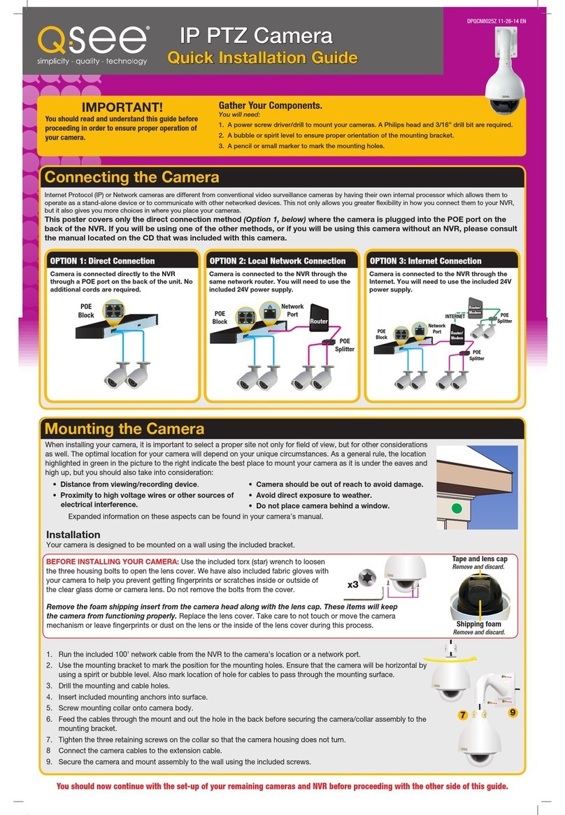
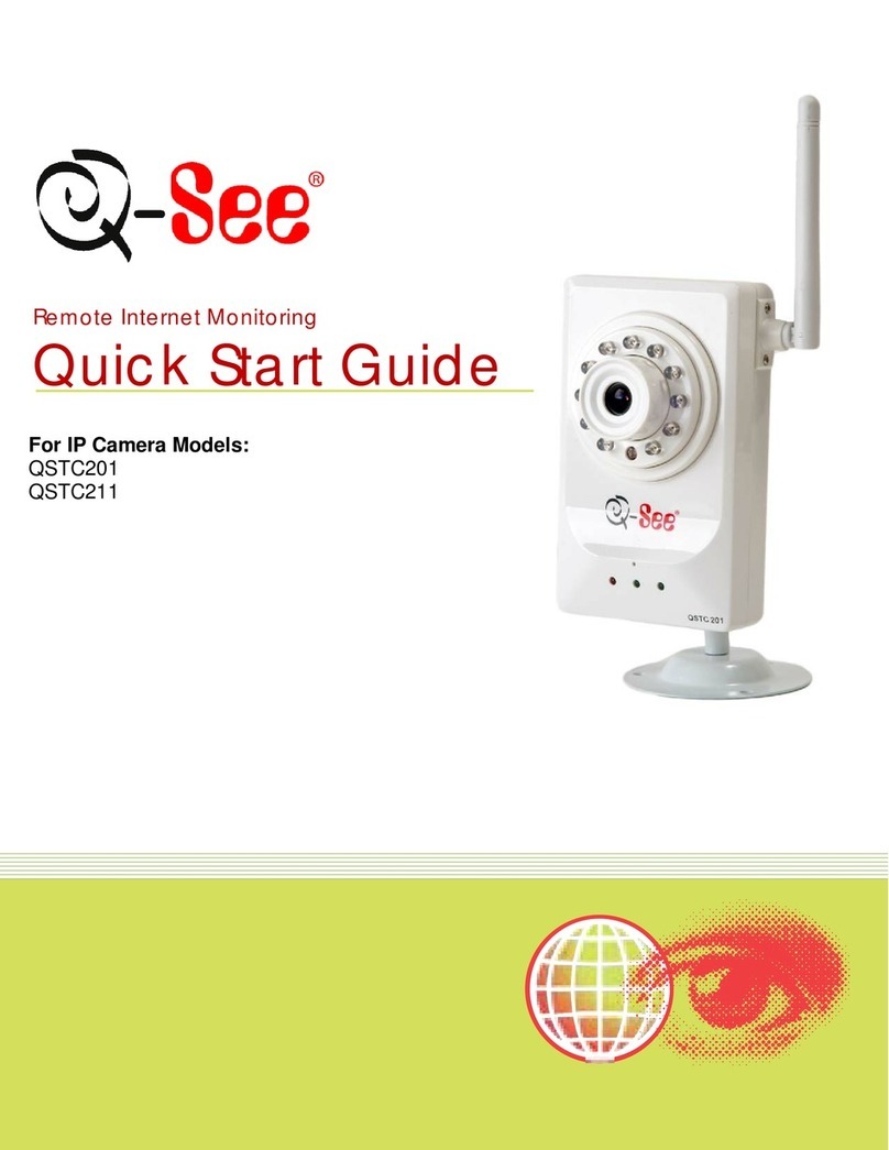
Q-See QSTC211 User manual

QSTC201/211
IP Camera
User’s Manual
Q-see Products
8015E.Crystal Dr
Anaheim, CA 92807
Website:
http://www.q-see.com
Phone: 877-998-3440 x 538
Rev082009

QSTC201/211 IP-CAMERA USER MANUAL
2
Before using this product
Before operating, we strongly advise users to read this manual and keep it
handy for later use.
This manual provides product instructions but we do not warranty the contents.
We reserve the right to amend typographical errors, and the product may
change due to software upgrades and product improvements. Any changes will
be published in the latest version without special notification.

QSTC201/211 IP-CAMERA USER MANUAL
3
Table of Contents
1 Introduction .................................................................................................................................................... 5
1.1 Product Summary.................................................................................................................. 5
1.2 Check package contents........................................................................................................ 5
1.3 IP-CAMERA interface introduction .........................................................................................6
1.3.1 Front View of IP-CAMERA ........................................................................................... 6
1.3.2 Back View of IP-CAMERA............................................................................................ 7
1.3.3 Top View of IP-CAMERA.............................................................................................. 8
2Installation ..................................................................................................................................................... 8
2.1 Attach IP-CAMERA to Ethernet network.................................................................................8
2.2 IP-CAM hardware installation................................................................................................. 9
2.3 Install CMS.......................................................................................................................... 10
2.3.1 Install process............................................................................................................ 12
3Internet Explorer Remote Access .......................................................................................................... 18
3.1 LAN..................................................................................................................................... 18
3.2 WAN.................................................................................................................................... 20
4Remote Preview ........................................................................................................................................... 22
4.1 The remote viewing interface is shown below:...................................................................... 22
4.2 Configuration: Video Stream, Enable Audio.......................................................................... 23
4.3 Using 2 Way Audio .............................................................................................................. 25
5Remote Live urveillance ......................................................................................................................... 26
5.1 Main Menu Setup ................................................................................................................ 26
5.2 System Configuration .......................................................................................................... 26
5.2.1 Server basic configuration.......................................................................................... 26
5.2.2 Date & Time configuration.......................................................................................... 27
5.2.3 SD Card..................................................................................................................... 28
5.3 Channel configuration.......................................................................................................... 28
5.3.1 Basic configuration .................................................................................................... 28
5.3.2 Image configuration ................................................................................................... 29
5.3.3 Network image configuration...................................................................................... 30
5.4 Alarm configuration.............................................................................................................. 31
5.4.1 Motion detection ........................................................................................................ 31
5.4.2 Motion alarm.............................................................................................................. 31
5.4.3 Motion Schedule........................................................................................................ 32
5.4.4 Sensor alarm ............................................................................................................. 33
5.4.5 Sensor schedule ........................................................................................................ 34
5.4.6 Other alarm................................................................................................................ 35
5.4.7 Alarm out ................................................................................................................... 36
QSTC201/211 IP-CAMERA USER MANUAL
4
5.5 Network configuration .......................................................................................................... 36
5.5.1 Basic configuration .................................................................................................... 36
5.5.2 IP configuration.......................................................................................................... 38
5.5.3 Wireless configuration................................................................................................ 39
5.5.4 DDNS configuration ................................................................................................... 40
5.6 User configuration................................................................................................................ 42
5.7 Notification configuration......................................................................................................44
5.8 Advanced configuration........................................................................................................ 45
5.8.1 Upgrade..................................................................................................................... 45
5.8.2 Security configuration ................................................................................................ 45
5.8.3 Default configuration .................................................................................................. 46
5.8.4 Reboot device............................................................................................................ 46
6Video earch.................................................................................................................................................. 47
7Mobile urveillance ................................................................................................................................... 48
7.1 Accessing by Phones with Windows Mobile Pro................................................................... 49
7.2 Accessing by Phones with Symbian ..................................................................................... 50
7.3 Accessing from iPhones....................................................................................................... 54
8Questions & Answers ................................................................................................................................. 62
9pecifications ................................................................................................................................................ 66
10 Q- ee Product Warranty .......................................................................................................................... 68

QSTC201/211 IP-CAMERA USER MANUAL
5
1
Introduction
1.1 Product Summary
This IP-CAMERA is a video surveillance device designed especially for CCTV
systems. It uses H.264 compression technology with a high-powered decoding chip,
and uses advanced IT technology, such as video encoding and decoding
technology, complies with the TCP/IP protocol, SoC, etc… to ensure this system is
stable and reliable. This unit consists of two parts: the IP-CAMERA device and
central management software. The central management software (CMS) allows you
to view and control multiple devices via internet or LAN and establishes a sound
surveillance system with unified management and remote operation for all the
devices in one network.
This product is widely used in banks, telecommunication systems, electricity power
departments, law systems, factories, storehouses, cities and so on. It is an ideal
choice for surveillance sites with middle or high risks.
1.2 Check package contents
The package should contain all the following:
Notice: the pictures below are only for reference; the actual items may
look different
1.IP-CAMERA
module
2.Power
adapter
3.User’s
manual
4.CMS CD 5.Alarm box
DVS
快
速
使
用
指
南
6.Cables 7.Audio
line
8. Camera
Stand
9. Hex key

QSTC201/211 IP-CAMERA USER MANUAL
6
Functions of accessories:
NO. Accessories Description
1 IP-CAMERA module The Camera
2 Power adapter The power adapter output DC 12V, which
supplies the power to the IP-CAMERA.
3 User manual The instructions for using the product
4 CD CD-ROM with software and manual
5. Alarm box Connect to alarm
6 Cable 1 Connect device to the alarm box
Cable 2 Connect the IP-CAMERA to the Internet
7 Audio line Connect to MIC & Headphones
8 Camera Stand Attach to back of IP Camera
9 Hex Key Adjust Screws on Camera Stand
1.3 IP-CAMERA interface introduction
1.3.1
Front View of IP-CAMERA
Notice: the pictures below are only for reference; the actual items may
look different

QSTC201/211 IP-CAMERA USER MANUAL
7
1.3.2
Back
Back Back
Back V
VV
View
iew iew
iew of
ofof
of
IP
IPIP
IP-
--
-CAM
CAMCAM
CAMERA
ERAERA
ERA
Item
Name Description
1 AUDIO IN/OUT Connect to MIC & Headphones
2 A ARM IN/OUT Connect to external alarm box
3 RESET Restore default settings
4 AN Connect to network
5 DC12V Power input
6 Thread hole Attaches IP-CAMERA to stand

QSTC201/211 IP-CAMERA USER MANUAL
8
1.3.3
Top
TopTop
Top
V
VV
View
iewiew
iew
of
ofof
of
IP
IPIP
IP-
--
-CAM
CAMCAM
CAMERA
ERAERA
ERA
2
Installation
2.1 Attach IP-CAMERA to Ethernet network
The connection of the digital video server is show below. Video input devices,
audio input devices and alarms should be connected first, then the power supply
is connected.
Fig 2-1 Connections

QSTC201/211 IP-CAMERA USER MANUAL
9
User can connect the PC (Surveillance Center) and IP-CAMERA as shown in the
above picture. Before connecting to PC, user needs to connect external devices,
and then connect the power. Connecting sensors or alarm boxes is optional and
depends on user’s needs.
The connection steps are shown below:
Step 1: Transfer line 1 connects to alarm box and IP-CAMERA first, and then
connect to alarm devices. (For more details please refer to IP-CAMERA
hardware installation 2.2).
Step 2: Transfer line 2 connects to MIC and Headphones
Step 3: Internet line connects to Internet broadband modem or router.
Step 4: Connect power cable to a power outlet
2.2 IP-CAM hardware installation
This section describes how to connect camera stand and alarm devices
(optional).
1.
1.1.
1.
Install IP-CAMERA
Step 1: Turn one end of the extension stand to the screw hole on the groove of
the base
Step 2: Turn the other end of the extension stand clockwise on the screw hole of
the IP-CAMERA and adjust it as shown in Fig 2-2
Fig 2-2 Install IP-CAM
Step 3: Adjust the IP-CAMERA and the stand to the desired position
2.
2.2.
2.
Connect to alarm devices as shown as Fig 2-3

QSTC201/211 IP-CAMERA USER MANUAL
10
Fig 2
Fig 2Fig 2
Fig 2-
--
-3
33
3
Connect to alarm box
Connect to alarm boxConnect to alarm box
Connect to alarm box
Connection parameter descriptions:
Name Description
GND Grounding
NC Normally Closed Alarm output
NO Normally Open Alarm output
5V 5V Power port
COM Public port used with NC or NO,connect to alarm output
Alarm IN Sensor input
3.
3.3.
3.
Check the Night Vision IR LEDS
Power on, the IP-CAMERA starts to work; user can see a circle of lights around
the LENS of IP-CAMERA which allow the user to view images clearly in the dark.
After the power is on, the IP-CAMERA starts to work.
2.3 Install CMS
After the IP-CAMERA is connected to the Ethernet, user can begin remote
monitoring and managing the device by using the client software or IE browser.
This chapter explains how to use the client software, and is the quick install
guide for the CMS. For operation and monitor setting details please refer to the
CMS user manual on the included CD.
Note: Before installing control center software in your computer, please

QSTC201/211 IP-CAMERA USER MANUAL
11
make sure all anti-virus software in the computer is disabled so that CMS
can install correctly.
System requirements
•
Supported Operating Systems:
Operating
system
Comments
Windows XP Windows XP SP2 or most recent patch,
DirectX 9.0c or above
Windows Vista Windows Vista
DirectX 10.c
Computer hardware requirements
Please make sure the system is running well and the computer is
compatible
:
•
Recommended PC Specifications – 4 channels
Item Specification
CPU Intel Pentium 3.0 GHz or AMD 3000+
Memory 1GB
HDD 160GB
•
Recommended PC Specifications -9 channels:
Item Specification
CPU Intel Core 2 Duo 1.8 GHz or AMD Dual core 3800+
Memory 1GB
HDD 250GB
•
Recommended PC Specifications -16 channels:
Item Specification
CPU Intel Core 2 Duo 2.2 GHz or AMD Dual core 3800+
Memory 2GB

QSTC201/211 IP-CAMERA USER MANUAL
12
HDD 250GB
Notice:
The above recommended specifications are for CIF resolution.
The AMD hyper-3800+ and X64 series chips have not been tested;
If user wants to have real-time live view with CIF resolution
(352x240), the max connection number is 16 on one computer;
If user wants to have real-time live view with D1 resolution
(704x480), the max connection number is 4 on one computer.
2.3.1 Install process
1. Run the “Control Center” from software CD, double click “Setup.exe” file,
Figure2-4 window will pop up:
Figure2-4 Welcome menu
2. Click “Next” to enter the next step, shown as Figure2-5:

QSTC201/211 IP-CAMERA USER MANUAL
13
Figure2-5 Choose the installation destination
3. The default installation destination folder is “C:\Program Files”, user can
click “Browse” button to change it. After selecting the destination, click “Next” to
enter the next step shown as Fig 2-6:
Figure2-6 selects a folder to install in
4. Click “Next” to start installing and display Fig 2-7:
Figure2-7 the rate of installation progress
5. The installation is complete shown as Fig 2-8:

QSTC201/211 IP-CAMERA USER MANUAL
14
Figure2-8 Setup Complete
6. Click “Finish” to complete setup, and see the “Control Center” icon
on the desktop.
7. Double click CMS icon to start the software, the default user name is
“system”, and password is “123456”, user can change it as shown in the
corresponding chapter, for detailed introductions refer to “user manager” in user
manual. The CMS preview interface is shown as Fig 2-9:

QSTC201/211 IP-CAMERA USER MANUAL
15
Figure2-9 Preview interface
8. Add device:
User can add video monitor device or sub region under the heading of add
region.
Step 1: Enter into the System Configuration menu, click 'Device
Manager , input the region name in 'Region' textbox. Refer to Fig 2-10:
Fig 2-10 Add region

QSTC201/211 IP-CAMERA USER MANUAL
16
Step 2: Click button; 'Add Device' dialog box will pop up refer to
Fig 2-11:
Fig 2-11 Add device
Step 3: If the monitor device exists with the PC at the same LAN, click the
“Search device” button, CMS will search for the compatible device in LAN and
list the details in the “Device search” dialog box. Double click an item, it will be
added to the information list on the right refer to Fig 2-12:
Fig 2-12 Device search
Note: CMS and IP Tool can’t run at the same time or the device
information won’t search and display.
Step 4: In the “Channel Group” dialog box select a device or area, click
or icon, user can rename or delete the selected device or area.
Select channel, user can rename the displayed name in this channel.
After successfully adding a device, user can re-group the channel of all
devices. Following these steps:
Step 1: change the interface to “Channel Group”
Notice: Please close the live preview when previewing channel or
recording in the device list.

QSTC201/211 IP-CAMERA USER MANUAL
17
Step 2: Clicking ‘Device Manager enters into “Device manager”,
click icon, add group name. Refer to Fig 2-13
Fig 2-13 Add group
Step 3: Select the channel in the “Device list” edit box, click icon,
and add the channel into “Channel group” edit box.

QSTC201/211 IP-CAMERA USER MANUAL
18
3
Internet Explorer Remote Access
The network service default settings are shown below:
IP address: 192.168.0.201
Subnet Mask: 255.255.255.0
Gateway: 192.168.0.1
HTTP: 80
Data port: 9008
When using the IP-CAMERA for the first time, please connect the device using
the above default settings, and reconfigure the setting according to your network.
Here we are using IE browser (above 6.0 versions) as an example; for operation
using CMS please refer to CMS user’s manual.
3.1 LAN
Step 1: Manually setup the IP address of the PC, the network segment should
be as same as the default settings of IP-CAMERA. Right click “My Network
Places” icon on the desktop, select “properties”; right click “Local Area
Connection” on the pop-up window, and then select “properties”. Select “Internet
Protocol (TCP/IP)” in the “General” tab, click “properties”, manually input
network address information of the PC in the pop up window, refers to figure 3-1:
Fig 3-1 PC network setting

QSTC201/211 IP-CAMERA USER MANUAL
19
Step 2: Open the IE Browser, input the default address of IP-CAMERA and
confirm, the IE browser will download an Active X control automatically. If IE
browser can’t download the Active X control, please refer to Q4 of Chapter 9
Step 3: After downloading the Active X control, the login dialog box will pop up
as shown in figure 3-2:
Fig 3-2 Login dialog box
Step 4: Input user name and password in the login dialog box, click “OK” button
to enter into the live view interface refer to Figure 3-3. User can manage and
setup the IP-CAMERA, such as changing IP address etc.
Fig 3-3 IE browser preview interface
Note: The default user name is “admin” and password is 123456

QSTC201/211 IP-CAMERA USER MANUAL
20
3.2 WAN
Setting up the router:
Step1: Connect according to above steps in LAN, enter into System
Configuration—Network configuration—Basic configuration, setup the port
numbers refer to Fig 3-4:
Fig 3-4 Port setup
Step 2: Enter into System Configuration—Network configuration—IP
configuration, change IP address refer to Fig 3-5:
Fig 3-5 IP setup
Note:The steps above should be saved after changing the port and IP
address. Log back into the device with the saved setting.
This manual suits for next models
1
Table of contents
Other Q-See IP Camera manuals

Q-See
Q-See QCW4MP1PT-AU User manual

Q-See
Q-See QSTC201 User manual

Q-See
Q-See QC-SERIES User manual

Q-See
Q-See QCN8025Z User manual

Q-See
Q-See QSTC201 User manual

Q-See
Q-See QT SERIES User manual

Q-See
Q-See EasyView QN6401X User manual

Q-See
Q-See QC-SERIES User manual

Q-See
Q-See QCN7001B User manual

Q-See
Q-See QTN8019B User manual