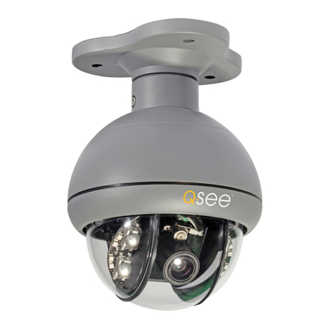
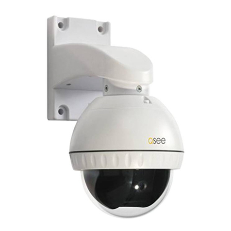
Q-See QTH7212P User manual

1
QTH7212P
USER MANUAL

2 3
24/7 TECHNICAL RESOURCES,
KNOWLEDGE BASE AND MORE
www.Q-See.com/Support
Live chat is available at the same address from Monday to Friday 6am to 7pm
Saturday and Sunday 9am to 5pm. All times are Pacific.
© 2015 Q-See. Reproduction in whole or in part without written permission is prohibited. All
rights reserved. This manual and software and hardware described herein, in whole or in part,
may not be reproduced, translated, or reduced to any machine-readable form without prior
written approval.
Trademarks: All brand names and products are trademarks or registered trademarks of their
respective owners.
Q-See is a registered trademark of DPS, Inc.
Disclaimer: The information in this document is subject to change without notice. The
manufacturer makes no representations or warranties, either express or implied, of any kind
with respect to completeness of its contents.
Manufacturer shall not be liable for any damages whatsoever from misuse of this product.
Thank You for Choosing a Q-See Product!
All of our products are backed by a conditional service warranty covering all hardware for 24
months from the date of purchase. Additionally, our products also come with a free exchange
policy that covers all manufacturing defects for one month from the date of purchase.
Permanent upgrading service is provided for the software and is available at www.Q-See.com.
Be certain to make the most of your warranty by completing the registration form online. In
addition to warranty and technical support benefits, you’ll receive notifications of product
updates along with free downloadable firmware updates for your DVR. Register today at
www.Q-See.com!
Please see the back of this manual for exclusions.
2-year Limited Warranty
Thank you for choosing Q-See to provide for your security needs, and welcome to the
Q-See community! We stand behind the quality of all of our products, and we want you to
know that we’re here to help you should you ever need assistance with your Q-See purchase.
To receive full warranty benefits and lightning fast support, register your products at
www.Q-See.com.
Be sure to keep your receipt, invoice, purchase order, or order confirmation it in a safe place
- you’ll need a copy of as a proof of purchase to be able to obtain warranty service.
What does my warranty cover?
Q-See warrants that your product is free from defects in materials and workmanship, with the
exceptions stated below. If your product is not operating properly due to a product defect, Q-See
will repair or replace your product according to the guidelines stated in this warranty policy.
What doesn’t my warranty cover?
Your warranty doesn’t cover the following:
• Misuse
• Accident
• Modification or alteration to hardware or software, including the removal of any Q-See
logos or brand identification
• Cut or spliced cables or wires
• Products that have been painted
• Wires coated in insulation, caulk, or other materials
• Tampering or unauthorized repairs
• Unsuitable physical or operating environment beyond product specifications
• Improper maintenance
• Incorrect power supplies being used with products
• Power fluctuations or surges – please be sure to use a surge protector
• Failure caused by a non-Q-See product being used with your Q-See products
• Loss of data – please be sure to regularly back up any recorded data on your hard drive
that you want to keep to a separate storage product, like an external hard drive or a
computer.
How long does my warranty last?
From the date of purchase, your products will be covered by your warranty for two (2) years.
Warranty service does not extend your warranty.If you decide to employ an installer to set up
and install your system, we are not responsible for installation costs, and won’t be able to
reimburse you for any installation fees.
For the full Q-See warranty terms and policies, please visit www.Q-See.com/Support.
Q-SEE PRODUCT WARRANTY
Rev. 1.0 5/19/15

4 5
FEATURES
n
Care should be taken during transportation, storage and installation of this camera
to avoid rough handling, dropping, or other abuse in order to prevent damage to the
optics or components inside the camera.
n
Camera should be installed in accordance with electrical standards including keeping
the camera and cable away from high voltage, using a transient voltage surge
protector (UL-1449) and using only the rated power supply.
n
Do not use strong or abrasive cleaners on camera body or lens. Use a damp cloth
for cleaning the housing and a lens cloth for the optics.
n
Do not attempt to disassemble the camera beyond removing the case to adjust
settings. Only authorized, trained technicians should service this camera.
n
The camera should not be immersed in water and should be mounted in a sheltered
location. Do not point camera directly at the sun or other strong light source.
This manual is written for the QTH7212P pan-tilt camera and was accurate at
the time it was completed. However, because of our ongoing effort to constantly
improve our products, additional features and functions may have been added
since that time and on-screen displays may change. We encourage you to visit our
website at www.Q-See.com to check for the latest product announcements. You
can also find technical details and an electronic version of this manual on our online
Knowledge base online at www.Q-See.com/support.
Throughout the manual we have highlighted warnings and other important
information that will assist you in operating your new system in a safe and trouble-
free manner. Please take the time to read and follow all instructions and pay
attention to alerts as shown below:
INTRODUCTION
NOTE! Text in blue boxes with the Information icon offer additional guidance
and explanations about how to make the most out of your system.
IMPORTANT! Red boxes with this icon indicate warnings. To prevent
possible injury or damage to the product, read all warnings before use.
For your safety and to protect your camera
To prevent damage to your Q-See product or injury to yourself or to others, read
and understand the following safety precautions in their entirety before installing or
using this equipment.
WARNING! ELECTRIC SHOCK RISK!
Your camera offers the following features:
nCompatible with QTH-series BNC HD DVRs
nHigh quality video using 1/4” Aptina Sensor with NextChip 2431 processor to
produce 720p high definition video.
nWeatherproof IP65 Rating
nRS485 control.
n128 preset positions - 80 preset positions and 48 special function settings.
n3.6mm fixed lens.
n360° continuous horizontal rotation with 90° vertical movement.
nLow-noise camera rotation motor.
nFully-functional built-in decoder - all data is saved inside of the module to retain
settings in case of power loss.
nRotation/tilt speed: 25°/second
nDecoder’s all-in-one integrated design ensures high reliability.
Image
Sensor
1/4” Aptina
Digital
Signal
Processor
NextChip 2431
Signal
System
NTSC
Lens 3.6mm
Effective
Pixels (HxV)
1280x720
Usable
Illumination
.01 lux
Scanning 2:1 Interlace
Sync.
System
Internal
Horizontal
System
720p / 1 Megapixel
Shutter
Speed
NTSC=1/60 ~1/100,000 sec
S/N Ratio > 52dB
White
Balance
Auto
BLC Auto
AGC Auto
Video
Output
1.0V P-P,75Ω BNC
Input
Current
12V 1.2A
Power
Consump-
tion
<6W
Protection
Rating
IP65
Operating
Temp
14°F to 122°F (-10°C to 50°)
(relative humidity: up to 95%)
Storage
Temp
-22°F to 158°F (-30°C to
70°C)
Color Black
Control
Protocol
Pelco-D and Pelco-P
Baud Rate 2400b/4800b/9600b
SPECIFICATIONS

6 7
SETTING CAMERA ADDRESS
Remove CollarRemove Collar
CHANGING ADDRESS SETTINGS
If you need to change your camera’s
address, they are made using a DIP
(Dual In-line Package) switch panel
located within the camera itself (see
picture, right). It is easier to do this
before connecting the camera, because
the switch panel may be inaccessible
because of location, position, etc.
To access the panel, remove the clear
dome by first twisting the collar around
the dome counterclockwise. Take care
to not scratch the clear dome while
removing it. The circuit board on which
the DIP switches are mounted is located
below the camera head.
DIP switches are binary - meaning
that they are either On (“1”) or Off
(“0”). Different combinations of ones
and zeroes on the board produce
different settings. See the next page for
instructions and examples.
ON
12345678
Camera Address
CAMERA ADDRESS SETTINGS
The illustration below shows the settings for a camera with an address of “1”
Address Switch
(8 digits)
Code 1 2 3 4 5 6 7 8
1 1 0 0 0 0 0 0 0
2 0 1 0 0 0 0 0 0
3 1 1 0 0 0 0 0 0
4 0 0 1 0 0 0 0 0
5 1 0 1 0 0 0 0 0
6 0 1 1 0 0 0 0 0
7 1 1 1 0 0 0 0 0
8 0 0 0 1 0 0 0 0
9 1 0 0 1 0 0 0 0
10 0 1 0 1 0 0 0 0
11 1 1 0 1 0 0 0 0
12 0 0 1 1 0 0 0 0
13 1 0 1 1 0 0 0 0
14 0 1 1 1 0 0 0 0
15 1 1 1 1 0 0 0 0
16 0 0 0 0 1 0 0 0
Address
Unlike conventional security cameras, PTZ cameras require an address in order for
them to properly operate. This address is only important if your system will be using
more than one Pan-Tilt or Pan-Tilt-Zoom camera. If two cameras on a system have
the same address, they will both follow the same instructions - meaning that at
least one of them won’t be pointing in the right place. The camera address is set
to 1 by default. If you are only using a single PTZ camera you will likely not have to
make any changes and you may proceed to the next section. Please consult your
DVR’s manual for required settings.
Unlike conventional Analog PTZ cameras, baud rates and communications
protocols are automatically recognized by BNC HD cameras and DVRs so there is
no need to make settings for these. To change the camera’s address, move
the appropriate switch(es) up or down.
For example, to change the address
from “1” to “2”, Switch 1 will need to be
moved down (OFF) and Switch 2 will
need to be moved up (ON).

8 9
STEP 2. Connect the power lead
on the other end of the video/
power cable to a power adapter
or power distribution panel.
Make certain that the power
supply is rated for 12 volts
and 800mA to 1.5A.
STEP 3. Connect the BNC
connector on that same end of
the cable to a Video In port on
the back of the DVR.
CONNECTING THE CAMERA
Before you can operate the camera, you must connect it to a system which can
support PTZ operations. There are three sets of connectors - power, video and
the bare control wires. This latter connection is covered on the next page. We
recommend connecting the camera (at least temporarily) to the DVR to test your
settings and connections before mounting it in its final location.
CAMERA CABLE CONNECTIONS
STEP 1. Connect the BNC, power and RS485 leads from the camera to the
matching connectors on the extension cable (Note: these may need to be
purchased separately if your camera was not included as part of a bundle
package).
AUDIO IN VIDEO IN
1 3
2 4
1 3
2 4
IMPORTANT! When connecting the
power and video cable between the
camera and the DVR, the “male” power
end (red plug) connects to the matching
power lead on the camera.
PTZ CONTROL CONNECTION
In addition to connecting the power and video leads to the camera, you must also
connect the two control wire leads to the RS485 ports in the alarm block on the
back of the DVR. These blocks can vary in layout as shown below, but the ports
used by your DVR are generally labelled “RS485”, “RS422”, “PTZ” or “P/Z”.
As seen in the picture on the right, the wire leads from the
camera are two different colors and are labeled. They are
also pre-installed into a block which plugs into a matching
receptacle on the extension cable. There are matching wire
leads (see inset) at the other end of the extension cable
which must be inserted into the ports on the back of the
DVR. In the case of the RS485 ports being marked as
positive (+) and negative (-), the wire designated RS485A
(orange tip) is the positive lead while the wire marked
RS485B (yellow tip) is to go into the negative port. PTZ
blocks on your DVR either have small screws to above
each port to secure the wire or require a lock above the
port to be depressed with an object like a small screw
driver in order to fully insert the wire. In the latter, when the
lock is released, an internal clamp will keep the wire firmly
secured in the port. If the wire can easily be removed from
the port, then it isn’t secure and you can experience control
difficulties until it is properly attached.
Serial PortSerial Port AdvancedAdvanced
P.T.ZP.T.Z
DefaultDefault ApplyApply ExitExit
CH Enable Address Baud Rate Protocol Simulative Cruise
1
2
3
4
CH Enable Address Baud Rate Protocol Simulative Cruise
1
2
3
4
AllAll
11
22
33
44
24002400
96009600
96009600
96009600
PELCODPELCOD
PELCOPPELCOP
PELCOPPELCOP
PELCOPPELCOP
96009600 PELCOPPELCOP
Some examples of PTZ blocks. One using screws (left) and two using spring-loaded locks.
To connect your camera to the DVR
over a distance, you will need to use
both a video/power cable and a pair of
24-gauge wires to connect to the alarm
block. If your camera came as part of a
package, these wires may be included
separately or as part of the video and
power cable.
You can now plug the camera’s power adapter into a surge protector and turn it on.
To protect your investment, we STRONGLY recommended using a surge protector
that is UL-1449 rated, for a clamping voltage of 330 or lower, a Joule rating of at
least 400 and a response time of 10 nanoseconds or less.
Space permitting, multiple PTZ cameras may be connected to the same ports.
They will each require a different address which is set up using the DIP switches as
covered in the previous section.
Once you have made your connections, you will need to make settings on the DVR
in order to control it. You will need to consult your DVR’s manual for this procedure,
but a sample screen (from a Q-See QT-series DVR) is shown on the right.
Video (BNC)
Power
RS485

10 11
When installing your camera, it is important to select a proper site not only for field
of view, but for other considerations as well:
Distance from viewing/recording device. The further the camera is from the DVR or
monitor, the higher the chances of signal degradation. Typical 75Ω Video Cable
provides acceptable signal at distances up to 200’ (30m). At greater distances,
UL-Listed shielded RG59 should be used. The camera’s power supply should be
located as near to the camera as possible when the distance exceeds 200’ as
the power level will drop over extended distances resulting in a decrease in video
quality.
Do not place near high voltage wires or other sources of electrical interference. Electrical
interference will degrade the quality of the signal.
Place camera out of reach to avoid damage.
Avoid direct exposure to weather. Do not place the camera where rain or snow will
hit the lens directly nor should the camera be placed so that the sun or bright light
shines directly into the lens. Your camera is weatherproof, but it will not work when
submerged in water. Ensure that all power and video connections are not directly
exposed to water and are protected from the elements.
Do not place camera behind a window. If there is a light source behind the camera, it
can cause a reflection in the window that will obscure events on the other side of
the glass.
Light levels should be approximately the same between camera and target area. A
camera in a brightly-lit area looking into a shaded area, or vice versa, may produce
inadequate results.
The above are guidelines and the optimal location for your camera will depend on
INSTALLING THE CAMERA
your unique circumstances. As a general
rule, the locations highlighted in green in
the picture to the right indicate the best
locations to mount your camera. Both
locations are sheltered from rain or snow
and offer good sight lines to allow your
camera to monitor a wide area. Because
your camera is weatherproof, it requires
less protection than weather-resistant
cameras and it can be placed in more
exposed locations if needed. Keep in
mind that this camera is designed to
operate between 14°F to 122°F (-10°C
to 50°) with a relative humidity of up to
MOUNTING THE CAMERA
STEP 1. Run the power/video/data extension
cable from the DVR to the camera’s
location.
Wall Mount: Remove the bottom plate
from the wall bracket’s arm.
STEP 2. Use the desired mounting bracket
to mark the position for the mounting
holes. Drill the mounting holes with a
3/16” (5mm) drill bit. If needed, the hole
for the cables should also be drilled at
this time. It is best to drill a large enough
hole to prevent the cable from catching
on anything and allowing the cable
extending from the camera to be easily
pushed through.
STEP 3. Insert the included anchors into
the mounting holes.
STEP 4. Pass the cable ends from the wall/
ceiling through the bracket.
Wall Mount: Cables should only be
passed through the hole in the back of
the bracket. The green block should be
passed through the hole first.
STEP 5. Mount the bracket to the surface.
STEP 6. Connect the camera’s cable ends to
those on the extention cable.
Wall Mount: Pass the cable ends from
the camera through the hole at the front
of the bracket.
Make sure that the cables aren’t
crimped inside the bracket - push
excess cable back into the wall/ceiling.
STEP 7. Secure the camera to the mount
using the three short bolts.
Wall Mount: Replace the bottom plate
on the support arm and secure with
included screws.
IMPORTANT! Don’t let the
cables be pinched, tightly bent
or otherwise constricted as
part of final installation as this
can damage the cable over time leading to
signal loss or potential fire hazard.
Take care to ensure a clear work area
below the camera mounting point during
installation as a falling camera can cause
injury or damage.
95%) and consider wind chill and other environmental factors when selecting your
location.
Your camera comes with both a ceiling and wall mount. Where you locate your
camera will determine which mount you will need to use. The mounting surface
must be sturdy and able to hold at least five times the camera’s total weight.
12 13
Q-See Model
Number
QS50B (50’)
QS100B (100’)
QSVRG60 (60’)
QSVRG100 (100’)
QSVRG200 (200’)
QS59500 (500’)
QS591000 (1000’)
Maximum Run Length 100’ 200’ 800’
Quality Output Standard High High
Type 75Ω Video Cable RG-59 RG-59
Shielded No Yes - UL Rated Yes - UL Rated
Plenum Rated No No No
Pre-Attached Connector
Video BNC BNC None
Audio N/A N/A N/A
Power 2.1mm 2.1mm None
Usage Indoor/Outdoor · Do
not run inside walls or
underground
Indoor/Outdoor · In-wall or along wall
For best results, it is highly recommended that you use RG-59 cable.
NOTE: To extend the RS485 data cable needed to control the camera, you may use any 24
gauge wire, including Cat 5.
To maintain video quality:
· Video quality is always enhanced by using shielded cables.
· Always check state and local laws before installing cameras. (2011 NEC 820.44)
· To prevent video signal loss, run one continuous cable between the camera and DVR for
best results. If more length is required, use the minimum number of inter-connection points
possible.
Other notes:
· If a cable run exceeds 800ft, we recommend using RG-6 coaxial cable which is available at
most retail building supply companies.
· If your home or business is pre-wired with CAT-5 cable, then you can run up to 1000ft.
Powered video baluns are required for easy installation.
WHICH CABLE TO USE?
Your cabling needs will depend on the distance between your camera and your DVR. Q-See
offers several cables to fit specific needs. These may be purchased from the same location as
where you bought your camera, or on our website: www.q-seestore.com
OPERATION
The your camera can be controlled manually through a PTZ keyboard (if supported by your
DVR), or by using the PTZ controls on the DVR to which it is connected. Depending on the
software used, it is also possible to control the PTZ camera remotely when you are logged into
the DVR via the Internet, a remote monitoring program or a smartphone app.
You can also program a cruise - also called “scan” or “tour” on some systems - so that the
camera will perform a set search pattern of the surrounding area. Up to 128 preset points can
be stored on the camera. As mentioned in the section on Connecting the Camera, you will
need to consult your DVR’s manual for specifics on how to enable your system to control your
camera. That manual should also contain instructions on how to program points and cruises
for the camera to use.
GENERAL CRUISE SETUP PROCEDURE
SaveSave
Zoom
Focus
Iris
Zoom
Focus
Iris
Speed: 5Speed: 5
No.No.
11
02020101 0303 0404 0505 0606 0707 0808 AllAll
While each DVR system is different in the
specifics of how to set up a scan, there
are general similarities. Most involve the
process of pivoting the camera to the desired
starting point and saving that point. Then, by
selecting one or more points for the camera
to move to in sequence, a scan path is built
which is then saved. Often, multiple paths
can be saved within the DVR, which can be
selected for later use.
These points can be set using a special PTZ
keyboard, or by using the PTZ controls on
the DVR itself. Two such on-screen interfaces
are shown at right; the QT-Series (top) and
QC-series (bottom). In both examples,
directional control is achieved by using
the DVR’s mouse to click on one of the
directional arrows. As long as the arrow is
held, the camera will move in that direction.
There are no horizontal stops and the camera
can rotate continuously if desired. The
camera’s elevation is limited to 90°.
On both control panels there are controls for zoom, focus and iris (light level). The QD6531Z
has a 3x optical zoom lens which will adjust between 5 and 15mm. The camera has an auto-
focus feature and is not user adjustable. Objects closer than 20” (50cm) will be blurry due to
the limits of the automatic focus. Likewise, the camera automatically adjusts the iris internally
and that setting is not manually changeable by the user.
Of the 128 presets available on the camera, presets 1-80 may be used for defining camera
positions. The remaining 48 are commands for the camera. Of that latter group, Preset 95 is the
most useful as it will erase previously configured presets.

14 15
EXAMPLE 1: SETTING A CRUISE
This example is based on using a QT-Series DVR without an attached PTZ keyboard. Your
DVR’s specific commands may differ slightly. Please consult your system’s manual.
STEP 1. In your DVR’s PTZ settings
window, select the Advanced tab and
then Preset 1.
STEP 2. Rotate the camera to the desired
position using the arrow controls.
STEP 3. Click Save
STEP 4. Select Preset 2.
STEP 5. Rotate camera to desired
second location.
STEP 6. Click Save
You may repeat Steps 4-6 for additional
positions if desired.
STEP 7. Return to the PTZ window and
click on the Cruise button for your
channel.
STEP 8. Click Add.
STEP 9. Double-click on the new cruise
setting to begin loading your presets.
STEP 10. Click on the +button to open
the Preset pop-up window and select
your starting preset point, speed and
stop time.
Speed: 1-8 with 8 being the fastest
Time: This is the time the camera will
stay pointed at this location.
Serial PortSerial Port AdvancedAdvanced
P.T.ZP.T.Z
DefaultDefault
SettingSetting
SettingSetting
SettingSetting
SettingSetting
SettingSetting
SettingSetting
SettingSetting
SettingSetting
SettingSetting
SettingSetting
SettingSetting
SettingSetting
SettingSetting
SettingSetting
SettingSetting
SettingSetting
SettingSetting
SettingSetting
SettingSetting
SettingSetting
SettingSetting
SettingSetting
SettingSetting
SettingSetting
ApplyApply ExitExit
CH Preset Cruise Track
1
2
3
4
5
6
7
8
CH Preset Cruise Track
1
2
3
4
5
6
7
8
SaveSave
Zoom
Focus
Iris
Zoom
Focus
Iris
Speed: 5Speed: 5
No.No.
11
02020101 0303 0404 0505 0606 0707 0808 AllAll
Start TrackStart Track
Start Auto ScanStart Auto Scan
Start CruiseStart Cruise
Preset
Cruise
Preset
Cruise
Speed: 5Speed: 5
preset 101preset 101
02020101 0303 0404 0505 0606 0707 0808 AllAll
Zoom
Focus
Iris
Zoom
Focus
Iris
STEP 11. Repeat for each preset - up to a maximum of 16 per cruise.
STEP 12. Click OK save your settings and close the windows until you reach the PTZ
Settings window. Click Apply to save all of the settings.
STEP 13. Open the PTZ controls from the Control Bar, select your cruise in the pull-down
and click
to begin.
EXAMPLE 2: SETTING A TRACK
An alternate method is to utilize the Track settings - also found in the Advanced tab. Click
the Track button for the right channel, use the directional controls to point the camera at your
desired starting point and then click Start Record. The DVR will then record your movements,
including delays at selected spots. Click Stop Record to end. Clicking on Start Track in the
PTZ control window will start the camera on its track.
TROUBLESHOOTING
Problem Solution
No picture or unstable image Check both the power and video
connections to the camera.
The on-screen image is blurry. 1. Check for fingerprints or dirt on the lens.
2. Check menu settings.
The on-screen image is dim. 1. Check for fingerprints or dirt on the lens.
2. Check monitor settings
The on-screen image is dark. 1. Adjust the monitor contrast settings.
The screen flickers. Camera may be facing sun, television or
computer monitor.
The camera is not working properly, is hot,
smells or is producing smoke.
DISCONNECT CAMERA FROM POWER
SUPPLY IMMEDIATELY!
1. Check that correct power supply is in use.
2. Send camera out for repair.

16
Table of contents
Other Q-See Security Camera manuals

Q-See
Q-See QSPDC User manual

Q-See
Q-See QPSCD NV User manual

Q-See
Q-See SDI Cameras User manual

Q-See
Q-See QCW3MP1B User manual

Q-See
Q-See QSIPO26X User manual

Q-See
Q-See Plus Series User manual

Q-See
Q-See QSDS1349D User manual

Q-See
Q-See QCN8009D User manual

Q-See
Q-See QSLO2712 User manual

Q-See
Q-See QCW2MP User manual

Q-See
Q-See QSDS14273 User manual

Q-See
Q-See QSICC2PK User manual

Q-See
Q-See QCW4MP1PT User manual

Q-See
Q-See QSDS13358A User manual

Q-See
Q-See QD6003D User manual

Q-See
Q-See QSMCC User manual

Q-See
Q-See QTN8043B User manual

Q-See
Q-See QSDS1312D User manual

Q-See
Q-See QSOCWC User manual

Q-See
Q-See QCW3MP16 User manual