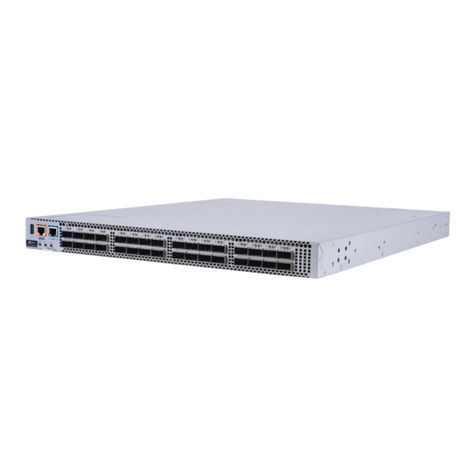
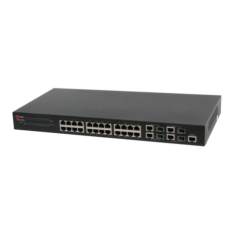
q-Tech QSW-4700 Series Installation and operating manual

HARDWARE INSTALLATION AND REFERENCE GUIDE
www.qtech.ru
QSW-4700 Series Switches
Hardware Installation and Reference Guide

QSW-4700 Series Switches Hardware Installation and Reference Guide
Product Overview
2
Contents
1. PRODUCT OVERVIEW 7
1.1. QSW-4700 Series Switches 7
1.2. QSW-4700-28TX 8
1.2.1. Specifications 8
1.2.2. Appearance 10
1.2.2.1. Front Panel 10
1.2.2.2. Back Panel 11
1.2.3. Power Supply Module 11
1.2.4. Cooling 11
1.2.5. LED 12
1.3. QSW-4700-52TX 13
1.3.1. Specifications 13
1.3.2. Appearance 15
1.3.2.1. Front Panel 15
1.3.2.2. Back Panel 16
1.3.2.3. Power Supply 16
1.3.3. Cooling 16
1.3.4. LED 17
1.4. QSW-4700-28TX-POE 18
1.4.1. Specifications 18
1.4.2. Appearance 21
1.4.2.1. Front Panel 21
1.4.2.2. Back Panel 22
1.4.3. Power Supply 22
1.4.4. Cooling 22
1.4.5. LED 22
1.4.6. LED Mode Button 24
1.5. QSW-4700-52TX-POE 24
1.5.1. Specifications 24
1.5.2. Appearance 27
1.5.2.1. Front Panel 27
1.5.2.2. Back Panel 27
1.5.3. Power Supply 28
1.5.4. Cooling 28
1.5.5. LED 28
1.5.6. LED Mode Button 30

QSW-4700 Series Switches Hardware Installation and Reference Guide
Product Overview
3
1.6. QSW-4700-28F 30
1.6.1. Specifications 30
1.6.2. Appearance 32
1.6.2.1. Front Panel 32
1.6.2.2. Back Panel 33
1.6.3. Power Supply 33
1.6.4. Cooling 33
1.6.5. LED 34
1.7. QSW-4700-52F 35
1.7.1. Specifications 35
1.7.2. Appearance 37
1.7.2.1. Front Panel 37
1.7.2.2. Back Panel 38
1.7.3. Power Supply 38
1.7.4. Cooling 38
1.7.5. LED 39
1.8. Power Supply Module 40
1.8.1. QSW-M-4700-AC Module 40
1.8.1.1. Specifications 40
1.8.1.2. Features 41
1.8.1.3. LED 42
1.8.2. QSW-M-4700-DC Module 42
1.8.2.1. Specifications 42
1.8.2.2. Features 43
1.8.2.3. LED 43
1.8.3. QSW-M-4700-POE-AC Module 44
1.8.3.1. Specifications 44
1.8.3.2. Features 45
1.8.3.3. LED 45
1.8.4. QSW-M-4700-POE-DC Module 46
1.8.4.1. Specifications 46
1.8.4.2. Features 47
1.8.4.3. LED 47
1.8.5. QSW-M-4700-HPOE-AC Module 47
1.8.5.1. Specifications 48
1.8.5.2. Features 49
1.8.5.3. LED 49

QSW-4700 Series Switches Hardware Installation and Reference Guide
Product Overview
4
2. PREPARING FOR INSTALLATION 50
2.1. Safety Precautions 50
2.1.1. General Safety Precautions 50
2.1.2. Handling Safety 50
2.1.3. Electric Safety 50
2.1.4. Electrostatic Discharge Safety 51
2.1.5. Laser Safety 51
2.2. Installation Environment Requirements 51
2.2.1. Ventilation Requirements 51
2.2.2. Temperature/Humidity Requirements 51
2.2.3. Cleanliness Requirements 52
2.2.4. Anti-interference Requirements 53
2.2.5. Grounding Requirements 53
2.2.5.1. Safe Grounding 53
2.2.5.2. Lightning Grounding 53
2.2.5.3. EMC Grounding 53
2.2.6. Lightning Protection Requirements 54
2.2.7. EMI Requirements 54
2.3. Fiber-Optic Cable Connection Requirements 54
2.4. Tools 54
3. INSTALLING THE SWITCH 55
3.1. Installing Procedure 55
3.2. Before You Begin 56
3.3. Mounting the Switch 56
3.3.1. Mounting the Switch in a Rack 56
3.3.2. Mounting the Switch on the Wall 57
3.3.3. Installing the Switch on a Workbench 58
3.4. Installing and Removing a Power Supply Module 58
3.4.1. Installing the AC Power Supply Module 58
3.4.2. Removing the AC Power Supply Module 59
3.4.3. Installing the DC Power Supply Module 59
3.4.4. Removing the DC Power Supply Module 60
3.5. Grounding the Switch 61
3.6. Connecting Cables 61
3.6.1. Bending Steps 62
3.7. Cable Bundling 62
3.7.1. Bundling Steps 62
QSW-4700 Series Switches Hardware Installation and Reference Guide
Product Overview
5
3.8. Verifying Installation 62
4. VERIFYING OPERATING STATUS 63
4.1. Setting up Configuration Environment 63
4.1.1. Setting up Configuration Environment 63
4.1.2. Connecting an Ethernet Cable 63
4.1.3. Setting Parameters 63
4.2. Powering on Switch 65
4.2.1. Checklist before Power-on 65
4.2.2. Checklist after Power-on (Recommended) 65
5. MONITORING AND MAINTENANCE 66
5.1. Monitoring 66
5.1.1. LED 66
5.1.2. CLI Commands 66
5.2. Maintenance 66
5.2.1. Cooling System Maintenance 66
5.2.2. Power Supply Module Maintenance 66
5.2.3. Replacing Lithium Battery 67
5.2.4. Replacing Fuses 67
6. TROUBLESHOOTING 68
6.1. Troubleshooting Flowchart 68
6.2. Troubleshooting 68
6.2.1. Fault 1: The login password is forgotten. 68
6.2.2. Fault 2: The AC power module does not work. 69
6.2.3. Fault 3: The serial port console has no output. 69
6.2.4. Fault 4: The serial port console output is garbled. 69
6.2.5. Fault 5: The link cannot be set up on the fiber port. 69
7. APPENDIX 71
7.1. Connectors and Media 71
7.1.1. 1000BASE-T/100BASE-TX/10BASE-T 71
7.1.2. Fiber Connection 72
7.1.3. Lightening Protection 72
7.1.3.1. Installing AC Power Arrester (Lightning Protection Power Strip) 72
7.1.3.2. Installing the Ethernet Port Arrester 73
7.1.3.3. Ethernet port arrester: 74
7.2. Cabling 74
7.3. Requirements for Cable Bend Radius 75
7.4. Requirements for Fiber Bend Radius 75

QSW-4700 Series Switches Hardware Installation and Reference Guide
Product Overview
6
7.5. Precautions for Bundling up Cables 75
7.6. Site Selection 77
8. СПИСОК ПОДДЕРЖИВАЕМОГО ФУНКЦИОНАЛА 79
9. ОБЩАЯ ИНФОРМАЦИЯ 80
9.1. Замечания и предложения 80
9.2. Гарантия и сервис 81
9.3. Техническая поддержка 81
9.4. Электронная версия документа 81

QSW-4700 Series Switches Hardware Installation and Reference Guide
Product Overview
7
1. PRODUCT OVERVIEW
QTECH QSW-4700 series switches are new generation layer 3 switches, providing high
performance, consolidated security and multiple services. The switches are mainly applied to
the access layer to provide line-rate switching and complete QoS policies, prioritizing some
traffic over others to ensure important data transmission without lantency. The switches also
support a wide variety of Ethernet interfaces with flexible media options for network construction.
1.1. QSW-4700 Series Switches
Model
10/100/1000
Base-T
Adaptive
Ethernet
Port
GE
SFP
Port
10GE
SFP+
Port
Manage
ment
Port
USB
Port
Con
sole
Port
RPS
QSW-4700-28TX
24
N/A
4
1
1
1
Dual
Power
Suppli
es
QSW-4700-52TX
48
N/A
4
1
1
1
Dual
Power
Suppli
es
QSW-4700-28TX-
POE
24 (PoE+
Capable)
N/A
4
1
1
1
Dual
Power
Suppli
es
QSW-4700-28F
N/A
24
4
1
1
1
Dual
Power
Suppli
es
QSW-4700-52F
N/A
48
4
1
1
1
Dual
Power
Suppli
es
QSW-4700-52TX-
POE
48 (PoE+
Capable)
N/A
4
1
1
1
Dual
Power
Suppli
es

QSW-4700 Series Switches Hardware Installation and Reference Guide
Product Overview
8
Note:
This is a Class A product. In a domestic environment this product may cause radio interference.
In this case, users are advised to take proper measures against the interference.
An SFP+ port supports both 10GBase-R and 1000Base-X.
The PoE+ port is backward compatible with the PoE standard.
•Management port: The management port is a 10/100/1000Base-T Ethernet port that
uses an RJ-45 connector. This port is connected to an Ethernet port of a PC with an
Ethernet cable for program downloading. You can manage and maintain the switch
remotely by connecting the management port to the Ethernet port of a PC with an
Ethernet cable.
•USB port: The USB port is the interface into which you plug your USB storage device
for online upgrade or log storage.
•Console port: The console port is an RS-232 port that uses an RJ45 connector. The
console port is used to connect a PC directly to the management system for debugging,
configuration, maintenance, management and program loading.
1.2. QSW-4700-28TX
1.2.1. Specifications
Model
QSW-4700-28TX
CPU
Dual-core CPU with the clock speed of 1.2 GHz
BOOTROM
16 MB
Flash Memory
2 GB
SDRAM
1 GB
SFP Module
Type
•SFP+ Port:
•SFP Modules and SFP BIDI Modules
•SFP+ Modules, SFP+ Cables and SFP+ BIDI Modules.
•See Chapter 7 for details.
Note:
The module types may update without prior notification. Please
contact Qtech for details.
Power Supply
Module Slots
2

QSW-4700 Series Switches Hardware Installation and Reference Guide
Product Overview
9
Model
QSW-4700-28TX
Power Supply
Module
•Model: QSW-M-4700-AC
AC Input
Rated Voltage Range: 100 V AC to 240 V AC
Maximum Voltage Range: 90 V AC to 264 V AC
Frequency: 50 Hz/60 Hz
Rated Current Per Circuit: 3 A
•Model: QSW-M-4700-DC
DC Input
Rated Voltage Range: -48 V DC to -60 V DC
Maximum Voltage Range: -36 V DC to -75 V DC
Rated Current Per Circuit: 5 A
SFP+ Port
10GBase-R Capable
1000Base-X Capable
RTC
Supported
PoE
Not Supported
Power
Consumption
< 40 W
Operating
Temperature
0ºC to 45ºC (32ºF to 113 ºF) at a height below 1800 m (1.12 miles)
above the sea level
At a height ranging from 1800 m (1.12 miles) to 5000 m (3.11 miles)
above the sea level, the maximum operating temperature decreases
by 1°C (1.8°F) every time the altitude increases by 220 m
(721.78 ft.).
Storage
Temperature
-40ºC to 70ºC (-40ºF to 158ºF)
Operating
Humidity
10% to 90% RH (non-condensing)
Operating
Height
0 to 5000 m (3.11 miles) above the sea level

QSW-4700 Series Switches Hardware Installation and Reference Guide
Product Overview
10
Model
QSW-4700-28TX
Storage
Humidity
5% to 95% RH (non-condensing)
Fan
Fan Speed Control
Fan Fault Alarming
Temperature
Alarming
Supported
EMI
Certification
GB9254-2008CLASS A
Safety
Regulation
Compliance
GB4943-2011
Dimensions (W
x D x H)
442 mm x 420 mm x 43.6 mm (17.40 in. x 16.54 in. x 1.72 in.)
Weight
4 kg (8.82 lbs.)
1.2.2. Appearance
The front panel of the QSW-4700-28TX switch provides 24 10/100/1000Base-T Ethernet ports,
four 10GE SFP+ ports, one management port, one Console port and one USB port. The back
panel has two power supply module slots.
Figure 1-1 QSW-4700-28TX Switch Appearance
1.2.2.1. Front Panel
Figure 1-2 Front Panel of QSW-4700-28TX

QSW-4700 Series Switches Hardware Installation and Reference Guide
Product Overview
11
1. System Status LED
2. MGMT Port LED
3. PWR1 Status LED
4. PWR2 Status LED
5. USB Port
6. Console Port
7. Management Port
8. 10/100/1000Base-T Ethernet Port
9. 10GE SFP+ Port
10. Port Status LED
1.2.2.2. Back Panel
Figure1-3 Back Panel of QSW-4700-28TX
1. Grounding Stud
2. Power Supply Module Slot 1 (A filler panel is required if the slot is vacant.)
3. Power Supply Module Slot 2 (A filler panel is required if the slot is vacant.)
1.2.3. Power Supply Module
The QSW-4700-28TX switch supports dual power supply modules. See Chapter 1.13 for details
about the power supply modules.
The switch can be powered on by either one power supply module or dual power supply modules.
If both power supply modules are used, the switch works in the power redundancy mode.
1.2.4. Cooling
The QSW-4700-28TX switch adopts a left-to-right and front-to-right airflow to ensure normal
operation. Maintain a minimum clearance of 100 mm (3.94 in.) around the device for air
circulation.
Figure 1-4 Airflow Direction

QSW-4700 Series Switches Hardware Installation and Reference Guide
Product Overview
12
1.2.5. LED
Function
Panel ID
Color
Status
System Status LED
Status
Off
System is not powered on.
Blinking
Green (3
Hz)
System is being initialized.
Continuous blinking indicates a fault.
Blinking
Green (10
Hz)
System is being located.
Solid
Green
System is operating normally.
Solid
Yellow
The temperature at the air intake and
exhaust vents exceeds the threshold.
Solid Red
1. The temperature at the air intake
and exhaust vents well exceeds
the threshold.
2. The system is not functioning
properly.
Power Supply Status
LED
PWR1/PW
R2
Off
The power supply module is not
seated.
Solid
Green
The power supply module is seated
and providing power to the switch.
Solid
Yellow
The model of the power supply
module is not supported or cannot be
read.
Solid Red
The redundant power supply module
is not functioning properly or not
connected with the AC power cord.
Management Port
LED
MGMT
Off
No link is detected for this port.
Solid
Green
The port has made a successful
1000 Mbps link.
Blinking
Green
The port is sending and receiving
traffic at 1000 Mbps.
Solid
Yellow
The port has made a successful
10/100 Mbps link.
Blinking
Yellow
The port is sending and receiving
traffic at 10/100 Mbps.

QSW-4700 Series Switches Hardware Installation and Reference Guide
Product Overview
13
Function
Panel ID
Color
Status
10GE SFP+ Port LED
25F to 28F
Off
No link is detected for this port.
Solid
Green
The port has made a successful 1/10
Gbps link.
Blinking
Green
The port is sending and receiving
traffic at 1/10 Gbps.
10/100/1000Base-T
Ethernet Port LED
1F to 24F
Off
No link is detected for this port.
Solid
Green
The port has made a successful
10/100/1000 Mbps link.
Blinking
Green
The port is sending and receiving
traffic at 10/100/1000 Mbps.
1.3. QSW-4700-52TX
1.3.1. Specifications
Model
QSW-4700-52TX
CPU
Dual-core CPU with the clock speed of 1.2 GHz
BOOTROM
16 MB
Flash Memory
2 GB
SDRAM
1 GB
SFP Module
Type
•SFP+ Port:
•SFP Modules and SFP BIDI Modules
•SFP+ Modules, SFP+ Cables and SFP+ BIDI Modules.
•See Chapter 7 for details.
Note:
The module types may update without prior notification. Please
contact Qtech for details.
Power Supply
Module Slots
2

QSW-4700 Series Switches Hardware Installation and Reference Guide
Product Overview
14
Model
QSW-4700-52TX
Power Supply
Module
•QSW-M-4700-AC
AC Input
Rated Voltage Range: 100 V AC to 240 V AC
Maximum Voltage Range: 90 V AC to 264 V AC
Frequency: 50 Hz/60 Hz
Rated Current Per Circuit: 3 A
•QSW-M-4700-DC
DC Input
Rated Voltage Range: -48 V DC to -60 V DC
Maximum Voltage Range: -36 V DC to -75 V DC
Rated Current Per Circuit: 5 A
SFP+ Port
10GBase-R Capable
1000Base-X Capable
RTC
Supported
PoE
Not supported
Power
Consumption
< 55 W
Operating
Temperature
0ºC to 45ºC (32ºF to 113 ºF) at a height below 1800 m (1.12 miles)
above the sea level
At a height ranging from 1800 m (1.12 miles) to 5000 m (3.11
miles) above the sea level, the maximum operating temperature
decreases by 1°C (1.8°F) every time the altitude increases by
220 m (721.78 ft.).
Storage
Temperature
-40ºC to 70ºC (-40ºF to 158ºF)
Operating
Humidity
10% to 90% RH (non-condensing)
Operating
Height
0 to 5000 m (3.11 miles) above the sea level
Storage
Humidity
5% to 95% RH (non-condensing)

QSW-4700 Series Switches Hardware Installation and Reference Guide
Product Overview
15
Model
QSW-4700-52TX
Fan
Fan Speed Control
Fan Fault Alarming
Temperature
Alarming
Supported
EMI
Certification
GB9254-2008CLASS A
Safety
Regulation
Compliance
GB4943-2011
Dimensions
(W x D x H)
442 mm x 420 mm x 43.6 mm (17.40 in. x 16.54 in. x 1.72 in.)
Weight
4.3 kg (9.48 lbs.)
1.3.2. Appearance
The front panel of the QSW-4700-52TX Ethernet switch provides 48 10/100/1000Base-T
Ethernet ports, four 10GE SFP+ ports, one management port, one Console port and one USB
port. The back panel has two power supply module slots.
Figure 1-5 QSW-4700-52TX Switch Appearance
1.3.2.1. Front Panel
Figure 1-6 Front Panel of QSW-4700-52TX
1. System Status LED
2. Management Port LED

QSW-4700 Series Switches Hardware Installation and Reference Guide
Product Overview
16
3. PWR1 Status LED
4. PWR2 Status LED
5. USB Port
6. Console Port
7. Management Port
8. 10/100/1000Base-T Ethernet Port
9. 10GE SFP+ Port
10. Port LED
1.3.2.2. Back Panel
Figure 1-7 Back Panel of QSW-4700-52TX
1. Grounding Stud
2. Power Supply Module Slot 1 (A filler panel is required if the slot is vacant.)
3. Power Supply Module Slot 2 (A filler panel is required if the slot is vacant.)
1.3.2.3. Power Supply
The QSW-4700-52TX switch supports dual power supply modules. See Chapter 1.13 for details
about the power supply modules.
The switch can be powered on by either one power supply module or dual power supply modules.
If both power supply modules are used, the switch works in the power redundancy mode.
1.3.3. Cooling
The QSW-4700-52TX switch adopts a left-to-right and front-to-right airflow to ensure normal
operation. Maintain a minimum clearance of 100 mm (3.94 in.) around the device for air
circulation.
Figure 1-8 Airflow Direction

QSW-4700 Series Switches Hardware Installation and Reference Guide
Product Overview
17
1.3.4. LED
Function
Panel ID
Color
Status
System Status
LED
Status
Off
System is not powered on.
Blinking
Green (3 Hz)
System is being initialized.
Continuous blinking indicates a
fault.
Blinking
Green
(10 Hz)
System is being located.
Solid Green
System is operating normally.
Solid Yellow
The temperature at the air intake
and exhaust vents exceeds the
threshold.
Solid Red
1. The temperature at the air intake
and exhaust vents well exceeds the
threshold.
2. The system is not functioning
properly.
Power Supply
Status LED
PWR1/PW
R2
Off
The power supply module is not
seated.
Solid Green
The power supply module is seated
and providing power to the switch.
Solid Yellow
The model of the power supply
module is not supported or cannot
be identified.
Solid Red
The redundant power supply
module is not functioning properly
or not connected with the AC power
cord.
Management Port
LED
MGMT
Off
No link is detected for this port.
Solid Green
The port has made a successful
1000 Mbps link.

QSW-4700 Series Switches Hardware Installation and Reference Guide
Product Overview
18
Function
Panel ID
Color
Status
Management Port
LED
MGMT
Blinking
Green
The port is sending and receiving
traffic at 1000 Mbps.
Solid Yellow
The port has made a successful
10/100 Mbps link.
Blinking
Yellow
The port is sending and receiving
traffic at 10/100 Mbps.
10GE SFP+ Port
LED
49F to 52F
Off
No link is detected for this port.
Solid Green
The port has made a successful
1/10 Gbps link.
Blinking
Green
The port is sending and receiving
traffic at 1/10 Gbps.
10/100/1000Base-
T Ethernet Port
LED
1F to 48F
Off
No link is detected for this port.
Solid Green
The port has made a successful
10/100/1000 Mbps link.
Blinking
Green
The port is sending and receiving
traffic at 10/100/1000 Mbps.
1.4. QSW-4700-28TX-POE
1.4.1. Specifications
Model
QSW-4700-28TX-POE
CPU
Dual-core CPU with the clock speed of 1.2 GHz
BOOTROM
16 MB
Flash Memory
2 GB
SDRAM
1 GB

QSW-4700 Series Switches Hardware Installation and Reference Guide
Product Overview
19
Model
QSW-4700-28TX-POE
SFP Module
Type
•SFP+ Port:
•SFP Modules and SFP BIDI Modules
•SFP+ Modules, SFP+ Cables and SFP+ BIDI Modules.
•See Chapter 7 for details.
Note:
The module types may update without prior notification. Please
contact Qtech for details.
Power Supply
Module Slots
2
Power Supply
Module
•QSW-M-4700-POE-AC
AC Input
Rated Voltage Range: 200 V AC to 240 V AC
Maximum Voltage Range: 176 V AC to 264 V AC
Frequency: 50 Hz/60 Hz
Rated Current Per Circuit: 8 A
•QSW-M-4700-POE-DC
DC Input
Rated Voltage Range: -48 V DC to -60 V DC
Maximum Voltage Range: -38 V DC to -75 V DC
Rated Current Per Circuit: 20 A
Power Supply
Module
•QSW-M-4700-HPOE-AC
AC Input
Rated Voltage Range: 200 V AC to 240 V AC
Maximum Voltage Range: 176 V AC to 264 V AC
Frequency: 50 Hz/60 Hz
Rated Current Per Circuit: 8 A
SFP+ Port
10GBase-R Capable
1000Base-X Capable
RTC
Supported

QSW-4700 Series Switches Hardware Installation and Reference Guide
Product Overview
20
Model
QSW-4700-28TX-POE
PoE
•All RJ45 ports are PoE+ capable and each port provides up
to 30 W of power. The maximum power depends on the
configured power supply.
•Note:
•The PoE+ port is compliant with both the PoE
(IEEE802.3af) and PoE+ (IEEE802.3at) standards.
•The maximum number of PoE devices supported by the
switch is determined by the available PoE consumption of
the switch and the actual PoE consumption of each device.
The PoE port is compliant with Alternative A.
Power
Consumption
Without PoE Load: < 65 W
With PoE Full Load: < 810 W
Operating
Temperature
0ºC to 45ºC (32ºF to 113 ºF) at a height below 1800 m (1.12 miles)
above the sea level
At a height ranging from 1800 m (1.12 miles) to 5000 m (3.11
miles) above the sea level, the maximum operating temperature
decreases by 1°C (1.8°F) every time the altitude increases by
220 m (721.78 ft.).
Storage
Temperature
-40ºC to 70ºC (-40ºF to 158ºF)
Operating
Humidity
10% to 90% RH (non-condensing)
Operating
Height
0 to 5000 m (3.11 miles) above the sea level
Operating
Humidity
5% to 95% RH (non-condensing)
Fan
Fan Speed Control
Fan Fault Alarming
Temperature
Alarming
Supported
EMI
Certification
GB9254-2008CLASS A
This manual suits for next models
6
Table of contents
Other q-Tech Switch manuals

q-Tech
q-Tech QSW-2800 series User manual

q-Tech
q-Tech QSW-4600 Series Installation and operating manual

q-Tech
q-Tech QSW-8200 series User manual

q-Tech
q-Tech QSW-4600-12T-POE Installation and operating manual

q-Tech
q-Tech QSW-7600 Series Installation and operating manual

q-Tech
q-Tech QSW-6200-32T Installation and operating manual

q-Tech
q-Tech QSW-6900-32H Series User manual

q-Tech
q-Tech QSW-6300 Series Installation and operating manual

q-Tech
q-Tech QSW-6900-56LF Series Installation and operating manual