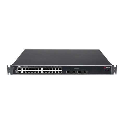
q-Tech QSW-4600 Series Installation and operating manual
HARDWARE INSTALLATION AND REFERENCE GUIDE
www.qtech.ru
QSW-4600 Series Switch
Hardware Installation and Reference Guide V1.0

QSW-4600 Series Switch Hardware Installation and Reference Guide 2
www.qtech.ru
Copyright Statement
QTECH©2017
QTECH reserves all copyrights of this document. Any reproduction, excerption, backup, modification, transmission,
translation or commercial use of this document or any portion of this document, in any form or by any means, without the
prior written consent of QTECH is prohibited.
Exemption Statement
This document is provided “as is”. The contents of this document are subject to change without any notice. Please obtain
the latest information through the QTECH website. QTECH endeavors to ensure content accuracy and will not shoulder
any responsibility for losses and damages caused due to content omissions, inaccuracies or errors.

QSW-4600 Series Switch Hardware Installation and Reference Guide 3
www.qtech.ru
Preface
Thank you for using our products. This manual will guide you through the installation of the device.
This manual describes the functional and physical features and provides the device installation steps, hardware
troubleshooting, module technical specifications, and specifications and usage guidelines for cables and connectors.
Audience
It is intended for the users who have some experience in installing and maintaining network hardware. At the same time, it
is assumed that the users are already familiar with the related terms and concepts.
Obtaining Technical Assistance
QTECH Website: http://www.qtech.ru
Technical Support: https://helpdesk.qtech.ru/
Related Documents
Documents
Description
Configuration Guide
Describes network protocols and related mechanisms that supported by the
product, with configuration examples.
Command Reference
Describes the related configuration commands, including command modes,
parameter descriptions, usage guides, and related examples.
Symbol Conventions
Means reader take note. Notes contain helpful suggestions or references.
Means reader be careful. In this situation, you might do something that could result in equipment damage or loss of
data.

QSW-4600 Series Switch Hardware Installation and Reference Guide 4
www.qtech.ru
1 Product Overview
The QSW-4600 series switch is a next-generation intelligent switch that features high performance, high security, multiple
services and ease of use to meet the needs of the current networks. The QSW-4600 series switch can provide the
complete end-to-end Quality of Service (QoS), flexible and abundant security policies and policy-based network
management for various networks. It is greatly ideal for such applications as campus network, enterprise network,
government network, service network, residential broadband access and business building network, providing high-speed,
high-efficiency, secure and intelligent access solutions.
Table 1-1 QSW-4600
Model
10/100/1000
Base-T
Auto-sensing
Ethernet Port
SFP+
Port
1000Base-X
SFP Port
Console
Port
USB
Port
Expansion
Module
Slot
Pluggable
Power
Slot
QSW-4600-28ТX
24
4
1
1
N/A
N/A
N/A
QSW-4600-52ТX
48
4
1
1
N/A
N/A
N/A
QSW-4600-28ТX-POE
24 (PoE+)
2
2 (Combo)
1
1
2
Dual
QSW-4600-52ТX-POE
48 (PoE+)
2
2 (Combo)
1
1
2
Dual
The SFP+ ports support both 10Gbase-R and 1000base-X modules.
The SFP ports support both 1000 base-X and 100base-X modules.
1000Base-T is compatible with 100Base-TX and 10Base-T in the downlink direction.
1.1 QSW-4600-28ТX
Technical Specifications
Model
QSW-4600-28ТX
EEE
Supported
PoE
Not supported
Power
Consumption
≤24W
Operating
Temperature
0℃to 50℃

QSW-4600 Series Switch Hardware Installation and Reference Guide 5
www.qtech.ru
Storage
Temperature
-40℃to 70℃
Operating Humidity
10% to 90%
Storage Humidity
5% to 95%
Fan
Speed adjustment and fault alarm
Temperature
Warning
Supported
EMCStandards
GB9254-2008
Security Standards
GB4943-2011
Dimensions
(W x D x H)
440 mm x 260 mm x 43.6 mm
Weight
≤3.5 kg
The QSW-4600-28ТX switch is a class A product. In a domestic environment, this product may cause radio
interference in which case the user may be required to take adequate measures.

QSW-4600 Series Switch Hardware Installation and Reference Guide 6
www.qtech.ru
Product Appearance
The QSW-4600-28ТX full gigabit Ethernet switch provides 1 RJ45 Console port, 24 RJ45 10/100/1000Base-T
auto-sensing Ethernet ports and 4 SFP+ ports on the front panel.
Front Panel
Figure1-1 Front Panel of QSW-4600-28ТX
Note
1. System status LED
2. Console port
3. 10/100/1000 Base-T auto-sensing Ethernet port
4. 10/100/1000 Base-T copper port status LED
5.10G SFP+ port
6.10G SFP+ port
7. SFP+ fiber port status LED
8. SFP+ fiber port status LED

QSW-4600 Series Switch Hardware Installation and Reference Guide 7
www.qtech.ru
Back Panel
Figure 1-2 Back Panel of QSW-4600-28ТX
Note
1. Grounding pole
2. Three-hole AC power receptacle
3. Power cord retention clips
Power Supply
The QSW-4600-28ТX switch adopts AC or HVDC power input.
AC input
Rated voltage range: 100V to 240V, 50/60 Hz
Maximum voltage range: 90V to 264V, 47 Hz to 63 Hz
Frequency: 50/60 Hz
Rated current: 1.5A
Power cord specification: 10A
HVDC input
Voltage range: 192V to 290V
Current range: 0.1A to 0.5A
Heat Dissipation
The QSW-4600-28ТX full gigabit switch is designed with fans. To ensure good dissipation, sufficient space (10 cm
distance from both sides and the back panel of the chassis) should be reserved for ventilation. It is recommended to clean
the switch at regular intervals (like once every 3 months). Especially, avoid dust from blocking the screen mesh on the
back of the cabinet; otherwise, the temperature of the device may go too high and affects the performance.
When installing the device, sufficient ventilation space (1 U (44.45 mm) distance from the adjacent device) should be
reserved for the purpose of heat dissipation.
LEDs
LED
Panel Marker
Status
Indication
System status LED
Status
Blinking green
The system is being initialized.

QSW-4600 Series Switch Hardware Installation and Reference Guide 8
www.qtech.ru
Solid green
The switch is operational.
Solid red
Over-temperature, the system will reboot.
The switch is faulty.
10/100/1000 Base-T copper
port status LED
1-24
Off
The port is not connected.
Solid green
The port is connected at 1000 Mbps.
Solid yellow
The port is connected at 10/100 Mbps.
Blinking
Data are being transceived at the port.
SFP+ fiber port status LED
25F-28F
Off
The port is not connected.
Solid green
The port is connected.
Blinking
Data are being transceived at the port.
1.2 QSW-4600-52ТX
Technical Specifications
Model
QSW-4600-52ТX
CPU
Single-core CPU with the clock speed of 1.0G
BOOTROM
/
Flash Memory
256MB
SDRAM
DDRIII 512MB
SFP+ Port
Supports 10Gbase-R and 1000Base-X SFP+ modules.
Power Supply
AC input
Rated voltage range: 100V to 240V
Maximum voltage range: 90V to 264V
Frequency: 50/60 Hz
Rated current: 1.5A
HVDC input
Voltage range: 192V to 290V

QSW-4600 Series Switch Hardware Installation and Reference Guide 9
www.qtech.ru
Current range: 0.5A to 0.8A
EEE
Supported
PoE
Not supported
Power
Consumption
≤50W
Operating
Temperature
0℃to 50℃
Storage
Temperature
-40℃to 70℃
Operating Humidity
10% to 90%
Storage Humidity
5% to 95%
Fan
Speed adjustment and fault alarm
Temperature
Warning
Supported
EMCStandards
GB9254-2008
Security Standards
GB4943-2011
Dimensions
(W x D x H)
440 mm x 260 mm x 43.6 mm
Weight
≤4 kg
The QSW-4600-52ТX switch is a class A product. In a domestic environment, this product may cause radio
interference in which case the user may be required to take adequate measures.
Product Appearance
On the front panel, the QSW-4600-52ТX full gigabit Ethernet switch provides 1 RJ45 Console port, 48 RJ45
10/100/1000Base-T auto-sensing Ethernet ports and 4 SFP+ ports.

QSW-4600 Series Switch Hardware Installation and Reference Guide 10
www.qtech.ru
Front Panel
Figure1-3 Front Panel of QSW-4600-52ТX
Note
1. System status LED
2. Console port
3.10/100/1000 Base-T auto-sensing Ethernet port
4.10G SFP+ port
5.10G SFP+ port
6. 10/100/1000 Base-T copper port status LED
7. SFP+ port status LED
Back Panel
Figure 1-4 Back Panel of QSW-4600-52ТX
Note
1. Grounding pole
2. Three-hole AC power receptacle
3. Power cord retention clips
Power Supply
The QSW-4600-52ТX switch adopts AC or HVDC power input.
AC input
Rated voltage range: 100V to 240V, 50/60Hz
Maximum voltage range: 90V to 264V, 47 Hz to 63 Hz
Frequency: 50/60 Hz
Rated current: 1.5A
Power cord specification: 10A
HVDC input
Voltage range: 192V to 290V
Current range: 0.5A to 0.8A

QSW-4600 Series Switch Hardware Installation and Reference Guide 11
www.qtech.ru
Heat Dissipation
The QSW-4600-52ТX full gigabit switch is designed with fans. To ensure good dissipation, sufficient space (10 cm
distance from both sides and the back panel of the chassis) should be reserved for ventilation. It is recommended to clean
the switch at regular intervals (like once every 3 months). Especially, avoid dust from blocking the screen mesh on the
back of the cabinet; otherwise, the temperature of the device may go too high and affects the performance.
LEDs
LED
Panel Marker
Status
Indication
System status LED
Status
Blinking green
The system is being initialized.
Solid green
The switch is operational..
Solid red
Over-temperature, the system will reboot.
The switch is faulty.
10/100/1000 Base-T copper
port status LED
1-48
Off
The port is not connected.
Solid green
The port is connected at 1000 Mbps.
Solid yellow
The port is connected at 10/100 Mbps
Blinking
Data are being transceived at the port.
SFP+ fiber port status LED
49F-52F
Off
The port is not connected.
Solid green
The port is connected.
Blinking
Data are being transceived at the port.
1.3 QSW-4600-28ТX-POE
Technical Specifications
Model
QSW-4600-28ТX-POE
CPU
Single-core CPU with the clock speed of 1.0G

QSW-4600 Series Switch Hardware Installation and Reference Guide 12
www.qtech.ru
BOOTROM
/
Flash Memory
512MB
SDRAM
DDRIII 512MB
Optical Module
See Appendix B.
The supported module type may change at any time. Contact QTECH for
details.
Expansion Module
QSW-M-4600-GT
QSW-M-4600-SFP+
SFP Port
100Base-X
1000Base-X
SFP+ Port
10GBase-R
1000Base-X
RPS Type
Dual power supplies
Power Supply
QSW-M-4600-POE-AC
1) AC
Rated voltage range: 100V to 240V
Rated current range: 3.5A to 7A
Frequency range: 50/60 Hz
2) HVDC
Voltage range: 192 V to 290V
Rated current range: 2.5 A to 3.5 A
QSW-M-4600-HPOE-AC
1) AC
Rated voltage range: 100V to 240V

QSW-4600 Series Switch Hardware Installation and Reference Guide 13
www.qtech.ru
Frequency range: 50/60 Hz
Rated current: 10A
2) HVDC
Voltage range: 192V to 290V
Rated current: 10A
QSW-M-4600-POE-DC
Voltage range: -72V to -36V
Rated current: 16.5 A
EEE
Supported
PoE
All the RJ45 ports are PoE-capable with the maximum power output of 30W.
The available number of PDs is determined by PSE output power and PD input
power in practice.
Power Consumption
Less than 38W without extension cards or PoE load
Less than 850W with PoE full load
Temperature
Operating temperature: 0 ºC to 50ºC
Storage temperature: -40 ºC to 70ºC
Humidity
Operating humidity: 10% to 90%
Storage humidity: 5% to 95%
Fan
Speed adjustment and fault alarm
Temperature Warning
Supported
EMC Standards
GB9254-2008
Safety Standards
GB4943-2011

QSW-4600 Series Switch Hardware Installation and Reference Guide 14
www.qtech.ru
Dimensions (W x D x H)
440 mm x 320 mm x 44 mm
Weight
5.8 kg (with package)
The QSW-4600-28ТX-POE switch is a class A product. In a domestic environment, this product may cause radio
interference in which case the user may be required to take adequate measures.
Product Appearance
On the front panel, the QSW-4600-28ТX-POE Ethernet switch provides 24 10/100/1000Base-T Ethernet ports, 2 GE SFP
fiber/copper combo ports, 2 10G SFP+ ports and 1 Console port. On the back panel, it provides 2 power module slots and
2 expansion module slots.
Front Panel
Figure 1-5 Front Panel of QSW-4600-28ТX-POE
Note:
System status LED
1. Expansion module 1 status LED
2. Expansion module 2 status LED
3. Power module 1 status LED
4. Power module 2 status LED
5. PoE status LED
6. Copper port status LED
7. Fiber port status LED
8. PoE mode switch-over button
9. Console port
10. USB port
11. 10/100/1000Base-T auto-sensing Ethernet port
12. 100/1000Base-X SFP port
13. SFP+ port
Long press PoE Mode Switch-Over Button for above 2 seconds to switch the display mode between PoE mode and
port rate mode.
Back Panel

QSW-4600 Series Switch Hardware Installation and Reference Guide 15
www.qtech.ru
Figure 1-6 Back Panel of QSW-4600-28ТX-POE
Note:
Expansion module 1 slot
Expansion module 2 slot
Power module 1 slot
Power module 2 slot
Grounding pole
Power Supply
The QSW-4600-28ТX-POE supports 2 power modules with AC or DC input. For the detailed power specification, see the
following tables.
Model
QSW-M-4600-POE-AC
Platform
QSW-4600-28ТX-POE
QSW-4600-52ТX-POE
Rated Voltage Range
100V to 240V
50/60 Hz
Maximum Voltage
Range
90 V to 264 V
50/60 Hz
PoE Power
Single power supply: 370W
Dual power supplies: 740W
Hot Swapping
Supported

QSW-4600 Series Switch Hardware Installation and Reference Guide 16
www.qtech.ru
Redundant Power
Supplies
1+1
Over-Voltage
Protection
54 V: -60V to -57V
12 V: 13.4V to 16V
Over-Current
Protection
54V: 8A to 10A
12V: 12A to 16A
Over-Temperature
Protection
Supported
Load-Balanced Power
Supply
Supported
Power Supply Mix
Supported with QSW-M-4600-POE-DC
Power Cord
10A
Dimensions
(W x D x H)
224.5 mm x 90 mm x 40 mm (with connecting fingers and handles)
195.4 mm x 90 mm x 40 mm (without connecting fingers or handles)
Weight
1.6 kg
Model
QSW-M-4600-POE-DC
Platform
QSW-4600-28ТX-POE
QSW-4600-52ТX-POE
Rated Voltage Range
-72V to -36V

QSW-4600 Series Switch Hardware Installation and Reference Guide 17
www.qtech.ru
PoE Power
Single power supply: 370 W
Dual power supplies: 740 W
Hot Swapping
Supported
Redundant Power
Supplies
1+1
Over-Voltage
Protection
54 V: -66V to -58V
12 V: 13.2V to 15.6V
Over-Current
Protection
54V: 7.8A to 10A
12 V: 11A to 14A
Over-Temperature
Protection
Supported
Load-Balanced Power
Supply
Supported
Power Supply Mix
Supported with QSW-M-4600-POE-AC
Power Cord
PD650I (DC)
Dimensions
(W x D x H)
224.5 mm x 90 mm x 43.2 mm (with connecting fingers and handles)
195.4 mm x 90 mm x 43.2 mm (without connecting fingers or handles)
Weight
1.6 kg
Model
QSW-M-4600-HPOE-AC

QSW-4600 Series Switch Hardware Installation and Reference Guide 18
www.qtech.ru
Platform
QSW-4600-28ТX-POE
QSW-4600-52ТX-POE
Rated Voltage Range
100V to 240V
50/60 Hz
Maximum Voltage
Range
90V to 264V
50/60 Hz
PoE Power
Single power supply: 740 W
Dual power supplies: 1480 W
Hot Swapping
Supported
Redundant Power
Supplies
1+1
Over-Voltage
Protection
54V: -60V to -57V
12V: 14V to 16V
Over-Current
Protection
54V: 16.5A to 20A
12V: 32A to 40A
Over-Temperature
Protection
Supported
Load-Balanced Power
Supply
Supported
Power Supply Mix
Not supported

QSW-4600 Series Switch Hardware Installation and Reference Guide 19
www.qtech.ru
Power Chord
10A
Dimensions
(W x D x H)
301 mm x 90 mm x 40 mm (with connecting fingers and handles)
281 mm x 90 mm x 40 mm (without connecting fingers or handles)
Weight
1.6 kg
Dual-power input: The switch can be powered by one power module, or two power modules. When both two modules are
available, the switch is powered in load-balanced state.
When the switch is powered by the dual-power modules, if the system working power is greater than the capacity of
single power module, power redundancy cannot work.
Heat Dissipation
The QSW-4600-28ТX-POE adopts turbine fans for heat dissipation, thereby ensuring normal function of the device in the
specified environment. 10 cm distance space should be reserved at both sides and the back plane of the cabinet to allow
air circulation. It is recommended to clean the device once every 3 months to avoid dust from blocking vents. Figure 1-16
shows the flow scheme of heat dissipation.
Figure 1-7 Flow Scheme of Heat Dissipation

QSW-4600 Series Switch Hardware Installation and Reference Guide 20
www.qtech.ru
LEDs
LED
Panel Identification
State
Meaning
System status LED
Status
Off
The switch is not receiving power.
Blinking green
The system is being initialized.
Continuous blinking indicates errors.
Solid green
The switch is operational.
Solid yellow
Temperature warning
Check the working environment of the switch
immediately.
Solid red
The switch is faulty.
Expansion module
status LED
M1/M2
Off
There is no expansion module or the expansion
module is not correctly installed.
Solid green
The expansion module is correctly installed.
Power module status
LED
PWR1/PWR2
Off
The power module is not in place.
Solid red
The power module is in place but the AC power
cord or switch is abnormal.
Solid green
The power supply is operational.
PoE status LED
PoE
Solid green
Indicates the switching state.
Solid yellow
Indicates the PoE state.
This manual suits for next models
4
Table of contents
Other q-Tech Switch manuals

q-Tech
q-Tech QSW-6900-32H Series User manual

q-Tech
q-Tech QSW-4700 Series Installation and operating manual
q-Tech
q-Tech QSW-6300 Series Installation and operating manual

q-Tech
q-Tech QSW-8200 series User manual

q-Tech
q-Tech QSW-7600 Series Installation and operating manual

q-Tech
q-Tech QSW-4600-12T-POE Installation and operating manual
q-Tech
q-Tech QSW-6900-56LF Series Installation and operating manual
q-Tech
q-Tech QSW-2800 series User manual
q-Tech
q-Tech QSW-6200-32T Installation and operating manual