QED Shape Coil User manual

Operator’s Manual
Shape Coil/Shape Coil W
For Canon 1.5T and 3.0T MRI Systems
Model
Canon Model #
QED
Shape Coil (1.5T)
Shape Coil W (1.5T)
MJAB-207A
MJAB-217A
Q7000198
Shape Coil (3.0T)
Shape Coil W (3.0T)
MJAB-202A
MJAB-212A
Q7000199

2 | P a g e 6000921 Rev. 1
Warranty and Liability
The responsibility for maintenance and management of the product after delivery resides with the customer who
has purchased the product. The warranty does not cover the following items, even during the warranty period:
•Damage or loss due to misuse or abuse.
•Damage or loss caused by Acts of God such as fires, earthquakes, floods, lightning, etc.
•Damage or loss caused by failure to meet the specified conditions for this equipment, such as inadequate
power supply, improper installation, or unacceptable environmental conditions.
•Damage due to changes or modifications made to the product.
In no event shall QED be liable for the following:
•Damage loss or problems caused by relocation, modification, or repair performed by personnel not
explicitly authorized by QED.
•Damage or loss that results from negligence or from ignoring the precautions and operating instructions
contained in this operation manual.
Transportation and Storage Conditions
This equipment shall be transported and stored under the following conditions:
Temperature
-10°C to +50°C
Relative humidity
20% to 95%
Atmospheric pressure
700 hPa to 1060 hPa
CAUTION
If the coil packaging is exposed to environmental conditions outside of the transportation and
storage conditions, the packaging is damaged, or the packaging is opened prior to delivery,
complete Quality Assurance testing prior to actual use. If the coil passes QA testing, it may be used
normally.
United States Federal Law
Caution: Federal law restricts this device to sale, distribution, and use by or on the order of a physician. The
device is limited by Federal Law to investigational use for indications not in the Indications Statement.

3 | P a g e 6000921 Rev. 1
About This Manual
This manual contains detailed information on the safety precautions, use, and care of the RF
coil.
For safety and accuracy in using the product, read and understand this manual as well
as the MRI system user manual and safety manual prior to operation of the product.
This manual does not include instructions or safety information on equipment not
provided by QED, such as the MRI system. Please consult the MRI system
manufacturer for information regarding non-QED equipment.
The operator’s manual is available online as a PDF file at
www.qualityelectrodynamics.com. To request a paper copy of
the operator’s manual, please email [email protected]m or
complete the contact form at www.qualityelectrodynamics.com.
Legend
In this manual, the following symbols are used to indicate safety and other important
instructions. The signal words and their meanings are defined below.
CAUTION
CAUTION
Caution is necessary to avoid a hazardous situation, which, if not avoided,
could result in minor or moderate injury.
INFORMATION
Emphasizes important details or provides information on how to avoid
operating errors or other potentially hazardous situation, which, if not
observed, may result in property damage.
i

4 | P a g e 6000921 Rev. 1
Table of Contents
About This Manual ..................................................................................................................................3
Legend3
Table of Contents ....................................................................................................................................4
Chapter 1 –Introduction .........................................................................................................................5
1.1 Description...............................................................................................................................5
1.2 Operating Environment and Compatibility................................................................................5
1.3 User Profile..............................................................................................................................5
1.4 Patient Information..................................................................................................................5
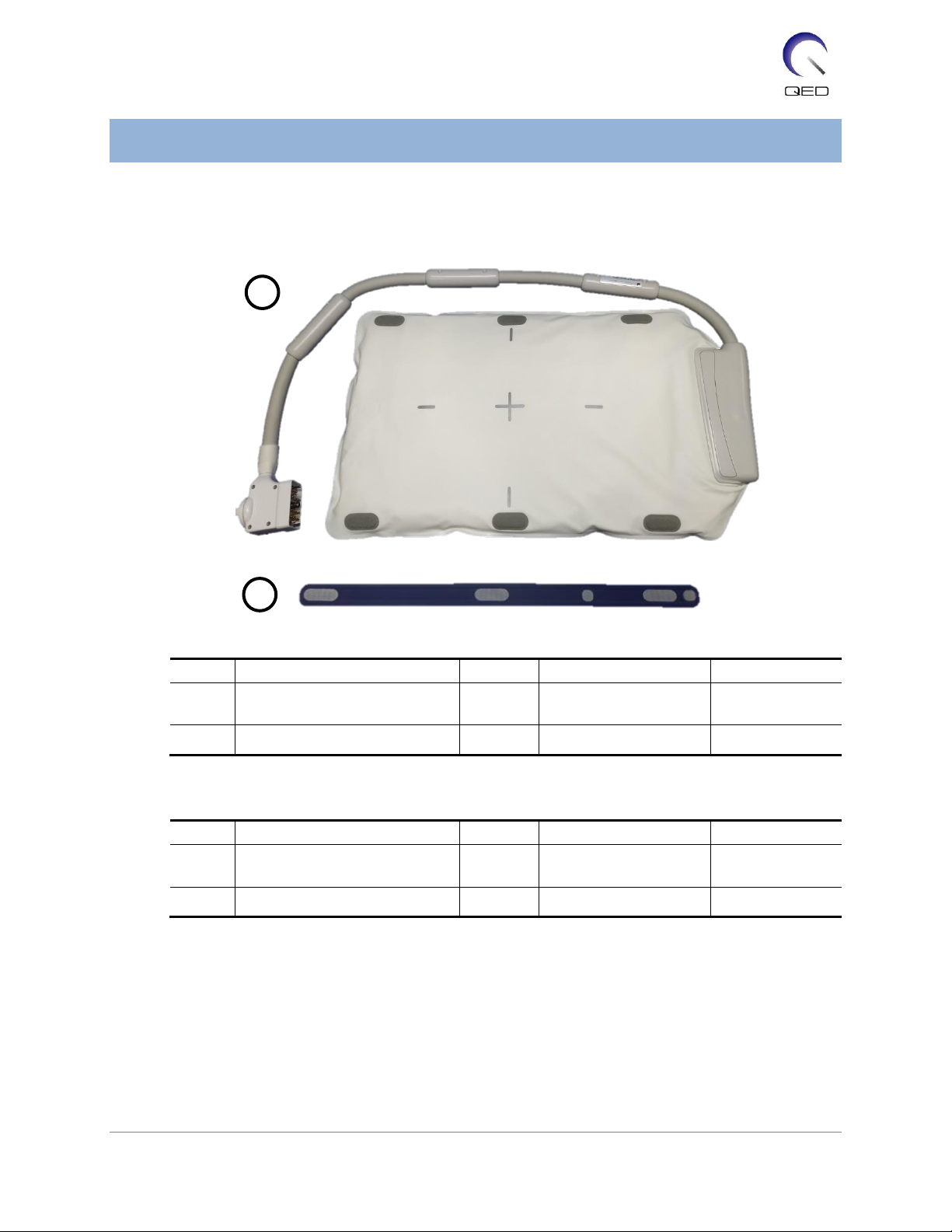
Chapter 2 –Shape Coil Components........................................................................................................6
Chapter 3 –Safety ...................................................................................................................................7
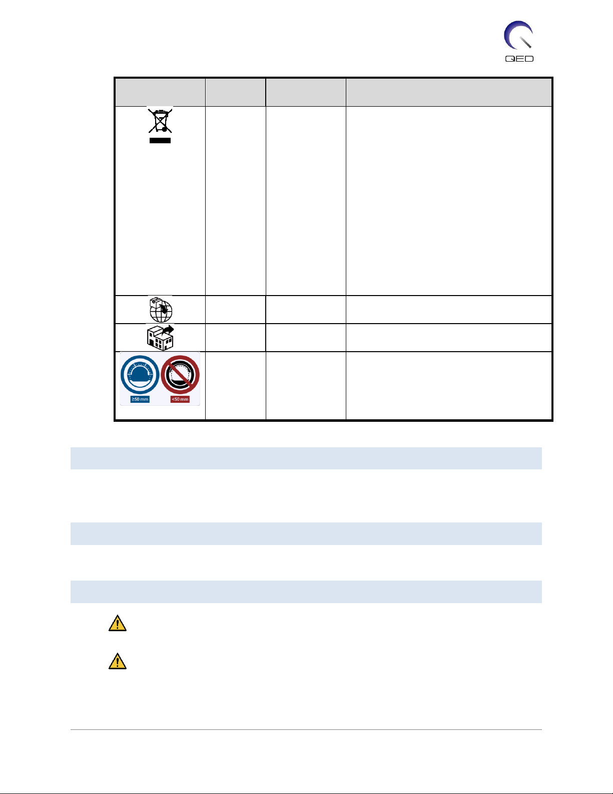
3.1 Symbol Glossary.......................................................................................................................7
3.2 Indications ...............................................................................................................................8
3.3 Contraindications.....................................................................................................................8
3.4 Precautions..............................................................................................................................8
3.5 Cautions –RF Coil.....................................................................................................................9
3.6 Cautions –Shape Coil.............................................................................................................11
3.7 Emergency Procedures...........................................................................................................13
Chapter 4 –Quality Assurance...............................................................................................................14
4.1 Phantom Image Test –1.5T MRI System.................................................................................14
4.2 Phantom Image Test –3.0T MRI System.................................................................................21
Chapter 5 –Coil Setup and Use..............................................................................................................30
5.1 Coil Setup...............................................................................................................................30
5.1.1 Connecting Two Shape Coils...........................................................................................30
5.1.2 Securing the Coil to the Patient (Optional)...................................................................... 32
5.2 Patient Positioning and Scanning............................................................................................ 33
5.2.1 Patient Positioning for Trunk Imaging.............................................................................34
5.2.2 Patient Positioning for Arm Imaging ...............................................................................38
5.2.3 Patient Positioning for Leg Imaging................................................................................. 41
Chapter 6 –Cleaning, Maintenance, Service, and Disposal.....................................................................46
6.1 Cleaning the RF Coil................................................................................................................ 46
6.2 Maintenance.......................................................................................................................... 46
6.3 Service ...................................................................................................................................46
6.4 Disposal ................................................................................................................................. 46
6.5 Expected Service Life..............................................................................................................47
Chapter 7 –Guidance and Manufacturer’s Declaration – Electromagnetic Compatibility (EMC).............48
7.1 Classification..........................................................................................................................48
7.2 Environment and Compatibility..............................................................................................48
7.3 Electromagnetic Emission.......................................................................................................49
7.4 Electromagnetic Immunity .....................................................................................................49

5 | P a g e 6000921 Rev. 1
Chapter 1 – Introduction
1.1 Description
Receive-only RF coils receive magnetic resonance signals generated in hydrogen nuclei (protons)
in the human body. The received signals are amplified and transmitted to the MRI system,
where they are processed into tomographic images by the computer.
The Shape Coil is used to examine general human anatomy, such as torso, pelvis, joints, bones
and extremities.
1.2 Operating Environment and Compatibility
The 1.5T and 3T 16ch Shape Coils are intended to be used in conjunction with the following
Canon MRI Systems in a specialized healthcare facility:
•Vantage Orian 1.5T
•Vantage Fortian 1.5T
•Vantage Galan 3T (STD & XGO)
•Vantage Centurian 3T
1.3 User Profile
Operator –Radiologic technologists, laboratory technologists, physicians.
User training –No special training is required to use this coil. However, Canon Medical Systems
provides a comprehensive training course for MRI systems in order to instruct operators on the
correct use of MRI systems.
1.4 Patient Information
Age, health, condition –No special limitations. Do not use the coil for newborns or infants.
Weight –255kg or less (consult the operation manual for the MRI system, and if the maximum
allowable patient's weight for the system is lower than that for this coil, priority must be given
to the maximum weight for the system).

6 | P a g e 6000921 Rev. 1
Chapter 2 – Shape Coil Components
The Shape Coil is shipped with the parts shown below. Upon receipt, please ensure that all
parts are included in the shipment. Please contact your Canon Medical Systems representative
for replacement or replenishment of any accessories listed here.
Shape Coil Contents
Item #
Description
Quantity
Canon Part #
QED Part #
1
Shape Coil
1
MJAB-207A (1.5T)
MJAB-202A (3.0T)
Q7000198 (1.5T)
Q7000199 (3.0T)
2
Hook-and-Loop Fastener Strap
2
BSM41-8764E
3006899
Shape Coil W Contents
Item #
Description
Quantity
Canon Part #
QED Part #
1
Shape Coil W
2
MJAB-217A (1.5T, W)
MJAB-212A (3.0T, W)
Q7000198 (1.5T)
Q7000199 (3.0T)
2
Hook-and-Loop Fastener Strap
4
BSM41-8764E
3006899
2
1

7 | P a g e 6000921 Rev. 1
Chapter 3 – Safety
This section describes the general precautions and safety information that must be observed
when this coil is used.
CAUTION
Before using the coil, review the safety information in the MRI system operation
manual for a full list of safety considerations.
3.1 Symbol Glossary
Symbol
Number
Standard
Title, Meaning
1641
ISO 7000
IEC 60417
Operator's manual, Consult operating
instructions before operating the device
5172
ISO 7000
IEC 60417
Class II equipment
5333
ISO 7000
IEC 60417
Type BF applied part
3082
ISO 7000
IEC 60417
Manufacturer and Date of Manufacture
6193
ISO 7000
IEC 60417
RF Coil, Receive
5.1.2
ISO 15223-1
Indicates the Authorized Representative in
EU
5.1.2
ISO 15223-1
ISO 20417
Indicates the UK Responsible Person
5.1.2
ISO 15223-1
SwissMedic
Indicates the authorized representative in
Switzerland
2493
ISO 7000
IEC 60417
Catalog Number
2498
ISO 7000
IEC 60417
Serial Number
0632
ISO 7000
IEC 60417
Temperature limit
2620
ISO 7000
IEC 60417
Humidity limitation
2621
ISO 7000
IEC 60417
Atmospheric pressure limitation
5.7.7
ISO 15223-1
Medical Device

8 | P a g e 6000921 Rev. 1
Symbol
Number
Standard
Title, Meaning
N/A
EN50419
EU2012/18/EU
The use of this symbol indicates that this
product should not be treated as
household waste.
By ensuring that this product is disposed of
correctly, you will help prevent potential
negative consequences for the
environment and human health, which
could otherwise be caused by
inappropriate waste handling of this
product.
For more detailed information concerning
the return and recycling of this product,
please consult the supplier from whom you
purchased the product.
5.1.8
ISO 15223-1
Importer
5.1.9
ISO 15223-1
Distributor
N/A
N/A
Separate the RF coil from the gantry inner
wall by at least 50 mm. Burn injuries may
result due to the electric field that is
generated in the RF coil when a high-
frequency magnetic field is transmitted.
3.2 Indications
The Shape Coil is intended for use with Canon 1.5T or 3.0T MR systems to produce diagnostic
images of general human anatomy that can be interpreted by a trained physician.
3.3 Contraindications
None.
3.4 Precautions
Patients with increased likelihood of seizures or claustrophobia may require special
care. Consult the MRI system operation manual.
Patients who are unconscious, heavily sedated, or in a confused mental state are at
increased risk of burn injury because they may not be able to notify the operator of heat
or pain due to excessive heating and tissue damage.

9 | P a g e 6000921 Rev. 1
Patients with an inability to maintain reliable communications (for example, young
children) are at increased risk of burn injury because they may not be able to notify the
operator of heat or pain due to excessive heating and tissue damage.
Patients with loss of feeling in any body part are at increased risk of burn injury because
they may not be able to notify the operator of heat or pain due to excessive heating and
tissue damage.
Patients who have difficulty regulating their body temperature or who are particularly
sensitive to increases in body temperature (for example, patients with fever, cardiac
failure, or impaired perspiration) are at increased risk of burn injury or their body
temperature may increase.
Ensure that the patient does not wear clothing that is wet or dampened by perspiration.
The presence of moisture increases the risk of burn injury.
3.5 Cautions –RF Coil
Do not place any disconnected devices (RF coils, cables, etc.) in the gantry during
scanning. Remove unneeded RF coils from the couchtop and confirm that RF coils in use
are connected to the connector port before scanning.
Disconnected RF coils present during scanning can cause a high-frequency induction
current loop to form, resulting in burn injury to the patient. In addition, devices may be
damaged.
Connect only the designated RF coils to the RF coil connection port.
Do not use a defective RF coil, especially if the outer covering has been damaged or if
metal parts are exposed. There is a risk of electric shock.
Do not attempt to change or modify the coil.
Unauthorized modifications could result in
burn injury, electric shock, or decreased
image quality.
Do not cross or loop coil cables. A high-
frequency current may form and burns may occur.
Ensure that the patient does not come into direct contact with the coil cables. Burn
injuries may result due to the electric field that is generated in the RF coil when a high-
frequency magnetic field is transmitted.
Do not allow the patient to form a loop with any body parts. Use pads to ensure that
the patient’s hands and legs do not touch the coil, MRI system, patient table, or another

10 | P a g e 6000921 Rev. 1
body part that may form a loop. A high-frequency current may form and burns may
occur.
Separate the patient from the gantry inner wall by at least 10 mm using foam pads.
Separate the patient from the RF coil cable by at least 10 mm using foam pads.
Separate the RF coil cable from the gantry inner wall by at least 10 mm using foam pads.
Burn injuries may result due to the electric field that is generated in the RF coil etc.
when a high-frequency magnetic field is transmitted.
Separate the RF coil from the gantry inner wall by at least 50 mm using foam pads. Do
not allow the RF coil to come into contact with the gantry inner wall while imaging.
Damage to the RF coil may occur and/or image quality may be degraded if the RF coil is
within 50 mm of the gantry inner wall during imaging. Foam pads of 50 mm or greater

11 | P a g e 6000921 Rev. 1
thickness when fully compressed that are supplied with the MR system can be used to
ensure suitable spacing when placed between the RF coil and the gantry inner wall.
MR System Pads That Can be used to Separate Shape Coil from Gantry Wall
W300, D80, T20mm pad
W300, D80, T30 mm pad
Confirm that the cable of the coil is on the couchtop before sending the patient into the
gantry. If the couchtop is moved with the cable protruding, the cable may interfere with
the MRI system main unit, which could result in shifting of the coil position or in the
patient being caught and injured by the system.
Stop the scan immediately if the patient complains of warming, tingling, stinging, or
similar sensations. Contact a physician before continuing with the scan.
Ensure that the coil does not come into contact with liquids, such as water or
medications.
The enclosure of the coil and the parts inside the coil may appear in the images under
certain imaging conditions (for example, when a sequence with a short echo time (TE) is
used or when the pixels are large).
If a coil is found to be defective, stop using the coil immediately and contact your Canon
representative.
Use only the accessories described in this manual with the coil.
3.6 Cautions –Shape Coil
Do not use the coil for examining newborns or infants. Heat dispersal will be inhibited if
the coil covers most of the body surface. This would likely cause a rise in body
temperature, possibly resulting in burn injuries.

12 | P a g e 6000921 Rev. 1
Do not route the coil cable along the inner surface of the gantry in the circumferential
direction. Doing so will cause induction current to flow in the cable, resulting in heating
of the cable.
Do not fold the coil by 180near the case of the coil (as shown in the figure below).
Doing so will apply excessive stress to the folded part of the coil, possibly damaging the
coil.
Do not set the coil under the trunk of the patient. Doing so will subject the coil to
excessive stress, possibly damaging the internal circuit of the coil.
When storing the coil, be sure to spread the coil and do not place heavy objects on it.
Doing so will subject the coil to in excessive stress to the coil, possibly damaging internal
circuits.
If metal parts of the coil or printed circuit board are exposed because the outer cover of
the coil is torn or other sections are damaged, immediately stop using the coil. There is
a risk of electric shock.
When two coils are used in combination, use the supplied hook-and-loop fastener strap.
If they are connected without using the supplied hook-and-loop fastener strap, image
quality may be degraded.
Be sure to prevent the hook-and-loop fastener strap from coming into direct contact
with the patient's skin. Scraping the hook surface of the strap against the patient's skin
may result in injury to the patient.
Make sure that there is no possibility of the belt or cable becoming looped or twisted
around the patient's neck. Failure to do so may result in injury or choking of the patient.

13 | P a g e 6000921 Rev. 1
3.7 Emergency Procedures
In case of an emergency during the scan, stop the scan immediately, remove the patient from
the room, and obtain medical assistance, if necessary.
If a serious incident occurs in the EU, it should be reported to the manufacturer and the
Competent Authority of the Member State in which the user facility is established.

14 | P a g e 6000921 Rev. 1
Chapter 4 – Quality Assurance
4.1 Phantom Image Test –1.5T MRI System
Use the following procedure for 1.5T MRI Systems.
Before starting the Quality Assurance test, measure the temperature of the shield room. The
image test can be performed using the automatic SNR measurement tool.
Coil
Phantom
Part number
Shape Coil
10-L copper sulfate phantom 2
BSM41-3176
The procedure for performing the image test without using the automatic SNR measurement
tool is described below.
(1) In this order, place the mat, phantom holder 2 (supplied with the system), and phantoms
on the couchtop as shown in the figure below.
(2) Connect the coil connector to the connector port at the head end of the couchtop.
(3) Position the coil so that the center of the coil is over the border between the two
phantoms. The crosshair marked on the coil main unit indicates the center of the coil.

15 | P a g e 6000921 Rev. 1
(4) Secure the coil to the phantoms using the belt supplied with the system. Place the belt in a
position that is not at the center of the coil so that the center of the coil is visible for
alignment with the positioning projector.
(5) Adjust the position of the coil so that the positioning projector beam is aligned with the
center of the coil and then send the coil to the center of the gantry. Using the couch
operation button, move the couchtop to a position where the couchtop position indicator
on the gantry operating panel reads 200.
(6) Register the patient. Enter 170 cm for the height and 60 kg for the weight.
(7) Select "Typical PAS" →"Coil QA" and click [Other]. Select the following sequences in the
PAS "Other" field.
Sequence name
Required / Not required
FE_slt
Required
FE_map
Required
SNR
Required

16 | P a g e 6000921 Rev. 1
(8) Set the parameters for the sequence as specified below.
FE_slt: Setting change is not required.
(The set value of each parameter is described in the table below.)
Parameter
Set value
Change from default setting
required
FOV
35 35 cm2
Matrix
256 256
No Wrap
(PE) 1.0 / (RO) 1.0
TR
50 ms
NAQ
1
Slice Num.
3
Thick
8 mm
Gap
0 mm
Plane
Other
Encode direction
Other
TE
5 ms
Flip angle
90

17 | P a g e 6000921 Rev. 1
FE_Map: Change the FOV to 35 cm 35 cm.
Other setting changes are not required.
(The set value of each parameter is described in the table below.)
Parameter
Set value
Change from default setting
required
FOV
35 35 cm2
Matrix
64 64
No Wrap
(PE) 1.0 / (RO) 2.0
TR
185 ms
NAQ
1
Slice Num.
20
Thick
6 mm
Gap
6.5 mm
Plane
Axial
Encode direction
RL
TE
4 ms
Flip angle
20
SNR: Change the FOV to 35 cm 35 cm.
Change No Wrap to RO:2.0 / PE:2.0.
Other setting changes are not required.
(The set value of each parameter is described in the table below.)
Parameter
Set value
Change from default setting
required
FOV
35 35 cm2
Matrix
256 256
No Wrap
(PE) 2.0 / (RO) 2.0
TR
200 ms
NAQ
1
Slice Num.
1
Thick
5 mm

18 | P a g e 6000921 Rev. 1
Gap
1 mm
Plane
Axial
Encode direction
RL
TE
15 ms
Flip/Flop
90/180
When the couchtop is moved with phantoms placed on the couchtop, wait
approximately 5 minutes to allow the liquid in the phantoms to stabilize before
starting the image test. If scanning is started before the liquid in the phantoms
stabilizes, the resulting sensitivity nonuniformity in the image causes incorrect
measurement of the SNR.
(9) Start scanning using any of the above sequences. Now, record the RF Level and TGC value
(TGC RFOut ratio:x.xxxxxx ) displayed in the Acquisition window. Record the TCG value that
is displayed after the RF Level. When recording the TGC value and RF level, round three
decimal places to two decimal places. In addition, record the receiver gain that is displayed
in the Acquisition window when the SNR sequence is executed.
(10) Display the intermediate images acquired using the SNR sequence.
NOTE: How to display the intermediate images
1. In the Image Matrix window, select "File" and then "Options".
2. Select the show radio button for "Intermediate" under "Filters" in the Image
Matrix Options window.

19 | P a g e 6000921 Rev. 1
3. The images displayed with an even-numbered scan ID in the Image Matrix
window are intermediate images.
(11) Set the signal ROI and noise ROI as shown in the figure below. Now, record the mean signal
value (mean value) of the signal ROI and the noise variance (Noise SD value) of the noise
ROI in section 1 of the installation quality check sheet.
Signal value (mean value)
ROI size : 25 cm 2 cm
Position AP direction : Center of the phantom
RL direction : Center of the phantom
Noise value (SD value)
ROI size : 20 cm 3 cm

20 | P a g e 6000921 Rev. 1
Position AP direction : Position free from the influence of the flow in the encode
direction in the signal area
(12) Calculate the SNR using the formula below.
SNR calculation
SNR =
(SD)valueNoise
(mean)valueSignal
correction value k
Phantom temperature
Correction value k
18C
0.90
19C
0.92
20C
0.94
21C
0.97
22C
1.00
23C
1.03
24C
1.06
Measure the temperature of the phantom using the thermolabel attached to the
phantom. If the phantom temperature differs from the shield room temperature,
the calculation result using the above formula may not be correct. To avoid this,
place the phantom in the shield room 1 hour before starting image testing so that
the phantom temperature matches the shield room temperature.
This manual suits for next models
5
Table of contents
Popular Industrial Equipment manuals by other brands

Conductix-Wampfler
Conductix-Wampfler R Series Installation, operation & maintenance manual

Schmalz
Schmalz SCPMb operating instructions

ABB
ABB HT562876 Operation manual

Esoteric
Esoteric AB-T1SC1 owner's manual

DAIRY EQUIPMENT
DAIRY EQUIPMENT Bou-Matic 2000V Operator instructions

ESAB
ESAB KHM 2x400 PS instruction manual