Qianjin Electronic OT86-4F User manual

1
OT860-4F
1310nm Optical Transmitter
User’s Manual

2
1. Introduction
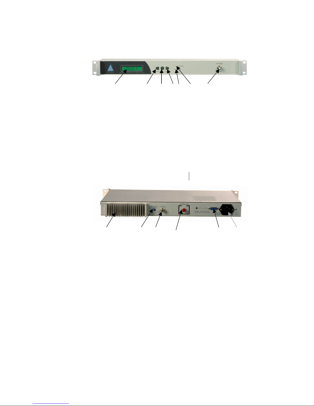
The OT86-4F Optical Transmitter is a new product developed by Shanghai Qianjin
Electronic Equipment Co., Ltd. The Appearance of the chassis features LCD display,
thin film switch, finger-mark-free steel plate, and a vivid color, which make the unit look
elegant and modern. OT86-4F is one intelligent standard 19" 1RU chassis and can be
monitored by the network management software, in this way; the network management
software can get clear status of the set.
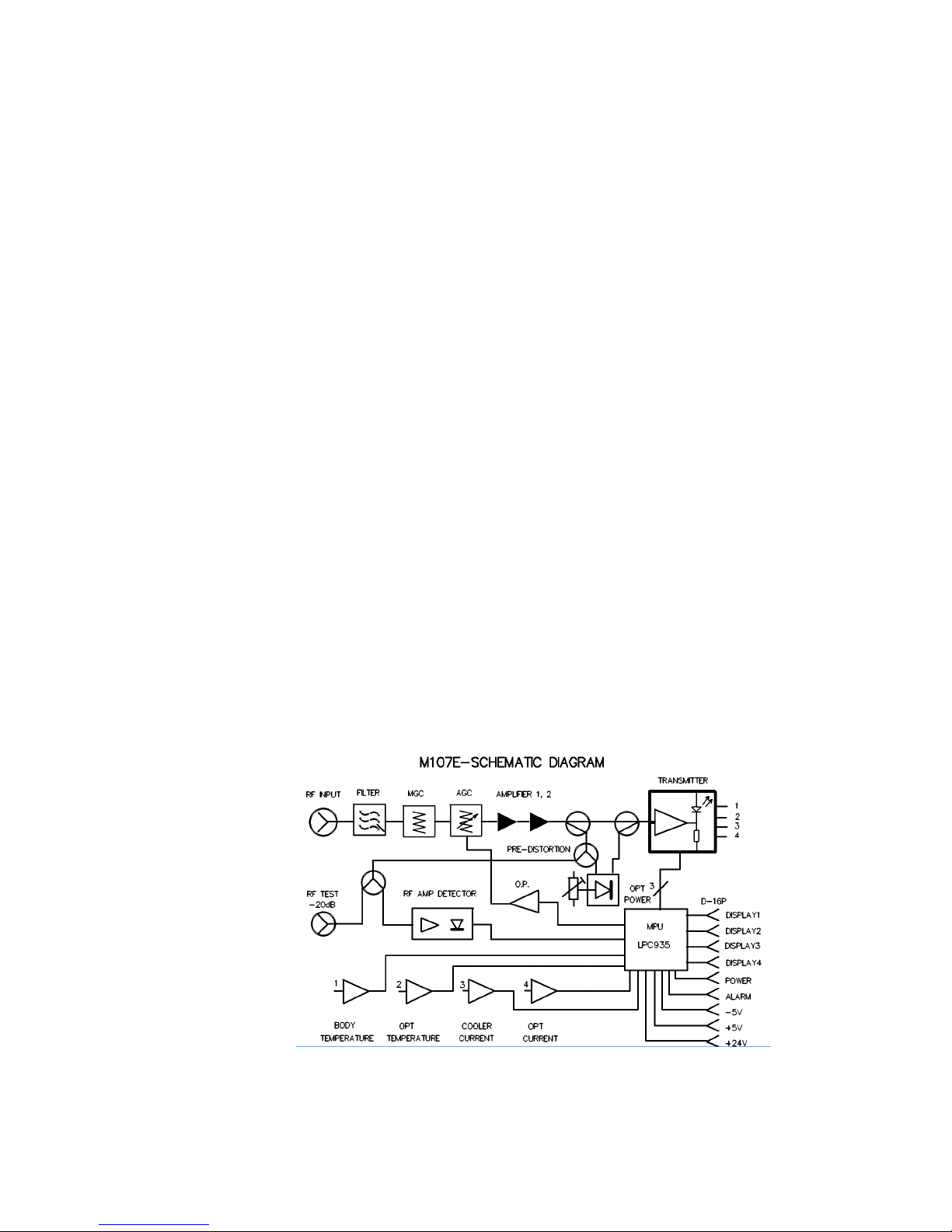
OT86-4F optical transmitter uses an internal isolated FP laser diode. Its high
cost-effective and excellent performance are highlighted by its advanced pre-distortion
correction circuit, RF pre-amplifier circuit, high reliability of the power supply, intelligent
and efficient element management, and unique air- flow design.
2. Features
●
●●
●.
..
.45
55
5~
~~
~870MHz bandwidth;
●
●●
●.
..
.Low noise, low distortion and pre-AMP to meet low RF input signal;
●
●●
● .
..
.Incorporating circuit design built with RF AMP and pre-distortion correction,
enhanced equipment distortion specification;
●
●●
●.
..
.Selective AGC (Automatic Gain Control) of amplitude variable and field MGC (Manual
Gain Control) enables superior link optimization and variable modulation depth (RF
drive level)
●
●●
●.Effective RF overdrive protection for LD (laser diode)alarm and automatic LD
shutdown;
●
●●
●.Effective APC (Automatic Power Control) enable precise optical power levels;
●
●●
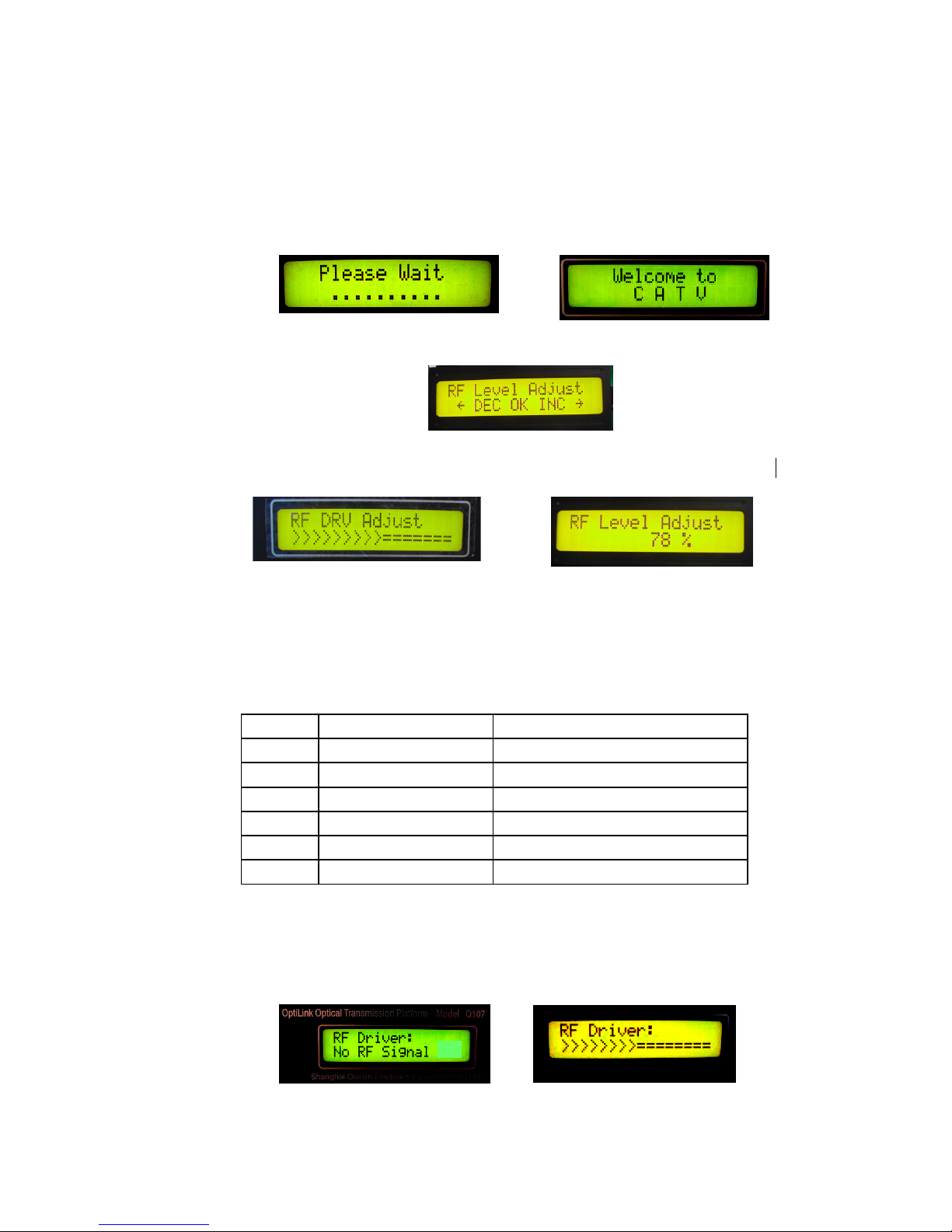
●.LCD display operation state and its information;
●
●●
●. Front panel -20dB RF test port;
●
●●
●.
..
.Alarm for over operation, low optical power output and communication
●
●●
●.
..
.Advanced high efficiency switched power supply to meet the AC voltage wide
fluctuating (176V-264V); redundant switched power supply and automatic alternation;
●
●●
●.
..
.Reliable thermal structure design to ensure high stability and long operating life of
the equipment.
3. OT86-4F Technical Parameters:

3
Parameter
Item
ItemItem
Item
Unit
Unit Unit
Unit
Specification
SpecificationSpecification
Specification
1 Type of laser FP (with optical isolater)
2 Wavelength nm 1310±20
3 Modulation mode Direct Light Intensity Modulation
4 Output Optical Power mW 4 (6dBm)
5 Fiber Connector FC/APC SC/APC
6 Frequency Range MHz 45~860
7 Input RF Signal Level dBµv
15~35
8 AGC range dB 0~10 (MGC: 0~20dB)
9 CNR dB ≥48 note
10
CTB dB ≤-62 note
11
CSO dB ≤-57 note
12
Flatness dB ±0.75
13
RF Input Impedance Ω75
14
RF Input Return Loss dB ≤-15
15
APC Control Precision dB ≤±0.2
16
ATC Control Precision ℃
℃℃
℃25±2
17
Max TEC Operating current mA DC+5V@850
18
MTBF h ≥40.000
19
Laser Operating Voltage Range V DC±4.5--±5.5
20
Laser Operating Temperature Range ℃
℃℃
℃+5~+40
21
Overall Storage Temperature Range ℃
℃℃
℃-25~55
22
Overall Relative Humidity % 40~70
23
Overall Power Supply Input (with Filter) V AC220(176~264V)
24
Power Dissipation W 12
25
Dimensions (WxDxH) mm 480x310x45
26
Weight kg 3
note:(Testing Condition):
Optical Link Loss:10km Fiber + Optical Attenuator
RF Input:59PAL-D/K Channels 47-550MHz,Input Optical Level: –1dBm

4
4. Appearance description (OT86-4F as sample)
①②③④⑤⑥⑦
Front Panel Features
①
①①
①、
、、
、LCD: Display operation states and its information;
②
②②
②、
、、
、Lift Key: Select operation states;
③
③③
③、
、、
、Middle Key: AGC control to adjust the deeps of modulation, when
selected using the lift key and right key to decrease and
increase the deeps of modulation
④
④④
④、
、、
、Right Key: Select information of module
⑤
⑤⑤
⑤、
、、
、Laser LED: Read ~no laser, Green ~laser on;
⑥
⑥⑥
⑥、
、、
、Alarm LED:
::
:Flashing when operation state over usually and
communication;
⑦
⑦⑦
⑦、
、、
、RF test port : -20dB RF level test port.
①②③④⑤⑥
Rear Panel Features
①
①①
①、
、、
、Radiator:
②
②②
②、
、、
、RF Attenuator:
::
:For suitable RF level(see 6.4)
③
③③
③、
、、
、RF input: The RF input level never be bigger then 50dBm
④
④④
④、
、、
、Optical signal output:Interface SC/APC or FC/APC
⑤
⑤⑤
⑤、
、、
、RS232c port(option): Communication with PC
⑥
⑥⑥
⑥、
、、
、Power in: Connection this set to power and Using the fuse
of 250V/1A

5
5. Operations:
5.1. Display Explanations of LCD
a; LCD displays 16 characters a line, totally two lines.
b, Parameter name is in the first line; value is in the second line.
After plugging in to the suitable power socket this set will automatically
delay 7 seconds before opening RF amplifier. Shows as follow:
5.2. Press middle key:
Changing the amplitude of RF driving signal then change the modulation depth
of laser and can using the lift key and right key to decrease and increase it.
Amplitude of RF Amplifier working status
(There is RF signal) (If there is no RF signal)
5.3. Operation Explanations of Left Key:
Press the Lift key, the following information will pop up:
1 Optical Power:Optical output power
Optical output powerOptical output power
Optical output power
2(note1)
RF Driver:Modulation of Laser
Modulation of LaserModulation of Laser
Modulation of Laser
3 OPT Current:Bias current of Laser
Bias current of LaserBias current of Laser
Bias current of Laser
4 OPT Temperature:Temperature of Laser
Temperature of LaserTemperature of Laser
Temperature of Laser
5 Cooler Current:The current of cooler
The current of coolerThe current of cooler
The current of cooler
6 DC +24V Test:Test value of +24V
Test value of +24VTest value of +24V
Test value of +24V
7 DC +5V:Test value of+5V
Test value of+5V Test value of+5V
Test value of+5V
Note1:If no RF signal it will display “no RF signal” as fellow lift finger. Otherwise
LCD will display the amplitude of RF signal as fellow right finger.
Totally 16 words“>”,User may adjusting the RF amplitude by press the lift
Or right key (see 7.4) according to the number of TV channels transmitted
And the parameter of your system to enables superior link optimization and
Variable modulation depth (RF drive level).

6
5.4. Operation Explanations of Right Key::
Press the right key, the following information will pop up:
1(note2)
Module:
OT860-4F
Product model
Option range
2 MANUF Date:Data of leaving factory
3 Module SN:Series Number of Module
4 Laser Type:Series Number of Laser
Note2:This well change as your option
5.5. Connect the mixed RF signal to F port on the rear panel. The input level should
be within a range of 15-35dBmv. On condition that the distortion specification is
guaranteed. This equipment can automatically adjust the RF amplitude with in
8dB, if the RF signal is too big then 35dBm; you can adjust the attenuator on the
rear panel to reduce the RF signal from zero to 20 dB to improve CNR. Local
RF level can be tested from the -20dB port on front panel to get the actual
operating RF value.
6. Caution
6.1. When you get the Transmitter check it, once you find any problem, please
contact the product supplier as soon as possible.
6.2. The transmitter should be properly grounded.
6.3. For it running correctly you must wait for half an hour after turn on
6.4. The fiber FC/APC connector should be cleaned with absolute alcohol, to
minimize the additional loss or reflection caused by dust, which will affect the
specification. Connect the tail fiber to FC/APC socket on the rear panel, and
keep the fiber hanging down.
6.5. If the laser run well the green LED is on and will flash once a second. If it
becoming red means the laser is out of working. The ALARM red LED will flash
if there is any fault in this machine. When the problem is being solved the
transmitter will be operating constantly.
7. Complete List
a. OT86-4F Transmitter one
b. Power-cord one
c. User’s Manual one
Table of contents
Popular Transmitter manuals by other brands

Cockpit
Cockpit CKNPID1 quick start guide

ASTEL
ASTEL TTP 101 operating instructions

Honeywell
Honeywell TCC800MS quick start guide

Dwyer Instruments
Dwyer Instruments PROXIMITY Series Installation and operating instructions

Novus
Novus RHT Climate-WM Series instruction manual

TFA
TFA 30.3157 instruction manual