Qimarox Prorunner 12 User manual

User Manual
Prorunner 12
Version 2.1 - 09/02/2022

About this manual
2
UM Prorunner PR12 v2.1 EN
Qimarox
Nobelstraat 43
3846 CE Harderwijk
The Netherlands
Tel: +31 341 436 700
Fax: +31 341 436 701
E-mail: info@qimarox.com
Internet: www.qimarox.com
Copyright © Qimarox B.V.
All rights reserved. No part of this publication may be reproduced, stored in a computer database or
published in any form or in any way electronically, mechanically, by means of photocopying,
recordings or in any manner without prior written permission from Qimarox.

About this manual
UM Prorunner PR12 v2.1 EN
3
Table of contents
1About this manual 4
Introduction .....................................................................................................................4
Product documentation....................................................................................................4
Source language .............................................................................................................4
Symbols used in the manual............................................................................................5
Terminology list ...............................................................................................................5
Further support and information.......................................................................................5
2General 6
Machine identification......................................................................................................6
Machine layout drawing and specifications ......................................................................6
Warranty .........................................................................................................................7
Liability............................................................................................................................7
CE Declaration of Conformity ..........................................................................................8
3Safety 9
Intended use of the machine ...........................................................................................9
User types and qualifications...........................................................................................9
Safety instructions.........................................................................................................10
Safety provisions...........................................................................................................11
Sound level ...................................................................................................................13
Personal safety .............................................................................................................13
Potential risks................................................................................................................14
Machine end of life and disposal....................................................................................15
4Description 16
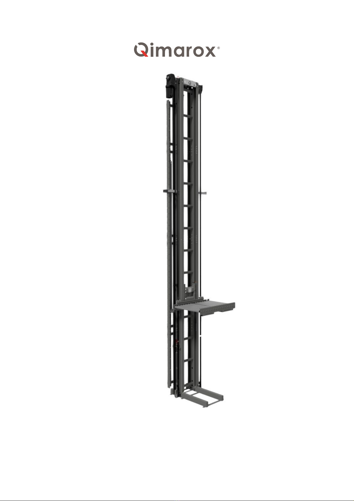
General overview ..........................................................................................................16
Working principle...........................................................................................................17
Sensors.........................................................................................................................18
Motor ............................................................................................................................22
Control ..........................................................................................................................22
Specifications................................................................................................................23
5Installation 24
Delivery.........................................................................................................................24
Possible installations .....................................................................................................24
Unpacking.....................................................................................................................25
Location ........................................................................................................................25
On-site transport ...........................................................................................................25
Preparations for a Qimarox installation (optional)...........................................................26
Installing the machine....................................................................................................26
6Maintenance 33
Specific safety regulations .............................................................................................33
Preventive maintenance ................................................................................................33
Cleaning........................................................................................................................35
Removing the carrier .....................................................................................................36
7Troubleshooting 38
8CE declaration of conformity 40
9Labels 41
10 Electrical drawings 42
Drives ...........................................................................................................................42

About this manual
4
UM Prorunner PR12 v2.1 EN
1 About this manual
Introduction
This manual gives information about the vertical conveyor Prorunner 12. From here on, the
Prorunner 12 is referred to as the 'machine'.
The function of the machine is vertical movement of products or AGV’s within an automated
transport system.
This manual is intended for:
•Retailers/Original Equipment Manufacturers (OEM) project engineers and mechanics.
•Operators, installation and maintenance engineers and other users.
As soon as possible after purchase of the machine, carefully read this manual.
Before you operate the machine, you must read this manual. Make sure that you are familiar
with the content of the manual and the machine.
System integrators/OEMs
This manual explains machine configurations that can be used to set up the machine. It also
provides instructions on how to add or change the machine’s technical components.
Users
The machine may be supplied fully assembled. If so, some chapters in this manual will not be
applicable.
To integrate the machine within a transport system, refer to the documentation provided by the
OEM of the transport system or AGV.
Product documentation
Document
Reference
Machine manual1UM Prorunner PR12 v2.1 EN
Machine layout drawing2Layout drawing Prorunner PR12 XXXXXXX
Electrical drawings1
Electrical drawing Prorunner PR12
Refer to chapter 10
Motor specifications2Gearmotor Prorunner PR12 XXXXXXX
Specification document2Specifications Prorunner PR12 XXXXXXX
Functional description1FD Prorunner PR12 v1.0 EN
OEM parts of the machine Refer to the manufacturer
Source language
This manual was originally written in the English language.
1Generic information
2Machine specific information

About this manual
UM Prorunner PR12 v2.1 EN
5
Symbols used in the manual
The following symbols are used in this manual.
WARNING
Risk of serious injury to the user if the instructions are not accurately
followed.
CAUTION
Risk of damage to the machine if the instructions are not accurately followed.
Note
To provide additional information to the user about a task or issue.
Terminology list
The table below explains common terms used in this manual.
Term Definition
Machine The Prorunner 12
AGV
The Automated Guided Vehicle that can be transported by the
machine
Carrier The component moving the product or AGV up and down
Infeed position The position from which the product or AGV moves on the carrier
Outfeed position The position from which the product or AGV moves off the carrier
Fenced area Area around the machine that unauthorized personnel cannot enter
for safety reasons.
Transport
system
Combination of machines that is used to transport products
Further support and information
Qimarox can supply additional expertise and support services, for:
•Training
•Global support
•Service contracts
For more information please contact Qimarox.

General
6
UM Prorunner PR12 v2.1 EN
2 General
Machine identification
The machine identification is given on the type plate. For the location, refer to Chapter 9.
Refer to the Specifications document of the machine for the specifications and for the
applicable products.
Machine layout drawing and specifications
After a machine order is placed, a Machine layout drawing and Specifications document is
handed over for approval. After approval, the Specifications document is used as a reference
for this manual.
The complete technical documentation of
the machine consists of:
•Machine layout drawing (see
sample)
•Specifications document
•Electrical drawings
•Functional software description of
the software function block
This Machine layout drawing and the
Specifications document include:
•The machine serial number
•Product dimensions and mass
•Machine dimensions
•Machine configuration
•Machine speed and capacity
•Motor specifications
•Electrical components

General
UM Prorunner PR12 v2.1 EN
7
The machine can only be used according to the specifications in this manual, the machine
layout drawing and the specifications document.
If you want to use the machine outside the recommended specifications, you must contact
Qimarox to check if this is possible. Inappropriate and/or modified use of the machine can
result in dangerous safety issues and/or damage. You must obtain written confirmation from
Qimarox before using the machine in a modified or unspecified manner.
Qimarox cannot be held liable for any accidents and/or damages that may occur through
inappropriate unauthorised use of the machine.
Warranty
The scope and duration of the warranty is agreed upon when an order is placed for the
machine. The warranty only applies if the machine is used according to the specifications and
if the user and maintenance instructions are observed. The warranty does not cover wear of
the parts.
The machine warranty is null and void in cases of:
•Unskilled use.
•Inadequate maintenance.
•Unskilled maintenance.
•Modifications made to the machine without prior written permission from Qimarox.
Liability
Qimarox believes to the best of its knowledge that the information in this user manual is
accurate. In the event that technical or typographical errors exist, Qimarox reserves the right
to make changes to subsequent editions of this user manual without prior notice to holders of
this edition. The reader should consult Qimarox if errors are suspected. In no event shall
Qimarox be liable for any damages arising out of or related to this user manual or the
information contained in it. Except as specified herein, Qimarox makes no warranties, express
or implied, and expressly disclaims any warranty of non-infringement, merchantability or
fitness for a particular purpose. Customer’s right to recover damages caused by fault or
negligence on the part of Qimarox shall be limited to the amount paid to Qimarox by the
customer. Qimarox shall not be liable for damages resulting from loss of data, profits, use of
products, or incidental or consequential damages, even if advised of the possibility thereof.
This limitation of liability of Qimarox will apply regardless of the form of action, whether in
contract or tort, including negligence. Any action against Qimarox must be brought within one
(1) year after that cause of action accrues. Qimarox is not liable for damages, accidents,
unsafe conditions, defects, malfunctions, or service failures caused by the following:
•Owner’s or user’s failure to follow Qimarox’s installation, operation and maintenance
instructions, including but not limited to neglecting warnings or regulations as shown
on the machine or in this manual.
•Usage of the machine for other applications, or under other circumstances than
indicated in this user manual. This includes abuse, misuse or negligent acts.
•Modifications of any kind to the machine. This includes the replacement of parts with
parts that are not specified in this manual.
•Insufficient or improper maintenance.

General
8
UM Prorunner PR12 v2.1 EN
CE Declaration of Conformity
The CE declaration can be found in the User manual of the complete system. This manual is
provided by the system integrator.

Safety
UM Prorunner PR12 v2.1 EN
9
3 Safety
Intended use of the machine
The machine is exclusively intended for automated vertical transportation of products or
AGV’s, as described in this manual. For a detailed description of the specifications of use,
refer to section 4.
AGV’s must always drive on and off the machine on their own, without requiring physical
access by persons. Products must always be transported on and off the machine with
automated transport, either by AGV or by conveyor. Manual placement is not allowed.
WARNING
Any other use of the machine is strictly forbidden.
WARNING
Moving persons or standing on the carrier of the machine is strictly
forbidden.
User types and qualifications
The following user types are referred to in this manual:
•The operator
•The mechanical installer
•The electrical installer
•The maintenance engineer
The maintenance engineer must be familiar with the full content of this manual.
Before any person operates, sets up, electrically installs or maintains the machine, permission
to carry out these tasks must be obtained from Qimarox. Qimarox determines if the person is
qualified for carrying out the given task. The machine should only be operated by qualified
personnel.
An electrical installer is only qualified if a person has attended appropriate training and/or
attained appropriate industry standard recognized qualifications. Qimarox can provide training
if required.
Qimarox can also give advice about actions and tasks to be carried out on the machine.

Safety
10
UM Prorunner PR12 v2.1 EN
Safety instructions
General
•Comply with the safety regulations given in this manual. Deviation from these regulations
can lead to unacceptable risks.
•Never close doors (if present) in the fenced area of the machine, when a person is inside
this area.
•Switch off the machine and secure the main power supply switch in the off position with a
padlock to prevent the machine from being switched on while personnel is working within
the fenced area.
•Place the safety locking pin of the carrier in safe position before entering the area under
the carrier.
•Comply with all relevant local legislation and regulations
Set up
•Connect the machine in accordance with the local laws and regulations concerning health
and safety.
•Before putting the machine into use, check if the machine has been set up in accordance
with the instructions in this manual and with the layout drawing.
•Make sure that the transport system complies with all relevant health and safety directives
and regulations.
Starting the machine
•Do not switch the main power supply on when persons are in contact with the machine.
•Do not start the machine when persons are in contact with the machine.
•Do not start the machine when persons are present in the fenced area of the machine.
•Before the machine is put into operation, all machine parts must comply with all relevant
health and safety directives and regulations.
During machine operation
•Keep your hands and feet away from danger zones.
•Make sure you do not wear loose clothing and secure long or loose hair.
•Make sure that no persons or objects are within the range of any moving parts of the
machine.
•Make sure that users know and observe all safety rules with regard to the machine and
the environment in which it operates.
Maintenance and repair
•Turn off the power supply to the machine with the main power supply switch before
starting any maintenance or repair tasks. Secure the main power supply switch in the off
position with a padlock.
•Place the safety locking pin of the carrier in safe position before entering the area under
the carrier.
•Working on lifting devices or on the lifting drive may be started only if the lift is prevented
from unintentional movement or falling.
•Replace damaged or defective parts before putting the machine back into operation.

Safety
UM Prorunner PR12 v2.1 EN
11
•Changes and modifications that may affect the safety of the machine can only be carried
out when these changes and modifications comply with the relevant regulations,
legislation, directives and recognized industry standards.
•If changes and modifications are outside the scope of specifications given by Qimarox in
this manual and Qimarox has not granted permission changes and modifications, then the
changes and modifications will entirely be the responsibility of those persons responsible
for carrying out the changes and modifications.
•Electrical installation tasks must only be carried out by qualified personnel.
Safety provisions
Safety equipment
•Do not disassemble, bypass or disable any safety equipment on the machine.
•Do not start the machine if even a single item of the machine safety equipment is
defective.
•Immediately take the machine out of operation if a single item of the machine safety
equipment is defective.
•Always replace all safety equipment that have been removed from the machine when all
maintenance tasks are complete
The machine has been equipped with the following safety equipment:
•Labels
•Safety locking pin
Note
Replace labels on the machine if they become unreadable or damaged.
For safety reasons, Qimarox requires a fenced area around the machine. Any access doors
must be secured with (interlock) door switches. The (interlock) door switches must be included
in the emergency stop and safety circuit. For information about how to set up the fenced area,
refer to section 3.4.2
The machine is equipped with a safety locking pin which protects the carrier from falling down
during maintenance or inspection. The safety locking pin is located on the side of the machine
and must be manually rotated horizontal. After placing the locking pin, slowly lower the carrier
until it rests on the pin. This pin is installed for personnel safety and cannot be used as fall
protection during operation.
In case of non-compliance with the required safety measures, the CE Declaration of
Conformity will become null and void.
Safety fence
The fenced area must comply with EN ISO 13857 and EN 619 standards.
Make sure that the fence, the fenced area and safety control system comply with local safety
laws and safety rules.
The infeed and outfeed openings of the machine must prevent persons from entering the
danger zone when the machine may cause a danger to a person in that area. Every infeed
and outfeed opening must be fitted with a safety device (door with a safety switch, light

Safety
12
UM Prorunner PR12 v2.1 EN
curtain, etc.) that is embedded in the safety control system, to control the access. All machines
in the fenced off area must stop if the safety control system is triggered due to unsafe access.
If Qimarox supplies the safety fencing, a layout drawing of the safety fencing will be provided.
WARNING
If the carrier moves the through a floor to another level, apply safety
measures to all levels.
Safety controls
The provisions must be designed according to a so-called Performance Level (PL)
corresponding with the current standard for safety functions of a machine or a machine control
in compliance with EN ISO 13849-1:2008. To the machine a PL d applies, in which d indicates
that the risk must be substantially reduced.
Emergency stop circuit
The machine must have an emergency stop circuit. When one of the emergency stop buttons
is pressed, the main power and the control current of the machine are switched off
immediately.
Temperature measuring
For motors that are frequently started and stopped, intermittently operated, use a high
switching frequency or power controller, it is essential to use a motor protection relay and
thermistor protection. This is to avoid prematurely switching the motor protection relay or
overheating of the motor winding in these operational conditions.
Check of the transport time slot
The software should monitor the position of the AGV in the machine during infeed, internal
transport and outfeed. When the related time slots are exceeded, the machine must
immediately stop to avoid damage.
Safety pin
On the side of the column, one safety pin per carrier is mounted. Before entering the area
under the carrier, always place the corresponding safety pin in the horizontal ‘safe’ position.
This can be done by rotating while lifting the pin.
Before restarting the machine, make sure both pins are in ‘up’ position.
Safety pin in ‘safe’ position
Safety pin in ‘up’ position
WARNING
Place the safety pin in horizontal ‘safe’ position before entering the area
under the carrier.

Safety
UM Prorunner PR12 v2.1 EN
13
Sound level
The A-weighted emission sound pressure level at workstations does not exceed 70dB(A).
Note
The sound pressure level applies to typical products and AGV’s. Different
products or AGV’s can increase the sound level.
Personal safety
For your own safety use personal protective equipment.
Always wear proper personal protective equipment when working with, on or near the
machine.

Safety
14
UM Prorunner PR12 v2.1 EN
The following table gives an overview of the required personal protective equipment.
Safety
sign
Protective device
(example) Description When required
Safety helmet
During installation and
maintenance
Protective goggles
During maintenance,
cleaning
Hearing protection
During production
Protective gloves (no
leather, but rubber or
silicone!).
During cleaning
Protective shoes
During installation,
production, maintenance,
cleaning and with slippery
floors
Protective clothing
During cleaning
Safety harness/belt
During installation and
maintenance
Take off your personal protective equipment during a work break to prevent possible residue
from getting onto canteen tables and in your food.
Potential risks
The machine is intended to be integrated into a transport system. Qimarox has attempted to
protect against as many hazards as possible.
The following potential risks should be addressed before machine and assembled parts are
put into operation:
•Risk of injury caused by rotating pulleys
•Risk of injury caused moving belts
•Risk of injury caused by falling products or AGV
•Risk of injury as a result of carrier
•Hazards occurring at places where the machine connects to other parts of the
installation.
The interior of the machine can be accessed through the front and back of the machine.
Protective measures must be applied on each floor level.

Safety
UM Prorunner PR12 v2.1 EN
15
Machine end of life and disposal
Proper use and maintenance of the machine will not involve any environmental risks. When
the machine is no longer useable, the machine should be dismantled and disposed of in an
environmentally responsible manner.
WARNING
Observe all relevant legislation, regulations, instructions and precautions
with regard to health and safety when dismantling the machine.
Observe all relevant legislation, regulations, instructions and precautions
with regard to the disposal of products in the environment.

Description
16
UM Prorunner PR12 v2.1 EN
4 Description
The machine is designed to transport products or AGV’s vertically from one level to another.
The machine must be installed as part of a larger transport system in which the products or
AGV’s are automatically moved on and off the machine.
General overview
The machine consists of a column (A) on
which a gearmotor (B) is mounted. The
gearmotor connects to two belts (C) on
which the carrier (D) is suspended. The
carrier moves up and down through the
column of the machine.
The figure only highligts one set of
components. The carrier, belts and
gearmotor can be duplicated on the other
side of the column, resulting in two
independently moving carriers supported
by a single column.
C
B
A
D

Description
UM Prorunner PR12 v2.1 EN
17
Working principle
Reference procedure
Before starting the machine make sure the machine is empty. When starting the machine, a
reference procedure is needed. During this procedure the carrier moves down to the reference
sensor. When this sensor detects the carrier, the resolver value is set and the machine is
ready to run.
Note
If the machine contains two carriers, both sides of the machine need to reference
separately.
CAUTION
After a loss of power or malfunction of any kind and the drive loses its reference,
the reference procedure needs to be repeated.
Reference sensor

Description
18
UM Prorunner PR12 v2.1 EN
Permission for movement
Once the reference procedure is completed and stopping levels are programmed, the machine
is ready to receive an product or AGV. Once the carrier is in position the product or AGV can
move onto the platform. The product or AGV needs to be completely on the platform and
preferably with its centre of gravity in the centre on the platform. Once in position, the machine
can move the carrier to the desired level. When the carrier is on the desired level, the product
or AGV can move out from the carrier. When the product or AGV are moved completely off the
carrier, the carrier can move to another level.
Note
Communication between AGV and machine is provided by the system integrator
because it is depended on the transport system the machine operates in.
CAUTION
Moving the carrier with a product or AGV protruding will cause damage to the
machine, product, AGV and/or surroundings.
Sensors
This chapter describes the sensors installed on the machine. Note that a unit with a single
carrier only contains the sensors starting with BCA or TCA.
Bottom of the machine
Top of the machine
Reference sensors (BCA-B1 & BCB-B1)
The reference sensors detect the carrier in the reference procedure and set the resolver value.
Bottom limit switches (BCA-S1 & BCB-S1)
The bottom limit switches prevent the carrier from moving out of its allowed range. When one
of these limit switches is triggered, the machine must stop.
Make sure that the limit switches give a signal when the lever is in the horizontal position.
TCB-S1
TCB-E1
TCA-S1
TCA-E1
BCA-B1
BCB-B1
BCB-S1
BCA-S1

Description
UM Prorunner PR12 v2.1 EN
19
Top limit switches (TCA-S1 & TCB-S1)
The top limit switches prevent the carrier from moving out of its allowed range. When one of
these limit switches is triggered, the machine must stop.
Make sure that the limit switches give a signal when the lever is in the horizontal position.
Resolver (TCA-E1 & TCB-E2)
The signals from the resolver allows the frequency inverter to calculate the position of the
carrier. The resolver also monitors the gear motor. In case the frequency inverter notices a
mismatch between de resolver value and the expected value it stops the machine.
CAUTION
Disabling the monitoring of the resolver will result in damage of the machine
and/or surroundings.
Note
For more detailed information about the settings, features and safety provisions,
refer to the functional description.
Locking pin (TCA-B2 & TCB-B2)
The locking pin sensors monitor the
position of the locking pin. When the sensor
is not covered, the pin in in ‘safe’ position.
Do not move the carrier downwards.
WARNING
Moving the carrier downwards when the locking pin sensor is not covered
will result in damage to the machine.
Contour sensors
The machine is fitted with two sensors on each carrier to monitor the contour. If either of the
sensors is covered an object is protruding and the carrier may not move. Alternatively, the
machine can be fitted with thru-beam sensors column (AGV application only).
WARNING
Moving the carrier downwards when one of the contour sensors is
covered with result in damage to the machine or surroundings.
BCA-B2
BCB-B2

Description
20
UM Prorunner PR12 v2.1 EN
Contour of carrier
On the edges of the platform or carrier a
photoelectric sensor with reflector monitors
the transition from carrier to surroundings. If
one of the sensors is covered an object is
protruding and the carrier may not move.
Top to bottom thru-beam (on request)
The corners of each carrier are monitored by 4 thru-
beam contour sensors.
When one of the sensors is covered, do not move the
corresponding carrier. The sensors can be covered by
an product or AGV entering the carrier, or an object
protruding into the path of the carrier.
C1
C2
C3
C4
C1.1
C2.1
C4.1
C3.1
Table of contents
Other Qimarox Accessories manuals