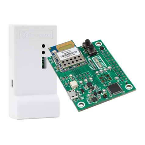
Qorvo QM33120WDK1 User manual

-
QM33120WDK1
USER GUIDE
QM33120WDK1 UG Rev. A, July 2022
Subject to change without notice | All rights reserved
1 of 11
www.qorvo.com
®
Product Overview
The Qorvo® QM33120WDK1 is a development kit for the low
power low cost QM33110W and QM33120W UWB transceivers.
This kit can be used to evaluate the hardware performance of
the devices in TWR, TDoA and AoA systems and can help to
build an evaluation real time location system (RTLS).
It also enables the development of applications based on
DW3110, DW3120, DW3210, DW3220 UWB transceivers.
It includes two different daughter boards (AoA and non-AoA)
mounted on two Nordic nRF52840 DK evaluation boards.
Application firmware development is facilitated by the features
of the Nordic boards such as on-board J-Link debugger, USB
and Bluetooth® Low Energy interfaces.
The QM33120WDK1 is designed to develop applications
compatible with PHY and MAC FiRa specifications.
QM33120WEVB Block Diagram
Key Features
•Convenient kit for evaluation of QM331x0W transceivers
•Daughter boards compatible with Nordic nRF52840 DK
•Provided with UWB CH5/CH9 dual and single antennas
•Access to all QM331x0W GPIOs and interfaces
•Headers on power traces to measure transceiver currents
•Software development with free to use IDE and debugger
•nRF52840 DK evaluation board with:
- nRF52840 Soc with Bluetooth 5.3
- USB interface
- Integrated BLE antenna
- J-Link on-board for debugging and flashing via USB
•Supports UWB RF bands 5 (6.5 GHz) and 9 (8 GHz)
•IEEE 802.15.4-2020 and IEEE 802.15.4z-2020 BPRF
compliant
•Allow development of FiRA compatible applications
•Works with Apple Nearby Interaction software
•Software suite compliant with FiRa PHY/MAC specification
Applications
•Development of point-to-point applications including tag and
anchor
•Software provided for low power TWR and AoA based
systems
•Supports Apple Nearby Interactions applications

QM33120WDK1 UG Rev. A, July 2022
Subject to change without notice | All rights reserved
2 of 11
www.qorvo.com
QM33120WDK1
USER GUIDE
®
1 Overview
The QM33120WDK1 kit content is listed in the following table:
Item
Quantity
Description
QM33120WEVB
1
Daughter board with QM33120W UWB transceiver
Node of AoA system –can measure angular position and distance
(Arduino Shield format)
QM33110WEVB
1
Daughter board with QM33110W UWB transceiver
Tag of AoA system –can measure distance
(Arduino Shield format)
Nordic nRF52840 DK
2
Development board for nRF52840 SoC (Cortex M4 with BLE support)
JL359
1
Directional dual antenna designed for channel 5 and 9 AoA applications
JL159
1
Omnidirectional single antenna designed for channel 5 and 9
Recommended for a tag in AoA applications
Micro USB cables
(Micro B to Type-A)
2
USB cable to connect nRF52840 DK board to a PC
Plastic stand
2
Keeps the nRF52840 DK board in a vertical position
Standoff
6
Allows to fix the nRF52840 DK board on the plastic stand
Table 1 : Kit Content
Note that none of these parts can be ordered separately. They will only be sold as kits.
QM331x0WEVB board and nRF52840 DK board are shipped connected.
Screw the antennas on each QM331x0WEVB board paying attention to the antenna orientation. It is recommended to use a 1 N*m
torque wrench to attach the antenna to the QM331x0WEVB boards, for example HUBER+SUHNER 74_Z-0-0-21.
Attach the nRF52840 DK boards to their plastic stands using the included standoff.
Connect both nRF52840 boards to a PC using the included USB cable and refer to the section QorvoOne GUI.
Figure 1 : Kit Assembly

QM33120WDK1 UG Rev. A, July 2022
Subject to change without notice | All rights reserved
3 of 11
www.qorvo.com
QM33120WDK1
USER GUIDE
®
2 Nordic nRF52840 DK configuration
Figure 2 : nRF52840 DK configuration
J-LINK OB (On-Board Debug Probe) is an integrated programming and debugging tool and should be connected to the Host used to
program or debug the nRF52840 firmware with Segger J-Link and Segger Embedded Studio software.
Figure 3 : J-Link OB
For normal operation, the Host should be connected to nRF52840 SOC through the nRF52840 USB connector.

QM33120WDK1 UG Rev. A, July 2022
Subject to change without notice | All rights reserved
4 of 11
www.qorvo.com
QM33120WDK1
USER GUIDE
®
3 Firmware update
The nRF52840 DK boards are shipped preprogramed. However, to ensure you are using the latest firmware, please check the Qorvo
website for any updates.
Download Segger J-Link software from this web page: https://www.segger.com/downloads/jlink/
Install the J-Link package to your PC.
Connect the J-Link OB USB connector of the nRF52840 DK boards (see previoussection) to thePC and run Segger J-Flash Lite software.
Click on “…” button. Select the target device (nRF52840_xxAA) and click on OK button.
Select the file to download (*.hex) in the nRF52840 flash memory and then click on “Program Device” button.

QM33120WDK1 UG Rev. A, July 2022
Subject to change without notice | All rights reserved
5 of 11
www.qorvo.com
QM33120WDK1
USER GUIDE
®
4 QM331x0WEVB Power Options
QM331x0W transceiver can be powered by DC/DC or LDO.
Using DC/DC improves the power efficiency while LDO reduces the power supply noise.
By default, the transceiver is powered by DC/DC.
Nbr
Name
Default position
Description
J1
VDD1
Closed
Can be used to measure VDD1 current
J2
VDD2
Closed
Can be used to measure VDD2 current
J3
VDD3
Closed
Can be used to measure VDD3 current
J11
VDD2 source
DC/DC
Source of VDD2 power rail –VDD2 can be powered by a 2.5V DC/DC or a 2.5V LDO
J13
VDD3 source
DC/DC
Source of VDD3 power rail –VDD3 can be powered by a 1.6V DC/DC or a 1.6V LDO
J15
VDD1 source
INT
Source of VDD1 power rail –VDD1 can be powered by a 3.3V LDO or by nRF52840 DK board
Table 2 : QM331x0WEVB Power Options
5 QM331x0WEVB Solder Bridge Jumpers
The following table lists the solder bridge jumpers of the QM331x0WEVB.
Solder Bridge
Default State
Description
R3
Open
Connect the TCXO output to QM331x0W oscillator input –When closed, R4 & R5 must be removed
R4
Closed
Connect the quartz crystal to QM331x0W oscillator input –When closed, R3 must be removed
R5
Closed
Connect the quartz crystal to QM331x0W oscillator output –When closed, R3 must be removed
R9
Closed
Connect EN signals of VDD2 DC/DC and LDO to the input power supply –Remove R13 when R9 is closed
R13
Open
When closed, EN signals of VDD2 DC/DC and LDO are driven by EXTON –Remove R9 when R13 is closed
R14
Closed
Connect EN signals of the TCXO LDO to the input power supply –Remove R15 when R14 is closed
R15
Open
When closed, EN signal of TCXO LDO is driven by a GPIO of nRF52840 DK –Remove R14 when R15 is closed
R19
Closed
Connect EN signals of VDD3 DC/DC and LDO to the input power supply –Remove R23 when R19 is closed
R23
Open
When closed, EN signals of VDD3 DC/DC and LDO are driven by EXTON –Remove R19 when R23 is closed
J17
Open
Close it to power the LDO that provides power supply to the TCXO
J21
Open
Do not close –used to make the QM331X0WEVB compatible with a former microcontroller DK
J22
Closed
Do not open –required to make QM331X0WEVB compatible with nRF52840 DK
J23
Closed
Do not open –required to make QM331X0WEVB compatible with nRF52840 DK
J24
Closed
Do not open –required to make QM331X0WEVB compatible with nRF52840 DK
J25
Open
Do not close –used to make the QM331X0WEVB compatible with a former microcontroller DK
J26
Closed
Do not open –required to make QM331X0WEVB compatible with nRF52840 DK
J32
Closed
Do not open –required to make QM331X0WEVB compatible with nRF52840 DK
J33
Closed
Do not open –required to make QM331X0WEVB compatible with nRF52840 DK
Table 3 : Solder bridges and their purposes
They are mainly used:
•to connect either a Crystal Quartz or a TCXO to the QM331x0W transceiver (see figure below)
•to keep the compatibility of QM331x0EVB daughter board with a former microcontroller evaluation board

QM33120WDK1 UG Rev. A, July 2022
Subject to change without notice | All rights reserved
6 of 11
www.qorvo.com
QM33120WDK1
USER GUIDE
®
TCXO
R4
R5
R3
XTI
XTO
QM331x 0W
LDO
J17
VDD _nRF52840 DK
Figure 4 : QM331x0W Clock Tree
6 QM331x0W GPIOs
The following table lists the connections between the QM331x0W GPIOs and the nRF52840 GPIOs.
QM331x0W GPIO
nRF52840 GPIO
GPIO 0
P1.04
GPIO 1
P10.6
GPIO 2 / RXLED
P1.07
GPIO 3 / TXLED
P1.05
GPIO 4
P0.28
GPIO 5
P0.04
GPIO 6
P0.03
GPIO 7 / SYNC
P0.29
GPIO 8 / IRQ
P1.10
Table 4 : Correlation between QM331x0W GPIO and nRF52840 GPIO

QM33120WDK1 UG Rev. A, July 2022
Subject to change without notice | All rights reserved
7 of 11
www.qorvo.com
QM33120WDK1
USER GUIDE
®
7 QorvoOne GUI
The nRF52840 DK boards are shipped preprogrammed. So, you can connect the two nRF52840 DK boards to the PC using the supplied
USB cable. Make sure that the antennas face each other during the evaluation.
Figure 5 : AoA System Evaluation Setup
Install QorvoOne GUI software included in QM33_QorvoOne_DK package and start the application.
The boards will be detected and displayed on the main screen.
For AoA evaluation, ensure that the QM33120WEVB (the one with the dual antenna) is configured as initiator.
Refer to the QM33120WDK1 Quick Start Guide for further information.

QM33120WDK1 UG Rev. A, July 2022
Subject to change without notice | All rights reserved
11 of 11
www.qorvo.com
QM33120WDK1
USER GUIDE
®
Revision History
Revision
Description
A
Initial release
Note: J-Link, J-Link OB, J-Flash Lite, Embedded Studio are registered trademarks of SEGGER Microcontroller GmbH.
Contact Information
For the latest specifications, additional product information, worldwide sales and distribution locations:
Web: www.qorvo.com
Tel: 1-844-890-8163
Email: [email protected]
Important Notice
The information contained in this document and any associated documents (“Product Brief Information”) is believed to be reliable; however, Qorvo makes no warranties
regarding the Product Brief Information and assumes no responsibility or liability whatsoever for the use of said information. All Product Brief Information is subject to change
without notice. Customers should obtain and verify the latest relevant Product Brief Information before placing orders for Qorvo® products. Product Brief Information or the use
thereof does not grant, explicitly, implicitly or otherwise any rights or licenses to any third party with respect to patents or any other intellectual property whether with regard to
such Product Brief Information itself or anything described by such information.
THIS INFORMATION DOES NOT CONSTITUTE A WARRANTY WITH RESPECT TO THE PRODUCTS DESCRIBED HEREIN, AND QORVO HEREBY DISCLAIMS ANY
AND ALL WARRANTIES WITH RESPECT TO SUCH PRODUCTS WHETHER EXPRESS OR IMPLIED BY LAW, COURSE OF DEALING, COURSE OF PERFORMANCE,
USAGE OF TRADE OR OTHERWISE, INCLUDING THE IMPLIED WARRANTIES OF MERCHANTABILITY AND FITNESS FOR A PARTICULAR PURPOSE. Without limiting
the generality of the foregoing, Qorvo® products are not warranted or authorized for use as critical components in medical, life-saving, or life-sustaining applications, or other
applications where a failure would reasonably be expected to cause severe personal injury or death. Applications described in the Product Brief Information are for illustrative
purposes only. Customers are responsible for validating that a particular product described in the Product Brief Information is suitable for use in a particular application.
© 2021 Qorvo US, Inc. All rights reserved. This document is subject to copyright laws in various jurisdictions worldwide and may not be reproduced or distributed, in whole or
in part, without the express written consent of Qorvo US, Inc. | QORVO® is a registered trademark of Qorvo US, Inc.
Other manuals for QM33120WDK1
1
Table of contents
Other Qorvo Microcontroller manuals
Popular Microcontroller manuals by other brands

Renesas
Renesas DA1459 PRO Devkit Series user manual

Renesas
Renesas RL78/I1C user manual

National Instruments
National Instruments AMUX-64T installation guide

NXP Semiconductors
NXP Semiconductors QN9090-DK006 user guide

Silicon Laboratories
Silicon Laboratories Si4010 Series user guide

Murphy
Murphy MURPHYMATIC ASM150 Installation and operation instruction