Figures
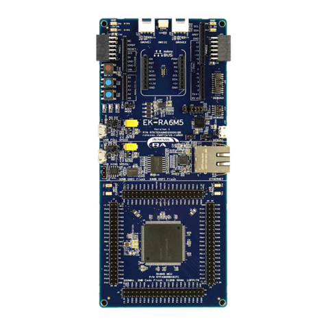
Figure 1. DA1459x PRO Devkit with PRO-MB and the PRO-DB.......................................................... 6
Figure 2. System block diagram............................................................................................................ 7
Figure 3. DA1459x PRO Devkit components........................................................................................ 8
Figure 4: Default hardware setup of DA1459x PRO-Devkit with PMM2............................................... 9
Figure 5. System block diagram of DA14592 PRO-DB (32 KHz only on FCQFN52)......................... 12
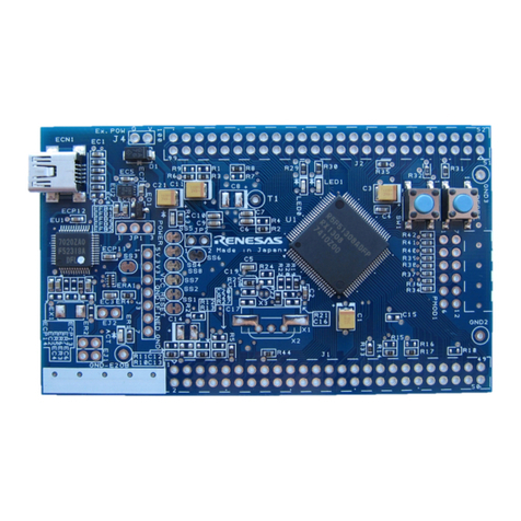
Figure 6. TOP side, WLCSP39 PRO-DB (left), FCQFN52 PRO-DB (right)........................................12
Figure 7. BOTTOM side, WLCSP39 PRO-DB (left), FCQFN52 PRO-DB (right)................................ 13
Figure 8. DA14592 Interface header of WLCSP39 to DA1459x PRO-Motherboard .......................... 14
Figure 9. DA1459x Interface header of FCQFN52 to DA1459x PRO-Motherboard...........................15
Figure 10. The debugging header, J4 .................................................................................................17
Figure 11. The External QSPI memory, (U2) place holder ................................................................. 18
Figure 12. External Memory placeholder and the components .......................................................... 18
Figure 13. Red LED (D1) circuitry ....................................................................................................... 19
Figure 14. Reset circuitry on PRO-Daughterboard .............................................................................19
Figure 15. DA14592 SoC, power pins................................................................................................. 20
Figure 16. SW1 (left), available battery sockets on the bottom side of the daughterboards (right)....20
Figure 17. RF section of DA14592 PRO-DB.......................................................................................21
Figure 18. DA1459x PRO-Motherboard block diagram ...................................................................... 22
Figure 19. DA1459x PRO-Motherboard, 469-16-x.............................................................................. 23
Figure 20. USB HUB circuitry of DA14531 PRO-MB .......................................................................... 25
Figure 21. USB to UART (U12)...........................................................................................................26
Figure 22. USB to SWD (U4)............................................................................................................... 27
Figure 23. Voltage level translation circuit...........................................................................................28
Figure 24. RESET circuit on DA1459x PRO-MB ................................................................................29
Figure 25. General purpose Push button K1....................................................................................... 29
Figure 26. MikroBus and PMOD ......................................................................................................... 30
Figure 27. DA1459x PRO MB Power section block diagram block..................................................... 31
Figure 28. DA14592x PRO-Motherboard Power section .................................................................... 32
Figure 29. Power measurement module (PMM2) block diagram........................................................33
Figure 30. Current measurement socket (M2) ....................................................................................34
Figure 31. Selection jumper block (J24) and Buffer MOSFETS for I/O levels compatibility ...............35
Figure 32. DA1459x waveforms, captured from Power profiler of SmartSnippet Toolbox ................. 36
Figure 33. PMM2 current measurement circuit PMM2........................................................................ 37
Figure 34. PMM2 on board peripherals (power supply, memory and so on)...................................... 38
Figure 35. Current measurement unit PCBA (TOP)............................................................................ 39
Figure 36. Normal mode (1 μA to 640 mA at 3.3 V) data after offset calibration................................ 40
Figure 37. Hibernation mode (100 nA to 60 μA at 3.3 V) data after offset calibration ........................40
Figure 38. DA1459x PRO-Motherboard schematic, modification history page................................... 41
Figure 39. DA1459x PRO-Motherboard schematic, connectivity, and level translators .....................42
Figure 40. DA1459x PRO-Motherboard schematic, SWD implementation.........................................43
Figure 41. DA1459x PRO-Motherboard schematic, PMM2 interface and software trigger buffers .... 44
Figure 42. DA1459x PRO-Motherboard schematic, USB Hub, UART to USB and power supply...... 45
Figure 43. DA1459x_db_fcqfn52, modification history page...............................................................46
Figure 44. DA1459x_db_fcqfn52, the circuit ....................................................................................... 47
Figure 45. DA1459x-db-wlcsp39, modification history page...............................................................48
Figure 46. DA1459x-db-wlcsp39, the circuit........................................................................................ 49
Tables
Table 1. Headers and Jumper settings of DA1459x PRO-Devkit ....................................................... 10
Table 2. DA14592 ordering information ..............................................................................................11
Table 3. DA14592 WLCSP39 pins assignment...................................................................................14
Table 4: DA1459x FCQFN52 pins assignment ................................................................................... 15
Table 5. Crystal specification............................................................................................................... 16
