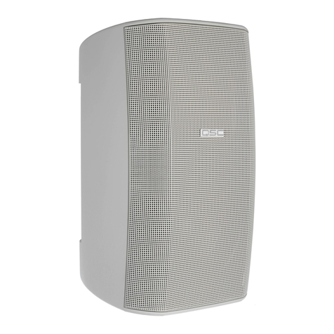
QSC AcousticDesign Series Instructions for use

Hardware User Manual
AcousticDesign™ Series Direct Weather Landscape Loudspeakers
AD-DWL.180
AD-DWL.360
AD-DWL.SUB
AD-DWL.BASE
TD-001650-01-A
*TD-001650-01*

2
EXPLANATION OF TERMS AND SYMBOLS
The term “WARNING!” indicates instructions regarding personal safety. If the instructions are not followed the result may be bodily
injury or death.
The term “CAUTION!” indicates instructions regarding possible damage to physical equipment. If these instructions are not followed, it
may result in damage to the equipment that may not be covered under the warranty.
The term “IMPORTANT!” indicates instructions or information that are vital to the successful completion of theprocedure.
The term "NOTE" is used to indicate additional useful information.
The lightning flash with arrowhead symbol in a triangle alerts the user to the presence of uninsulated dangerous voltage within
the product’s enclosure that may constitute a risk of electric shock to humans.
The exclamation point within a triangle alerts the user to important safety, operating, and maintenance instructions in this
manual.
IMPORTANT SAFETY INSTRUCTIONS
WARNING!: While it is possible for one person to lift a loudspeaker, it is important to use proper lifting techniques.
Suggested reading: OSHA Technical Manual (OTM) > Back Disorders and Injuries:
https://www.osha.gov/otm/
1. Keep these instructions.
2. Heed all warnings.
3. Follow all instructions.
4. Clean only with a damp cloth.
5. Do not install near any heat sources such as radiators, heat registers, stoves, or other apparatus (including amplifiers) that produce
heat.
6. Only use attachments/accessories specified by the manufacturer.
7. Refer all servicing to qualified service personnel.
8. Adhere to all applicable, local codes.
9. Consult a licensed, professional engineer when any doubt or questions arise regarding a physical equipment installation.
Environmental
• Operating Temperature Range: -30°C to 50°C
• Relative Humidity: 0 to 100% RH, non-condensing
Specifications and Dimensions
Product specifications and dimension drawings for the AD-DWL Series can be found online at qsys.com.

3
RoHS Statements
The QSC AD-DWL loudspeakers are in compliance with European Directive 2011/65/EU – Restriction of Hazardous Substances
(RoHS2).
The QSC AD-DWL loudspeakers are in compliance with “China RoHS” directives per GB/T24672. The following table is provided for
product use in China and its territories.
QSC AD-DWL Loudspeakers
部件名称
(Part Name)
有害物质
(Hazardous Substances)
铅
(Pb)
汞
(Hg)
镉
(Cd)
六价铬
(Cr(vi))
多溴联苯
(PBB)
多溴二苯醚
(PBDE)
电路板组件
(PCB Assemblies)
X O O O O O
机壳装配件
(Chassis Assemblies)
X O O O O O
本表格依据 SJ/T 11364 的规定编制。
O: 表示该有害物质在该部件所有均质材料中的含量均在 GB/T 26572 规定的限量要求以下。
X: 表示该有害物质至少在该部件的某一均质材料中的含量超出 GB/T 26572 规定的限量要求。
(目前由于技术或经济的原因暂时无法实现替代或减量化。)
This table is prepared following the requirement of SJ/T 11364.
O: Indicates that the concentration of the substance in all homogeneous materials of the part is below the relevant threshold
specified in GB/T 26572.
X: Indicates that the concentration of the substance in at least one of all homogeneous materials of the part is above the
relevant threshold specified in GB/T 26572.
(Replacement and reduction of content cannot be achieved currently because of the technical or economic reason.)

4
• (1) AD-DWL.180, AD-DWL.360, or AD-DWL.SUB
• (1) collar
• (4) collar Torx M6 screws
• (1) Torx bit
• (1) installation template
• (1) paint mask for AD-DWL.180, (2) paint masks for
AD-DWL.360*
* Paint mask not required for AD-DWL.SUB. For painting
instructions, see the Self Help Portal.
Four M10 or 3/8” bolts
on 120mm (4.72”) diameter circle
— Figure 1 —
Installation on Concrete or Other Hard Surfaces
Hard surface installation requires four M10 or 3/8" drop-in anchor
bolts, eight nuts, and eight washers (not supplied). The bolts must be
long enough to provide 65mm (2.5") of usable thread above the
surface level.
Prepare the surface
NOTE:
Before proceeding, be aware of the location of
conduit under the loudspeaker location and the intended
orientation of the loudspeaker – for example, facing
parallel to another hard surface, such as a sidewalk or
patio.
1. Use the supplied installation template to mark the location for the
four drop-in anchor bolts as close to the center of each arc as
possible, as shown in Figure 1.
2. Install the anchor bolts (not supplied) into the mounting surface.
Mount the collar
The rotational orientation of the collar determines the
aim of the loudspeaker. The collar can rotate ± 26°
from the arc center.
1. On each anchor bolt, place a bottom nut and
washer. These are used to level the collar.
2. Place the collar on the bottom washers. Using a
bubble level, adjust the nuts so that the collar is
horizontal and that all washers are in contact with
the collar flange. See Figure 2.
NOTE:
There must be no gap between the
washers and the collar flange.
3. Rotate the collar to the exact desired position,
verify levelness, and then secure the collar by
attaching a top washer and nut for each bolt. See
Figure 3.
4. Tighten all top nuts to a recommended torque of
81 kgf.cm (70 lbf.in).
Hard Surface
Flange
Nut Washer
— Figure 2 —
Hard Surface
Flange
Nut
Washer
— Figure 3 —
What's in the Box
5
Concrete/Surface Installation – Continued
Wire the loudspeaker
1. Lay the loudspeaker on the ground with its open base near the installed collar.
2. Make a solid and waterproof connection between the loudspeaker's wire pig-
tail and the output from your amplifier, with red being positive (+) and black
being negative (-). Wire in parallel to other AD-DWL Series loudspeakers as
needed. See Figure 4.
NOTE:
Gel-filled wire nuts, WAGO gel boxes, or equivalent are
recommended for wire connections.
3. Adjust the Transformer Settings dial to the desired setting for your installation,
depending on your AD-DWL Series model:
AD-DWL.180 and AD-DWL.360 (Figure 5), AD-DWL.SUB (Figure 6).
Attach the loudspeaker
1. Tuck the wires into the hollow loudspeaker base.
2. Lower the loudspeaker onto the collar and attach them together
with the four supplied M6 Torx screws. See Figure 7.
3. Tighten the screws to a recommended torque of 23 kgf.cm (20
lbf.in).
— Figure 5 — — Figure 6 —
Four M6 Torx
screws
— Figure 7 —
— Figure 4 —
Amplifier
++ + +
__ _ _

6
In-Ground Installation
In-ground installation requires the AD-DWL.BASE* accessory, which comes with all the hardware needed (bolts, nuts, and washers) to
mount the loudspeaker collar to the BASE.
Prepare the BASE
Remove the side knockouts as needed to allow for attaching conduit for the speaker wiring between the loudspeakers and amplifier.
Refer to Figure 8 for an example.
NOTE:
Conduit knockouts in the AD-DWL.BASE accommodate standard 12mm (3/8") conduit clamps.
Grade Level
3/8” Conduit
From Amplifier
To Other
Speakers
— Figure 8 —
Auger Stake
(optional, not supplied)
— Figure 9 —
Install the BASE
NOTE:
Keep the disposable round lid attached to the top of the BASE during
installation to prevent debris from entering the cavity.
1. For each BASE unit, dig a hole at least 275mm (11") deep and 200mm (8") in diameter.
2. Run conduit and wiring as needed.
3. Place the BASE into the hole, ensuring that the top of the BASE is flush with grade level. To
assist with stabilizing the BASE in soft or unstable soil, you can optionally attach an auger
stake (not supplied) through the bottom knockout, as shown in Figure 9.
NOTE:
Before proceeding, ensure that the BASE is oriented such that a pair of
bolts is parallel with the intended aim of the loudspeaker tweeter – for example,
facing a surface such as a sidewalk or patio. See Figure 10.
4. Fill the hole surrounding the base with soil or concrete. Compress the soil to help prevent
movement of the BASE and loudspeaker. (Adding water to the backfill can help with this.)
For a more secure installation, optionally anchor the BASE by pouring concrete around its
body – up to 90% of the BASE's overall height.
Tweeter
Tweeter BASE
— Figure 10 — *AD-DWL.BASE accessory has not been evaluated by UL.

7
In-Ground Installation – Continued
Mount the collar
The rotational orientation of the collar (Figure 11) determines the
aim of the loudspeaker. The collar can rotate ± 26° from the arc
center.
NOTE:
Refer to Figure 12 for proper placement of the
nuts and washers described in the following steps.
1. Remove the top nuts and washers from each of the four BASE
bolts and set them aside.
2. Discard the protective lid.
3. Thread the bottom nuts and washers all the way down to the
Nyloc nuts. (Do not loosen the Nyloc nuts at the base of the
bolts, as these secure the bolts in place.)
4. Place the collar on the bottom washers of the BASE. Using a
bubble level, adjust the nuts so that the collar is horizontal and
that all washers are in contact with the collar flange. See Figure
13 .
NOTE:
There must be no gap between the washers and
the collar flange.
5. Rotate the collar to the exact desired position, verify levelness,
and then secure the collar by attaching a top washer and nut for
each bolt.
6. Tighten all top nuts to a recommended torque of 81 kgf.cm (70
lbf.in).
Collar
Top Nuts and
Washers
Collar
Bottom Nuts
and Washers
BASE
— Figure 11 —
— Figure 12 —
Flange
Nyloc Nuts
(Do not loosen)
Top Nuts and Washers
Bottom Nuts and Washers
Grade Level BASE
— Figure 13 —

8
In-Ground Installation – Continued
Wire the loudspeaker
1. Lay the loudspeaker on the ground with its open base near the installed collar.
2. Make a solid and waterproof connection between the loudspeaker's wire
pig-tail and the output from your amplifier, with red being positive (+)
and black being negative (-). Wire in parallel to other AD-DWL Series
loudspeakers as needed. See Figure 14.
NOTE:
Gel-filled wire nuts, WAGO gel boxes, or equivalent are
recommended for wire connections.
3. Adjust the Transformer Settings dial to the desired setting for your installation,
depending on your AD-DWL Series model:
AD-DWL.180 and AD-DWL.360 (Figure 15), AD-DWL.SUB (Figure 16).
Attach the loudspeaker
1. Tuck the wires into the hollow loudspeaker base.
2. Lower the loudspeaker onto the collar and attach them together
with the four supplied M6 Torx screws. See Figure 17.
3. Tighten the screws to a recommended torque of 23 kgf.cm (20
lbf.in).
— Figure 15 — — Figure 16 —
Four M6 Torx
screws
— Figure 17 —
— Figure 14 —
Amplifier
++ + +
__ _ _

9
Self Help Portal
Read knowledge base articles and discussions, download software and firmware, view product documents and training videos, and
create support cases.
qscprod.force.com/selfhelpportal/s/
Customer Support
Refer to the Contact Us page on the Q-SYS website for Technical Support and Customer Care, including their phone numbers and
hours of operation.
qsys.com/contact-us/
Warranty
For a copy of the QSC Limited Warranty, go to:
qsys.com/support/warranty-statement
®
© 2023 QSC, LLC. All rights reserved. QSC and the QSC logo, Q-SYS, and the Q-SYS logo are registered trademarks of QSC, LLC in the U.S. Patent and Trademark Office
and other countries. Patents may apply or be pending. All other trademarks are the property of their respective owners.
qsc.com/patents
qsys.com/patents
Other manuals for AcousticDesign Series
5
This manual suits for next models
4
Table of contents
Other QSC Speakers manuals

QSC
QSC AcousticPerformance AP-5122m User manual

QSC
QSC ILA System v2 User manual

QSC
QSC AcousticDesign AD-C6T User manual

QSC
QSC K8 User manual

QSC
QSC MD-FP122/66 User manual

QSC
QSC E 12 User manual

QSC
QSC WideLine-10 WL2102 User manual

QSC
QSC MH-1075C-F User manual

QSC
QSC SR-1000 User manual

QSC
QSC SR-800 User manual