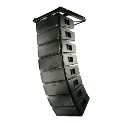
QSC LA112-KIT-SA User manual

LA-KIT-I Quick Start Guide
IMPORTANT SAFETY INSTRUCTIONS
WARNING!: TO PREVENT FIRE OR ELECTRIC SHOCK, DO NOT EXPOSE THIS EQUIPMENT TO RAIN OR
MOISTURE.
WARNING!: Before placing, installing, rigging, or suspending any loudspeaker product, inspect all hardware,
suspension, cabinets, transducers, brackets and associated equipment for damage. Any missing, corroded, deformed, or
non-load rated component could significantly reduce the strength of the installation or placement. Any such condition
severely reduces the safety of the installation and should be immediately corrected. Use only hardware which is rated for
the loading conditions of the installation and any possible short-term, unexpected overloading. Never exceed the rating of
the hardware or equipment. Consult a licensed, professional engineer regarding physical equipment installation. Ensure
that all local, state and national regulations regarding the safety and operation of loudspeakers and related equipment are
understood and adhered to.
WARNING!: The LA108 loudspeaker weighs 13.7 kg (30.1 lb), and the LA112 loudspeaker weighs 21.4 kg (47.2 lb).
Use proper precautions when lifting or moving. During assembly and disassembly, make sure the loudspeakers are
properly, physically supported throughout the entire process. While it is possible for one person to lift a LA108 or LA112
loudspeaker, it is important to use proper lifting techniques. Suggested reading: OSHA Technical Manual on Back
Disorders and Injuries.(http://www.osha.gov/dts/osta/otm/otm_vii/otm_vii_1.html#app_vii:1_2).
1. Keep these instructions.
2. Heed all warnings.
3. Follow all instructions.
4. Do not use this apparatus near water.
5. Clean only with a dry cloth.
6. Install in accordance with the manufacturer's instructions.
7. Do not install near any heat sources such as radiators, heat
registers, stoves, or other apparatus (including amplifiers) that
produce heat.
8. This apparatus shall not be exposed to dripping or splashing
water, and no object filled with liquids such as cups or vases
shall be placed on the apparatus.
9. To reduce the risk of electric shock, the power cord shall
be connected to a mains socket with a protective earthing
connection.
10. Protect the power cord from being walked on or pinched,
particularly at plugs, convenience receptacles, and the point
where they exit from the apparatus.
11 . Only use attachments/accessories specified by the
manufacturer.
12. Unplug this apparatus during lightning storms or when
unused for long periods of time.
13. Refer all servicing to qualified service personnel. Servicing
is required when the apparatus has been damaged in
any way, such as when the power-supply cord or plug is
damaged, liquid has been spilled or objects have fallen into
the apparatus, and/or the apparatus has been exposed to
rain or moisture, does not operate normally, or has been
dropped.
14. The appliance coupler (AC Mains plug) is the AC mains
disconnect device and shall remain readily operable after
installation.
15. Adhere to all applicable, local codes.
16. Consult a licensed, professional engineer when any doubt or
questions arise regarding a physical equipment installation.
17. Suspension of this product should be done by qualified
persons following safe rigging practices. Other limitations
may apply.
18. Use only the recommended system components and
suspension hardware intended for use with this product as
directed by this manual.
TD-001648-01-A
*TD-001648-01*
2
Rigging Safety Regulations:
• 2006/42/EC
• EN ISO 12100-1: 2004
• EN1991-1 / EN1993-1-1 / EN1993-1-8 / EN1999-1-1
• DGUV Vorschrift 17/18
• ANSI E1.8-2018
General Rules for Suspension
• Consult a professional mechanical or structural engineer, licensed in the jurisdiction of the sound system installation, to review, verify,
and approve all attachments to the building or structure.
• Employ the services of a certified, professional rigger for hoisting, positioning, and attaching the equipment to the supporting
structure.
• Correct use of all suspension hardware and components is imperative in sound system suspension and deployment.
• Always calculate suspended loads before lifting to ensure suspension components and hardware are used within their respective
load limits.
• Consult local codes and regulations to fully understand the requirements for suspended loads in the venue in which equipment will
be suspended.
• Use only dedicated QSC LA108-AF and/or QSC LA112-AF array frames or the QSC LA-KIT-I installation kit for suspending a
loudspeaker array. Further details can be found below.
• Be absolutely certain of the integrity of any structural member intended to support suspended loads. Hidden structural members can
have hidden structural weakness.
• Never assume anything! Owner or third-party supplied suspension attachment points may not be adequate for suspending the
loads.
• Before lifting, always inspect all components (enclosures, suspension brackets, pins, frames, bolts, nuts, slings, shackles, etc.) for
cracks, wear, deformation, corrosion, missing, loose, or damaged parts that could reduce the strength of the assembly. Discard any
worn, defective, or suspect parts and replace them with new, appropriately load-rated parts.
Shock Loading
When a load is moved or stopped, its static weight is magnified. Sudden movements can magnify the static weight several times. This is
called "shock loading."
The effects of shock loading can be instantaneous, or it can remain undetected. Proper preparation for shock loading requires careful
planning and knowledge of equipment, suspension, and lifting practices. Shock loading is most often the result of lifting and installation,
but natural forces (winds, earthquakes, etc.) can create shock loads several times the static load.
Shock loading poses a danger to equipment and workers. Because of this, structures and suspension equipment must be capable of
supporting several times the weight of the suspended equipment.
Flown Deployment with the LA-KIT-I
LA-KIT-I contains two (2) Shackle Adapters and one (1) M10 Pullback Eyebolt that allows users to deploy no more than three (3) LA112
or four (4) LA108 loudspeakers in an array configuration.
Attaching the Shackle Adapters to a Loudspeaker
1. Attach two Shackle Adapters to the Front Strikes on the left side of the loudspeaker.
Install one Shackle Adapter facing forward and one Shackle Adapter facing backward.
2. Attach two Shackle Adapters to the Front Strike on the right side of the loudspeaker.
Install one Shackle Adapter facing forward and one Shackle Adapter facing backward.
—Figure1—

3
WARNING!: Two (2) Shackle Adapters MUST be attached to both sides of the Front Strikes, and each pair of shackles
MUST be “mirrored” with one facing forward and one facing backward. Failure to do so could result in physical damage
and/or personal injury.
—Figure2—
Attaching Loudspeakers for an Array
1. After attaching the Shackle Adapters and hanging the first loudspeaker of the array, set the loudspeaker’s Locking Levers to the
middle (ADD+) position on both sides.
2. Hang both Front Strikes of the lower loudspeaker onto the Front Hooks of the upper loudspeaker.
3. Lift rear handles of the lower loudspeaker until the Angle Bar connects to the Rear Hooks of the upper loudspeaker on both sides,
making a click sound.
4. Push the Locking Levers down (LOCK) on both sides of the upper loudspeaker.
5. Repeat steps 1-4, for up to a total of three (3) LA112 or four (4) LA108 loudspeakers.
—Figure3—
WARNING!: Do NOT hang more than three (3) LA112 or four (4) LA108 loudspeakers in an array with the LA-KIT-I.
IMPORTANT:
When rigging loudspeakers together, attach the bottom unit to the one above using the QSC
RapidDeploy™ latching mechanism on the upper unit.
WARNING!: Make sure the loudspeakers are physically, properly aligned; if not, the latching system may not properly
engage, and the loudspeakers could separate causing physical damage and/or personal injury.
WARNING!: QSC strongly recommends having a dedicated rigging point for each shackle adapter. "Bridling" up to
three (3) LA112 or four (4) LA108 loudspeakers is allowed as long as the angle of the bridle is less than 90 degrees. Using
a single rigging point to bridle between the two shackle adapters in excess of 90 degrees and the allowed number of
loudspeakers could result in damage to or deformation of the front strikes, reducing the safety of the integrated rigging
hardware.

4
Attaching the Eyebolt
Screw the M10 Pullback Eyebolt into the threaded insert
located on the back of the lowest loudspeaker of the
array for a third pick-point to further support the system.
WARNING!: Do not exceed the
Working Load Limits of the M10 Pullback
Point as stated in the table below.
Working Load Limits
Model Individual
Component Weight
7:1 Safety Factor 10:1 Safety Factor 12:1 Safety Factor
LA108 M10 Pullback Point Built into rear of product 92.1 kg / 203 lb 64.4 kg / 142 lb 53.5 kg / 118 lb
LA112 M10 Pullback Point Built into rear of product 80.3 kg / 177 lb 56.2 kg / 124 lb 46.7 kg / 103 lb
Splay Angle Adjustment for Flown Deployment
The splay angles for loudspeakers within an array can be adjusted individually to 1.5°, 6°, and 12°.
NOTE: See the LA108 and LA112 User Manual for further details on splay angle
adjustments.
—Figure4—
1.5°
6°
—Figure5—
Self Help Portal
Read knowledge base articles and discussions, download software and firmware, view product documents and training videos, and
create support cases. Go to qscprod.force.com/selfhelpportal/s/.
Customer Support
Refer to the Contact Us page on the QSC website for Technical Support and Customer Care, including their phone numbers and
hours of operation. Go to qsc.com/contact-us/.
Warranty
For a copy of the QSC Limited Warranty, go to qsc.com/support/warranty-statement/.
®
© 2022 QSC, LLC. All Rights Reserved.
QSC, LLC’s trademarks include but are not limited to QSC®and all trademarks are listed under www.qsc.com/trademarks,
some of which are registered in the U.S. and/or other countries.
This manual suits for next models
1
Table of contents
Other QSC Speakers manuals

QSC
QSC E Series User manual

QSC
QSC AD-S282H User manual

QSC
QSC AcousticCoverage Series User manual

QSC
QSC MD-FP122/66 User manual

QSC
QSC AcousticDesign AD-S52T User manual

QSC
QSC SR-110 User manual

QSC
QSC E 12 User manual

QSC
QSC K10 User manual

QSC
QSC Acoustic Design Series User manual

QSC
QSC WL2102 User manual

QSC
QSC KLA12 User manual

QSC
QSC AcousticDesign AD-C4T User manual

QSC
QSC AcousticDesign Series Instructions for use

QSC
QSC AcousticDesign AD-S82 User manual

QSC
QSC SR-18 User manual

QSC
QSC MHV-1090 User manual

QSC
QSC SR-110B User manual

QSC
QSC SR-1290 User manual

QSC
QSC CSM10 User manual

QSC
QSC K.2 series User guide