1675 MacArthur Blvd., Costa Mesa, CA, 92626 USA
Main Number (714) 754-6175or toll free (USA only)(800) 854-4079
Customer Service(714) 957-7150 or toll free (USA only) (800) 772-2834
Important Safety Precautions & Explanation of Symbols
Install in accordance with QSC Audio Product's instructions and under the supervision of a licensed Professional Engineer.
WARNING! The exclamation point within an equilateral triangle is intended to alert the user to the presence of important operating
and maintenance (servicing) instructions in this manual.
•Before placing, installing, rigging, or suspending any speaker product, inspect all hardware, suspension,
enclosures, transducers, brackets and associated equipment for damage. Any missing, corroded, deformed, or
non-load rated component could significantly reduce the strength of the installation or placement. Any such
condition severely reduces the safety of the installation and should be immediately corrected. Use only hard-
ware which is rated for the loading conditions of the installation and any possible short-term, unexpected
overloading. Never exceed the rating of the hardware or equipment.
•Consult a licensed, Professional Engineer regarding physical equipment installation. All local, state and
national regulations regarding the safety and operation of equipment are understood and adhered to.
•Use only load rated hardware to attach to the eyebolts or pull-back bar when suspending these products.
•Do not suspend these products from any structural element on the enclosure other than the load rated M10
suspension points.
•Do not suspend the HPR152i or HPR153i horizontally under any circumstances using this or any other hard-
ware.
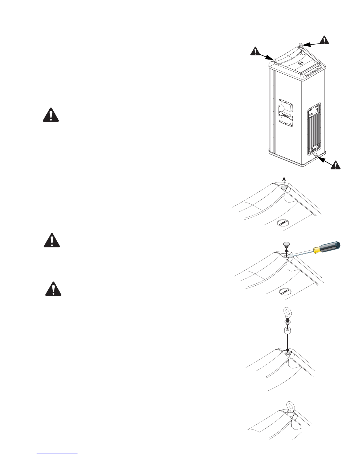
Vertical Suspension of the HPR122i
Install Two Top-surface Eyebolts
1- Remove the factory installed M10 flat-head screws from the top of the enclosure using a 6mm
hex wrench.
2- Thread an eyebolt into each of the enclosure’s threaded inserts;do not use flat washers or
standoffs on the top eyebolts. Tighten eyebolts.
Install One Pull-back Eyebolt
Attherearoftheenclosure,justbelowtheamplifiermodule,isaM10flat-headscrewwhichmust
be removed and have an eyebolt installed in its place (6mm hex wrench needed).
1- Remove the factory installed M10 flat-head screwfrom the enclosure using a 6mm hex wrench.
2- Thread an eyebolt into the enclosure’s threaded insert; do not use a flat washer or standoff on
the pull-back eyebolt. Tighten eyebolt.
•Do not use the eyebolt standoffs, flat washers, or pull-back bar
when suspending the HPR122i loudspeaker vertically.
•Note! Be sure to tighten each eyebolt until shoulder is snug
against the enclosure. Tighten the eyebolts down and then con-
tinue to rotate until they are positioned as desired.
•Bar, pull-back, black, PB122i, 1 each
•Gasket, adhesive-backed, 2 each
•Eyebolt, M10, steel, 3 each
•Screw, buttonhead, hex drive, M10-1.5x45mm, 1 each
•Spacer, aluminum, 2 each
•Spring washer, conical, M10, steel, 2 each
•Hex nut, M10-1.5, steel, 1 each
•Lock washer, spring, M10, steel, 2 each
•Flat washer, M10, steel, 2 each
HPR SUS KIT 122 User Manual
ThissuspensionkitisrequiredforhorizontalsuspensionoftheQSCHPR122ifroma solid structureorfor the vertical suspension of the QSC HPR122i,
HPR152i or HPR153i from a solid structure.
Contents:
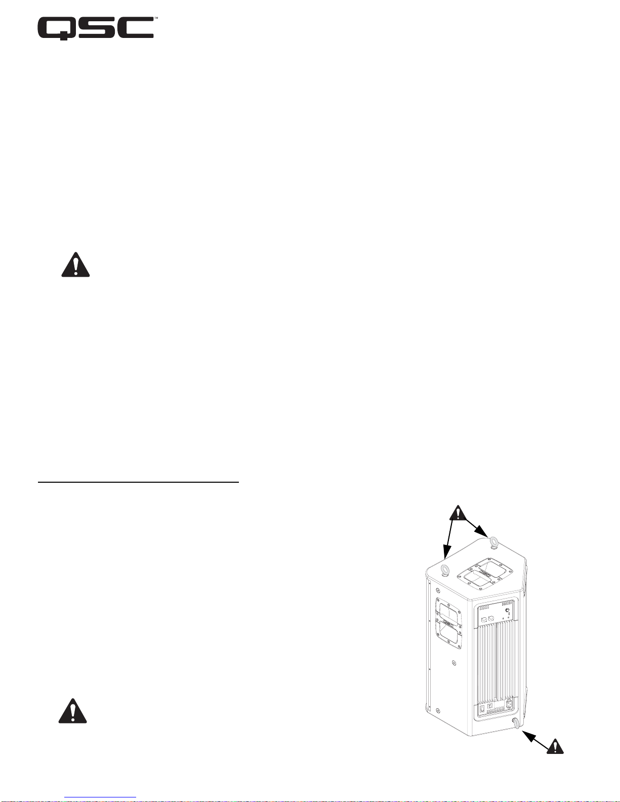
Eyebolt installation loca-
tionsforverticalsuspension
of the HPR122i loudspeaker.