Qtx SC100 User manual

SC100
Item ref: 178.192UK
Suitcase PA
User Manual
Version 1.0

178.192UK User Manual
Caution: Please read this manual carefully before operating
Damage caused by misuse is not covered by the warranty
Introduction
Thank you for choosing the QTX SC100 Suitcase PA for your portable sound requirements.
This system has been designed to offer a complete stereo PA solution for small to medium applications
in a convenient, easy-to-carry format.
Please read and keep this guide to help get the best results and avoid damage to your new PA.
Unpacking
The SC100 system is provided in 2 parts:
1: Suitcase PA with central mixer-amp section, 2 x clip-on speakers, zip-bag with 2 x speaker
leads, 1 microphone + mic lead, IEC mains lead(s)
2: Pair of tripod speaker stands and carry bag.
Check that all are present and if any part is missing or broken, contact your retailer immediately.
Caution
This product contains no user-serviceable parts so make no attempt to try to fix or modify this item
yourself as this will invalidate the warranty. We recommend you keep the original package and proof of
purchase for any possible replacement or returned demand.
Warning
To prevent the risk of fire or electric shock, do not expose this appliance to rain or moisture. To prevent
electric shock do not remove the mixer-amp housing cover. No user serviceable parts inside. Refer
servicing to qualified service personnel.
THIS UNIT MUST BE EARTHED. Ensure that the mains supply has a reliable Earth connection.
Safety
Prior to connecting mains, check the supply voltage is correct and the IEC mains lead is OK.
Avoid ingress of water or particles into the enclosure.
If the internal IEC fuse blows, refer the unit to qualified service personnel
Placement
Keep the main unit out of direct sunlight and away from heat sources.
Place the unit in an upright position during use and storage.
Keep the unit away from moisture or dusty environments.
Mount the speakers onto the stands provided on a stable surface with the tripods opened sufficiently.
Cleaning
Use a soft cloth with a neutral detergent to clean the cabinet, panel and controls.
To avoid damage, do not use solvents to clean this equipment.

178.192UK User Manual
Panel Layouts
1
Audio player & controls
2
SD/MMC card slot
3
USB port
4
Channel 4/5 volume controls
5
Channel 1 volume fader
6
Channel 1 tone controls
7
Channel 2 volume fader
8
Channel 2 tone controls
9
Channel 3 volume fader
10
Channel 3 tone controls
11
Channel 4/5 L/R stereo reverse
12
mp3 playback to main output
13
Channel 4/5 tone controls
14
5-band graphic equalizer
15
Main output VU meters
16
DSP effects display
17
DSP effects program select
18
DSP effects level control
19
Headphones output level
20
Master L+R volume faders
21
Channel 1 XLR mic. input
22
Channel 1 jack line input
23
Channel 2 XLR mic. input
24
Channel 2 jack line input
25
Channel 3 jack mic/guitar input
26
Channel 3 jack line input
27
Channel 4/5 (L/R) RCA inputs
28
Main L+R RCA line outputs
29
Mono jack output
30
Stereo jack headphone output
31
IEC mains inlet & fuse holder
32
Power on/off rocker switch
33
Left speaker output jack
34
Right speaker output jack

178.192UK User Manual
Setting up
Remove the tripod stands from the carry bag and extend each tripod base so that the legs are
sufficiently spaced to support each speaker on a stable and even surface. Extend the upper telescopic
section to the required height.
Open the SC100 “suitcase”by unfastening the clips at either side of the handle and lifting the centre
console lid. With the lid opened fully, it is possible to lift out each of the 2 speakers, which should be
fitted to the top of the tripod stands.
Unzip the bag adjacent to the mixer-amp console and remove all accessories.
Connections
Connect the mixer-amp to both speakers using the included speaker jack leads (33, 34)
If required, connect the included microphone to channel 1 or 2 (22, 24) using the supplied XLR lead.
XLR sockets on channels 1 & 2 are for microphones, whereas the jack sockets (23, 25) are for mono
line inputs. Use either mic or line input, not both together into a single channel.
(Line input can be CD player, computer sound card, sub mixer etc.)
Channel 3 has a jack input (25) for mic or instrument (guitar, keyboard etc.) and another jack (26) for
line input.
Channel 4/5 is a stereo channel with 2 RCA sockets (27) for left and right line inputs.
If the stereo mix of all inputs is to be fed onto additional PA or recording equipment, there is a stereo
line output via RCA sockets (28) which should be linked to stereo line inputs of the external equipment.
There is also a mono line output (ideal for a wedge monitor) via a jack socket (29)
Finally, for monitoring the mix through headphones, there is a stereo phones jack output (30)
When all signal connections are completed, connect the IEC inlet (31) to a suitable mains supply using
the included power lead.
Initial settings
•Set all faders (5, 7, 9, 20) to the zero mark (fully down)
•Set all tone controls (6, 8, 10, 12) to the 12 o’clock position (vertical)
•Set all Graphic EQ faders (14) to the zero mark (mid position)
•Turn channel 4/5 rotary controls (4) to the zero mark (fully down)
•Turn the EFFECTS and PHONES rotary controls to zero mark (fully down)
The SC100 PA is now ready to be switched on

178.192UK User Manual
Operation
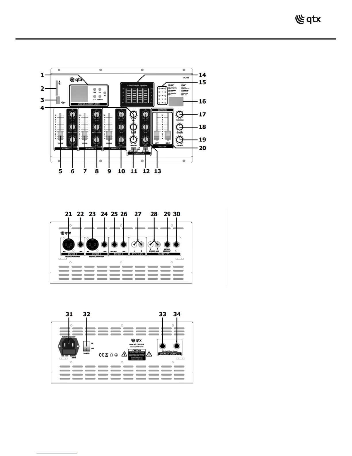
Press the power rocker switch (32) to the “ON”position and it will light.
The audio player display (1) and DSP effects display (16) will also be lit.
To check the system, turn up the Master Volume faders (20) part way, then whilst speaking into the
wired microphone, turn up its channel fader (5, 7) gradually until you can hear it through the speakers.
You may alternatively use the audio player to check the system (see the “Audio Player”section below)
Continue to increase the Master and channel volumes to the required level, always checking that the
main output VU meters are not lighting the “CLIP”LEDs. Repeat this process for other channel inputs.
Tone adjustment
At this point you may prefer to set the tone of the sound by adjusting the tone controls (6, 8, 10, 13)
Three rotary controls per input channel govern LOW, MID and HIGH (or BASS, MIDDLE and TREBLE)
LOW controls the amount of low end “thump”or “warmth”and HIGH controls the “hiss”or “brightness”
MID controls the detail in between LOW and HIGH and can determine the prominence within a mix.
For channel inputs 1 and 2, MID is a MID CONTOUR control, which alters the character of the middle
accent by shifting the area of tone that it affects.
For tone controls, 12 o’clock (vertical) is the neutral (zero) position and moving to the left cuts the level
whilst moving to the right boosts the level. MID CONTOUR also changes character from left to right.
Overall tone character is adjusted using the 5-band graphic EQ (14), which can be considered as a set
of master tone controls governing Low / Low-Mid / Mid / High-Mid / High frequencies.
The centre position for each slider is the neutral (zero) setting.
Moving up from zero boosts the frequencies whilst moving down from zero cuts the frequencies.
Master output
When all inputs have been adjusted to suit, check the main output LEDs again for clipping.
It is acceptable for the CLIP LEDs to light momentarily at maximum volume on the loudest accents of
the sound but they should never be lit for more than a brief instant. If this happens, reduce the Master
volume faders or channel faders as necessary.
DSP Effects
For sound effects, such as Reverb or Echo for vocalists, the SC100 features a 16-program DSP effects
section (DSP stands for Digital Signal Processor). Settings for this section are displayed in a window
near to its controls (16) with a list of all 16 effect types alongside it.
All input channels are routed through the effects section except for the media player. Effect type is
selected by turning the PROGRAM rotary control (17) and the level of effect fed into the main mix is
adjusted using the EFFECT rotary control (18)

178.192UK User Manual
Feedback
When using microphones with the SC100, point them away from the speakers to avoid feedback.
This is when the microphone can hear its own output through the speakers and causes a loud howl or
squeal through the speakers. Lowering some of the graphic equalizer sliders can also help to avoid this.
Monitoring
The SC100 has a jack output to enable the main mix to be heard through stereo headphones (30)
The headphones output volume is adjusted using the PHONES rotary control (19). Care should be taken
to keep listening levels within normal limits to avoid hearing damage.
The main mix is also fed as a mono output to the MONO LINE OUT jack (29), which is controlled by the
MASTER L+R faders (20)
Stereo input
Inputs for channel 4/5 are fed in stereo to the L/R main mix. Individual volume levels for the channel
4/5 inputs are governed by the LEFT and RIGHT controls, whereas the overall volume for the stereo
mix is governed by the MASTER control (4).
In some instances, specialist playback material for karaoke or aerobic instruction have a different mix
on the left and right channel. The SC100 has a LEFT/RIGHT SWAP switch to enable the L+R inputs to
be reversed. Channel 4/5 tone controls (13) affect both left and right inputs.
Audio player
The SC100 has an audio player section (1) which can play mp3 files stored on a USB stick or SD card.
To enable playback, press in the MP3 TO MAIN button (12). Control buttons are as shown below.
Previous track
Next track
Play/Pause
Repeat mode: single track / all tracks
USB/SD
Select memory device: USB stick or SD card
Insert the USB or SD card with mp3 files stored into the USB port (3) or SD card slot (2).
If playback does not start immediately, press the Play/Pause button.
To change track for playback, use the Previous Track and Next Track buttons.
To select a continuous play of one or all tracks, press the Repeat button.
To switch between USB or SD memory devices, press the USB/SD button.
Packing away
Before switching the SC100 power off, it is important to set all level controls back to minimum to avoid
any loud pops or clicks through the speakers. Pack all accessories away carefully and avoid trapping
leads or connectors when the lid is closed.

178.192UK User Manual
Specifications
Power supply
100-240Vac, 50/60Hz (IEC)
Fuse
T1.6AL / 250V
Power consumption max.
200W
Output power
2 x 50Wrms @ 4 Ohms
Mic/line inputs
2 x balanced XLR/jack, 1 x unbalanced jack
Stereo input
L+R RCA
LF drivers
2 x 112mmØ (4“) per speaker
HF drivers
25mmØ (1“) silk dome tweeter per speaker
Speaker impedance
4 Ohms
Line output
L+R RCA and mono 6.3mm jack
Headphone output
Stereo 6.3mm jack
Effects
16 preset DSP effects
Frequency response: amplifier
40Hz - 25kHz
THD
<0.8% @ rated output
S/N ratio
85dB
Speaker outputs
L+R 6.3mm jack
Dimensions
630 x 412 x 170mm
Weight
14kg

178.192UK User Manual
Disposal: The “Crossed Wheelie Bin” symbol on the product means that the product is classed as Electrical or
Electronic equipment and should not be disposed with other household or commercial waste at the end of its useful life.
The goods must be disposed of according to your local council guidelines.
Errors and omissions excepted.
Copyright© 2017. AVSL Group Ltd.
Table of contents
Other Qtx Amplifier manuals