QUAD 33 User manual


Contents
Introduction
Installation
Mounting the units
Connections
Pickup
(Disc)
AdaPtor ...
TapeAdaptor
lllustrations Page
Installation
Schematic 3
Pickupandmotor wiring 4
5
6
7
8
8
9
10
1l
l2
l6
23
MountingtheQuad33
Connections
to Quad303
Quad
33controls
lssue
4/3m/271
DIN plugs
DISC
input
Disc Adaptor Board
Tape and Radio inputs
TapeAdaptor Board
Tape Adaptor adjustments
Quad33rear panellaYout
Quad33performancecurves
Quad303
performancecurves
Page
2
J
4&5
6to10
Initial Checks
andOPeretion
Controls
Loudspeaker
phasing
Loudspeakerposition
Operation
Summary
Service
Specifications
Guarantee
THE
ACOUSTICAL
MANUFACTURING
CO.
ST. PETERS
ROAD, HUNTINGDON,
ENGLAND
Telephone:
Huntingdon
(0480) 2561
Telegrams:
Acoustical
Huntingdon
13
13to 15
7
l0
l5
I7
l8
18
to 23
24
LTD.
l9

QUAD
fortheclosest
approach
to the
originalsound
INTRODUCTION
This amplifier has beendesignedto provide the best
possiblequality of reproduction but it must be borne
in mind that the standardof performance
of the com-
plete equipmentwill be limited by that of the poorest
link in thechain. Thus,thegramophone
motor,pickup,
loudspeaker,etc.,shouldallreceive
careful
consideration
if full advantage
is to betakenof the capabilitiesof the
amplifier.
A complete
installationis shownin Fig. I and the
samobasicarrangement
will apply in wholeor in part,
whateverassociated
equipmentis usedwith the Quad
33. Installation is quite straightforward and should
present
no difficulty to the intelligent enthusiast
pro-
vided the following notesare observed.
Pleasenote
thatthree
printed
circuitboards
fromthe
Quad
33are
packed
separatelyfor safe
transit. These
must be insertedduring installation. See
Fig. 3 and
alsoinstructions
containedin the packing.
It
Page Two

INSTALLATION
Normally equipment of this type may be either
mounted in a wide varietryof housings or usedfree-
standing, and if you are designingyour own layout it
might beadvisableto assemble
all theparts in a mock-
up form before deciding on the final arrangement,
just
to make sure there are no unforeseendifficulties of
operationor inter-unit wiring, etc.
Adequate ventilation must be provided for units
producingheat,including transistorised
lx]wer amplifiers
and if the latter are to be mounted closer than about
12inchesfrom either control unit or tuner it might be
nec€ssary
to experiment with orientation and position
to ensurethat no hum is induced
in thelatter units.
0lNplugto
DISCinputotO33
PageThree
FIG. 1

PLUGIN BOAROS
2 x M12017 M120lS
Closeproximity of the control unit and tuners to
each
othershouldcause
no problemunlessthe control
unit is mountedimmediately
on top of the tuner, in
which casea spaceof about two inches
shouldbe left
between
them.
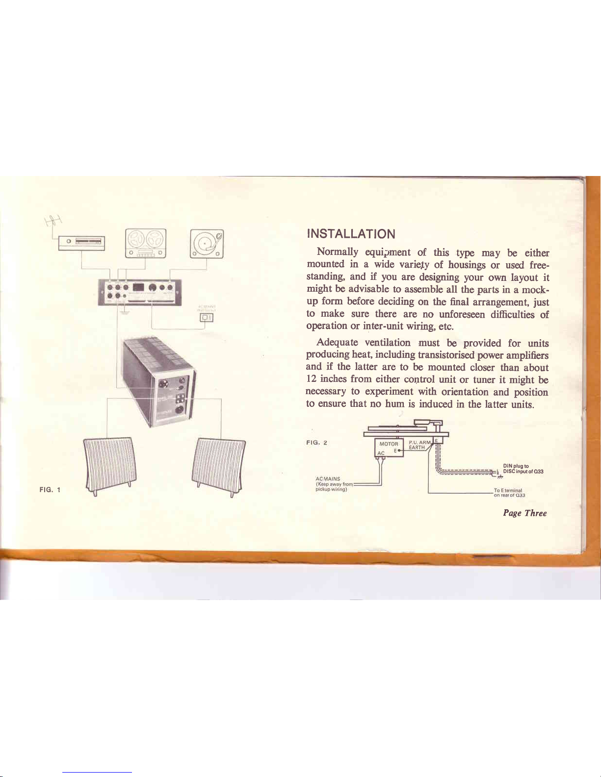
Hum canalsooccurif a low output magnetic
pickup
is too closeto a mainstransformer
or if its leads
run
closeto themainswiring.(See
Fig. 2).
All metal
parts
must
beearthedbut,because
multiple
earth connections
causehum, they shouldbe earthed,
directly or indirectly,by oneconnection
only, and the
wholeinstallationearthedat onepoint suchas the E
terminalon the rear of the control unit, OR the third
pin of thecontrolunit mainssocket,but not both.
(Note: All the Quad units are already bonded
together
by their own inter-connecting
cables).
Always
follow the
manufacturers'
instructions
supplied
with pickup, motor, taperecorder,
etc.,and refer any
query which may arise to your dealeror in caseof
difficultyto themanufacturer
concerned.
Page
Four
If the Quad 33 is not to be usedfree standingyou
will requirean aperturelA' x 3" as shownin Fig. 3
and a templateis providedin the rear of this booklet
to assistin marking thisout on thecabinet. Thecover
is then removedfrom the Quad 33, the unit p'assed
through the aperturefrom the front so that its lugs
locatein theaperture,andthecover
replaced
from the
rear,thusgrippingthecabinet
panelbetweentheQuad
33 front castingand its cover. The securing
screws
shouldbeinsertedfinger
tightand
then
given
one
further
half-turn to lock the unit firmly in position.
I' (2Omm)
tick
Lugs .OUAD 33cover
CovsrLocatins Slid6
FIG. 3
t)

The Quad 303 carries no controls and may be
mounted
out of sightinside
thecabinetor at anyother
convenient
positionin the installation.
The Quad 303may be eitherstoodon its feeton a
shelfor base
boardof a cabinet,
or moresecurely
fixed
by drilling four holesin theshelfor board to coincide
with thefeetcentres,
removing
thefeetsecuringscrews
and
passing
thelonger
screws
provided,
upthroughthese
holes, through the feet which act as spac€rs
to assist
circulation of air under the amplifier, and into the
tapped
bushesin thebase-plate.
Slotsor holes
shouldbe cut in or nearthe baseand
in or near the top of any enclosedcompartmentto
permit a flow of air upwards
throughthecompartment,
pastand throughtheamplifierto assistventilation. In
confined
spaces
wherethe exit ventsare not directly
over the amplifier a deflector plate of plywood or
asbestos
maybemountedat aninclined
angleabovethe
amplifierto helpguidetherisingwarm air towards
the
exit vent and prevent an accumulation
of warm air
underaclosed
horizontal
top.
Page Five

CONNECTIONS
Din styls plugs showing method of assembly. See individual illustrations
for Din connections.
ControlUnit to PowerAmplifier
Two leadsare supplied
with the control unit. That
with a 4-pin connectorat eachend is reversibleand
connectsthe control unit output to thepoweramplifier
input. The other connects
the switched
mains supply
from the control unit to the power amplifier and the
2-pin plug at the control unit end of this lead is
reversible.
(See
Fig. l0). Longer leadsare permissible
whererequiredfor special
installations
(see
Specification
onpage
2l).
Pape Six
Power
Amplifier
to Loudspeakers
Ordinary lighting flex or similar cablemay be used
for connecting
the loudspeakers
to thepoweramplifier
unless
averylongrunisinvolved
in which
case
aheavier
calibrecableshould
beused.As a roughguidetheDC
resistance
of the cableshouldnot exceed
about5,%
of
thenominalimpedance
of theloudspeaker.
Eachloud-
speaker
shouldbe connectedto its appropriate
llower
amplifieroutput sothat thetwo pairsof wires
arecon-
nectedin the sameway, to ensurethat the speakers
operatein phase.
For example,
if thetop outputsocket
on one channelis connected
to the left-handterminal
of its speaker,the top output socket on the other
channel should also be connectedto the left-hand
terminal of its speaker.This is quite straighfforward
but should there be any doubt the phasing can be
checked
later experimentally. (See
Page l5). Where
one loudspeaker
only is usedfor mono, phase
is not
important and in this case
eitheroutlet may be used
andthesocketsof theotherchannelleft vacant.
In cases
whereloudspeakers,
suchastheelectrostatic
loudspeaker, also require an eneryising supply, the
\

instructions
provided with the loudspeaker
should be
followed. Eachloudspeaker
should
becapable
of hand-
ling thefull output of the poweramplifier.
Notez Quad electrostaticloudspeakers
prior to serial
number16800
needslight modification
before
beingused
with the Quad 303amplifier.
Pickup
(Disc) Input
The pickup input is via a 5-pin plug and the same
connections
areusedfor all types
of pickup. The neces-
sary changein input circuitry to suit differenttypesof
pickup is achieved
by the Disc Adaptor Board. This
board providesmatching for pickups of low output
magnetic
types
(Ml), high output magnetic
types
(M2),
ceramic
types
(Cl), anda spare
position
(Sl), according
to theedge
inserted
into the holder. (See
Specification
on Page
20).
The M2 positionshould normally be usedfor most
magnetic
pickupsbut for those
with very low outputs
Ml should
beusedinstead.
The fourth position is to enable the amateur or
professional
engineer
to provideany other circuit con-
flguration
hemayrequire
and
it also
provides,
of course,
facility for accommodating
any new type of pickup
which may be introduced,
requiring a differentinput
from existing
types.
Page Seven
*6lril ru.*tgdr foebd,
FIG. 5

input and an AM tuner for long distance
reception
to
Radio 2. Quadself-powered
tunersare suppliedwith
the correctconnectors
andmay be plugged
in immedi-
ately. Theconnectors
used
onotherself-poweredtuners
should
beadaptedasn€cessary
andthosealreadyfitted
Rldb I fS.Qlt
t
uTcprRrcold
u'
,f,-,Sc
T,?t--
euAD
33
Sbrt AgfSG
FIG. 7
DISC ADAPTORBOARD
Radio (See
Fig.
7)
Socketsare providedon the Quad 33for two radio
tunersto be connected.
For example,
an FM tuner,
used
for monoor stereo,
maybe connected
to Radio I
PageEight

with thesame
typeof plugshouldbechecked
to ensure
that thesameconnections
areused.Theoutputof such
tunersshould be suitablefor the Quad 33 input of
l00mV and l0OK ohms (stereo) or l00mV and
50K
ohms
(mono).
The mains supply for thesetunersshould also be
takenfrom the mainsoutlet sockets
at the rear of the
Quad
33.(See
Fig.l0).
WARNING
On no accountshouldtheHT ILT lead
of earlier
Quadtuners
be connected to the power supplies socketsof the Quad 33
control unit. If such tuners are used a separutepower pack
must be provided.
Tape
Threeessential
functionsare provided
for tape
recording:
(l) to providea signal
of theright level
for recording,
not afiectedby any of the tone,filter or volume
controls
andwithout afiectingnormal listening;
(2) to accepta signal
of any likely level from the re-
corder for replay and subject this to all the
appropriatecontrolfacilities,and
FIG. 8 TAPE ADAPTOR BOARD
(3) to monitor thesignal
off thetape
duringrecording
without interruptingtherecordingoperation,
pro-
viding, of course,that the tape recorderhas a
monitoroutput.
PageNine

The plug-in Tape Adaptor Board provides three
alternativesignal
level
settings
each
for recordingand
replayon both channels,
by means
of small screws
inserted
from theundersideof theboard
intotheappro-
priatepositionfor thesignal
levelof thetape
recorder
to be used.(See
Fig.9 and Specification
on Pages
20
and2l').
Scr€wsfor adju$ing outpu!
lrcm Ou6d 33rotam r€coder
thecontrolunit to thecorresponding
pinsof thereplay
socket.Wherethe levels
andimpedancesaresuch
that
cross-talk
can appearin the cablesand connectors
it
will beadvisableto usecompletelyseparate
connections
for recordingandreplay.
MainsOutlets
Thesesocketsare intendedfor supplyingthe Quad
303
poweramplifierandtheFM stereo
tuner.Normally
it will be
moreconvenient
torunthemainssupply
direct
to tape recorderand gramophone
motor since these
incorporatetheir own on/off switching, but if other
units are run off the Quad 33 mainsoutlets the total
currentdrawn mustnot exceed
2 amps.
Mains
Input
A 3-pin connector
is provided for the control unit
and this shouldbe wired to the mainssupplyusinga
suitable
grade
of flexiblecable. In countries
wherean
earthconnection
is not usedor where
anexternal
earth
is connected
to the E terminal of the control unit the
third pin of theplugshould
beleft blank.
In$dthi6dgs
inlo r€arof
contol Untr
L6fthandchannol
Righ! hand channcl
FIG.9
Normallyeither
one
or bothtapesockets
maybeused
for recordingandreplayasconvenient
the(L) and (R)
pins
(See
Fig.7)of the
recordsocket
being
linkedinside
Pape Ten

Combined record/replay socket.
Any programme passing
through
the Quad 33 may be recorded
without
interrupting
normallisten-
Ing.
Two
switchedACMains
outlets
for supplying
radio
tunerand
power
amplifier
Input
forstereo/mono
radio Additional inout for
tape replayonly. ACMains
input.
IInput
forstereo,/mono
pickup.
Outputto power amplifier Plug-in printed circuit board
permitting independent adjust-
ment of signal levels for both
recording and replay on each
channel.
Eanhterminal.
All signal connections comply with the intemationally used DIN standads.
Second radio. e.9., AM for long
distancereception,
orAuxiliary
input.
Ftc. 10
Plug-in printed circuit board
canying pickup input circuit.
This board may be insertedon
any of itsfour edgesto provide
four
alternative
input
matchings.
Page Eleven
QIAD 33

Volumecontrol
and
on/off
switch QUADnameplatelightsup
when unit is
switched
on
Controlforadjusting
balancebetweenchannels
I
I
I
I
l
I
I
Pressto select
left-hand
channel
anduppertracktape.
Pressto select
right-handchan
nelandlowertracktape
Press both together for two
channelmono
Page Twelve
Pressingthe
Cancelbuttonover-
ridesthesettingsof bass,treble
andfiltercontrols
and
provides
a
veryuselul
reference
standard
Filter
Slopecontrol,used
in
con-
junction with the 5K, 7K and
10K pushbuttons,
removesre-
cord surface noise, high fre-
quency distortions,
eic (see
performance
curves)
FtG. t1
I
I
I
l
Press to select the input required
Pressing the Tape button while
another input is selected also
provides AB monitoring facility
off tap€ during recording: Press
to listen to tape: Release to
listen to original.

INITIAL
CHECKS
AND OPERATION
Beforeconnecting
the mainssupply,
ensure
that the
voltage
markedon therearof thecontrolunit and the
setting
of theselectors
on thepower
amplifier
andtuner
arecorrectfor your mains. Theseselectors
aresetby
withdrawing the cap $", rotating it to the required
voltageandpushing
it fully homeagain. Thenconnect
the mainsand rotate the volumecantrol to switchon
theequipment.The Quad33nameplate,
theQuad303
indicator
light andthetunerscale
should
nowlight up.
Pushbuttons (see
also
Filters)
The input (Radio 1, Radio 2, Tap, replayor Disc)
and the service
(Stereo,
or Mono on left-handspeaker,
right-handspeakeror both), are selected
by pressing
theappropriate
pushbuttons.
With Stereopressed,
all inputs are connected
for
stereo
reproduction.In thecaseof radio,thetunerwill
automaticallyswitchto Stereo
whena stereo
signalis
received,
reverting
to Mono at all othertimes.
Pressing either or both of the Mon buttons will
reproducea mono sigral from Disc or Radio I whether
tle programmesource
is mono or stereo.With Radio 2
or Tape inputs, however, apart from selectingloud-
speakers,
the Mon buttonsalso selectleft or righthand
inputs, each to its own speaker. In addition,* either
input maybereproducedoverboth speakers
by pressing
the Stereo button as well as the <-Mon or Mon'+
button and,of course,
Radio 2 or Tape.
* This facility wan not available prior to serial number 7500.
Volume Control
The volume control is advancedto the appropriate
level,bearing
in mind that apart from enablinga level
of sound
to be obtained
which suitsthe listeningcon-
ditionsof themoment,thevolume
controlalso
hasthe
importantfunctionof adjustingtheintensityof sound
so
that it is correctly related to the perspective of the
recordingor broadcast.
Thisisobviously
importantfor
realisticreproduction.
For example, if a voice is picked up close to a
microphone
in a very absorbentstudio,thenon repro-
Page Thirteen

ductionthat voicewill takeup a position
at thecentre
of, and in theplane
of theloudspeakers.
For natural
sound,therefore,
theloudspeakers
should
radiate
similar
power
tothatof the
originalvoice.If onthe
other
hand
thevoiceispicked
up somewayfrom themicrophone
in a morelive studio,thenthevoice
on reproduction
will takeup a position
somedistance
behindtheloud-
speakers
and it is clear that the powerrequired
for
natural
soundis nowverymuchless.Theposition
or
perspective
of the reproduced
soundis fixed at the
studio
endand thereis little that can be doneat the
listening
end to alter it. It follows that the volume
settingfor naturalsoundis to a largeextentfixedat
the
studioend.
Filters (See
page
16).
The
filters
affecttheextremeharmonicrange
onlyand
do not interfere
with musical
brilliance.
Theirpurpose
is to enablethe maximum
content
of theprogramme
to bereproducedwith theminimum
distortion.
With most typesof recording
the distortionrises
Pape
Fourteen
rapidly at high frequencies
and the wider the loud-
speakerrange
themore
audible
thiswill be. It maybe
removed
or mitigated
byrotating
thefilter
slope
control
anti-clockwise
from the
levelposition.
As thecontrol
is
rotated,
thequalityand " cleanness
" of thereproduc-
tion will improve. There will, however,
be a point
beyondwhich
furtherrotation
degrades
thesounddue
to loss
of theusefulharmonic
range.
The
pushbuttons
marked
5K,7K andl0K, determine
the frequency
at whichfilteringcommences
and that
marked
7K is the mostusefulfor modern
recordings.
Pressing
the5K pushbutton
transposes
thefilteropera-
tion to a lowerfrequency
for usewitholderrecordings
and pressing
the lOK pushbutton
transposes
it to a
higherfrequencywhere it is useful with very good
records
or highqualityradio transmissions.
TheCancel
buttonbypasses
thebass,
treble
andfilter
controlsto give a levelresponse.
This position
is a
reference
by whichtheeffects
of thesettings
of the
other
controlsmay be judged
withoutupsettingtheposition
of thesecontrols.

Balance
Control
This merely
adjusts
thebalanceof thetwo channels
andafter
initial adjustment
it should
requireno altera-
tionfor normal
listening
unless
amisbalanced
recording
or broadcast
is to be reproduced,
whichis unusual,
or
unlessthe position of the loudspeakers
or their
environment
ischanged.
Bass and Treble Controls (See
page
l6).
The musical
balance
of a programmeis carefully
adjusted
duringrecording
or broadcasting
andadjust-
mentof the
bass
andtreble
controls
should
notnormally
be
necessary
unlessaninferior loudspeaker
or thelisten-
ing environment
produces
some effect which needs
correction.
Once
set
for a particular
installation,
there-
fore.
thesecontrols
should
be
little
used.
Small
deviations
of the basscontrol will affectvery low notesonly.
Greater
deviations
aftectnot only the very low notes
to a greaterextent
but alsothe high bass
notes.The
treble
controlafiects
brilliance.
Loudspeaker
Phasing
If, for any reason,
there
is anydoubt
about
theway
in whichthe loudspeakers
areconnected
(see
page
6)
theirphasingmaynow bechecked
by playing
a mono
disc
over
bothchannels,
whenthesound
should
appear
to emanate
from a point midwaybetween
them. If
thisis indefinite
theconnections
to either
of theloud-
speakers,
but not both,should
be reversed.
Correctly
connected
thespeakers
will give
a definite
centresound
source
accompanied
by a morefull bodiedsound
in the
tenor
and
bass
registers.
Page Fifteen

Asthe Filterslope
control
is rotated lrom 0 to 25 the
filter swings from a level
response to a steep cut as shown.
f isthe
frequencyselected
bythe skHz.TkHz
or'10kHz
push
buttons.
ao&to&s@12"p
nt lA.
TheBass
STreblecontrols
provide
smoothandindependent
adjustment
of theresponse
to suit
programmeorenvironment
QUAD
33
PERFORMANCE
CURVES
All sub-audiosignalsbelow
20Hzaredrastically
filtered
as
shown.
Thethreecurues
correspond
to minimum,leveland
maximumsettings
olthe Bass
control.
s$ 16
Page Sixteen
/I
)
/7
t
ttl
,l

Loudspeaker
Position
Thestandard
of reproduction
obtained
from anyloud-
speaker
is influenced
by both its positionin the room
and its position in relation to the listening
area. The
optimumposition
canonly befound by experiment
and
this cannotbe carriedout quickly or in a perfunctory
manner,if long term non-fatiguinglisteningis to be
obtained.
It is a fact that thestandard
of reproduction
in many
homes,
bothmonoandstereo,
issignificantly
belowthat
whichcouldhave
beenobtained
hadsufficient
attention
been paid to loudspeaker
positioning. Broadly, for
stereo
the two loudspeakers
should
be 6ft' to 8ft. apart
with thelistener
atasimilardistance
from each.
Clearly,
when more than one personis listeningthey cannot
both occupy the sameposition and all listeningtests
shouldaim at obtaininggoodstereo
over a reasonable
area.
This can usuallybe achieved
over an areaimmedi
atelybehindthe listening
point alreadydefined'
with a
width equal to the distance
between
loudspeakers
and
with asimilar
depth.
Outside
this
area
the
overall
quality
shouldbe satisfactory
althoughtheperspectivemay be
degraded.
The measurement
of 6ft. to 8ft.is based
on
a smallroom. With a larger
room the scale
may be
increased
accordingly.
The quality of theresultsobtained
will depend
upon
thefollowing:-
(a) Theposition
of theloudspeakers
with respect
to
the room boundaries (and sometimesfloor
joists).
(b) Thedirection
of loudspeakeraxis.
(c) The position
of large
pieces
of furniture.
With stereo
thefollowing may be added:-
(d) The distance
apart.
(e) The point of intersectionof the loudspeaker
axes.
(f) The relation of the base line (an imaginary
straight line joining the two speakers)
to the
room boundaries.
(g) Theposition
of thelisteners.
The instructions
supplied
with the loudspeaker
may
resolvesome
of the
variables
andthe
rest
must
besolved
Page Seventeen

by experiment.Few people
can successfully
complete
these
experiments
at a singlesession
andit is strongly
recommended
thatthe
following
procedure
beadopted.
The loudspeaker(s)
should
be triedin thevarious
roompositions
whichappear
physically
possible,
in
orderto ascertain
whichpositions
are likely to be
worthfurtherinvestigation.
The loudspeaker
should
now be usedin each
of
these
positions
for normal
dayto daylistening.
The
usual attention
shouldbe paid to the programme
itself without any conscious
concentration
on the
quality. In thisway theoptimum
position
for most
satisfactorylistening
will soonbecomeapparent.
OPERATION
SUMMARY
With all the testsdetailed
in the previous
section
completed,operation
of the Quad33 should
now be
readily apparent
and completelystraightforward.
It
may
besummarised
asfollows:-
Use the pushbuttonsto selectinput and system
required.
Adjustthe
volume
control
for alevel
of soundsuit-
able
for theprogramme.
Page Eighteen
Adjustthefilterto obtain
the
best
quality
inherent
in the
programme
remembering
that
thismeansfilter-
ingaslittle as
possible.
Adjustbassandtreble
controlsonlyif it isneces-
saryto alterthemusical
balance
of the
programme.
Adjust the balancecontrol only if the programme
levelsof the two channels
are themselves
out of
balance.
SERVICE
Normally the dealersupplying
theequipment
will be
ableto assistwith adviceor anyattentionthe
equipment
may requirebut in caseof difficulty you should
return
any Quadunit you wishto have
checked,
direct to our
Service
Department,
or that of our.main agent
in the
countryconcerned,carriage
paidandpreferablypacked
in its originalcarton. If this is not available
a pack
will be
forwarded
onrequest.
Do notforgetto enclose
anotegivingyournameand
address,
full details
of thereasonfor returningthe unit
andall thesymptoms
you have
observed.

SPECIFICATION
DISTORIION:
RESIDUAL NOISE:
FREQUENCY RESPTONSE:
TONE CONIROIS:
FILTERSI:
INTER.CHANT\IEL
BALANCE:
BALANCE CONTROL
RANGE:
CROSSTALK:
FOR
QUAD
33 CONTROL
UNIT
All controls level, O'SVrms
output,
with anv inout.
Any coritrofsettings and any level
within overload ratings
0-30 phon weighting ls'7kHz bandwidth
controls level or cancel
o.o2%
)
) 30-lo,ooo
Hz
o.r'%
)
-90d8
Any input, any output
RIAA or flat as appropriate
:L ldB of published curves
(see
page 16)
To pubtished curvesat Sktlz,TkHzandl0kJlz! 3/o
(see
page16)
Within ldB with volume control varied
from maximum to -45db
9dB either way
Dependant on input sourceimpedances.
Reilav/record typically better 1an 70dB 30-10,000Hz
Intirchinnel tvrjiiattv better than 40dB 30-10,000 llz
: t0.5dB 30-20.000
Hz
Page Nineteen
Other manuals for 33
1
This manual suits for next models
1
Table of contents
Other QUAD Amplifier manuals

QUAD
QUAD 405 - annexe 1 User manual

QUAD
QUAD 606 User manual

QUAD
QUAD Vacuum Tuber Amplifier Systems II-FORTY User manual

QUAD
QUAD Elite Mono User manual

QUAD
QUAD VA-ONE+ User manual

QUAD
QUAD 99 Stereo Power Amplifier User manual

QUAD
QUAD VA-One User manual

QUAD
QUAD Platinum Series User manual

QUAD
QUAD 306 User manual

QUAD
QUAD Artera Stereo User manual