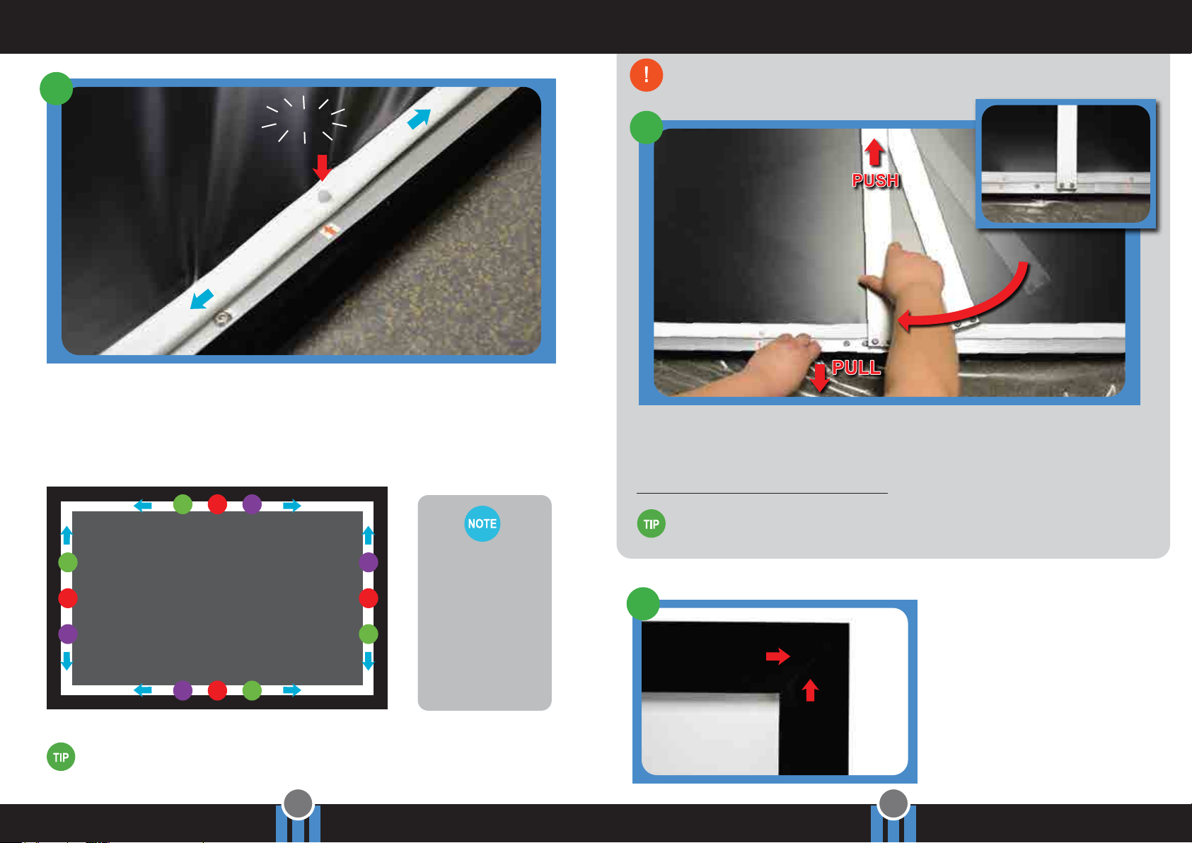
QualGear QG-PS-FF6-169-100-W User manual

11
Mount to the Wall
Slide the Hanging Brackets until they line up with
the secured mounting hardware. With an assistant, lift the
screen gently onto the secured Wall Mounting Screws so that
the keyholes on the Hanging Brackets fit over the screws.
18
INSTALLATION MANUAL
www.qualgear.com | 2 Year Limited Warranty | Version: December 2015
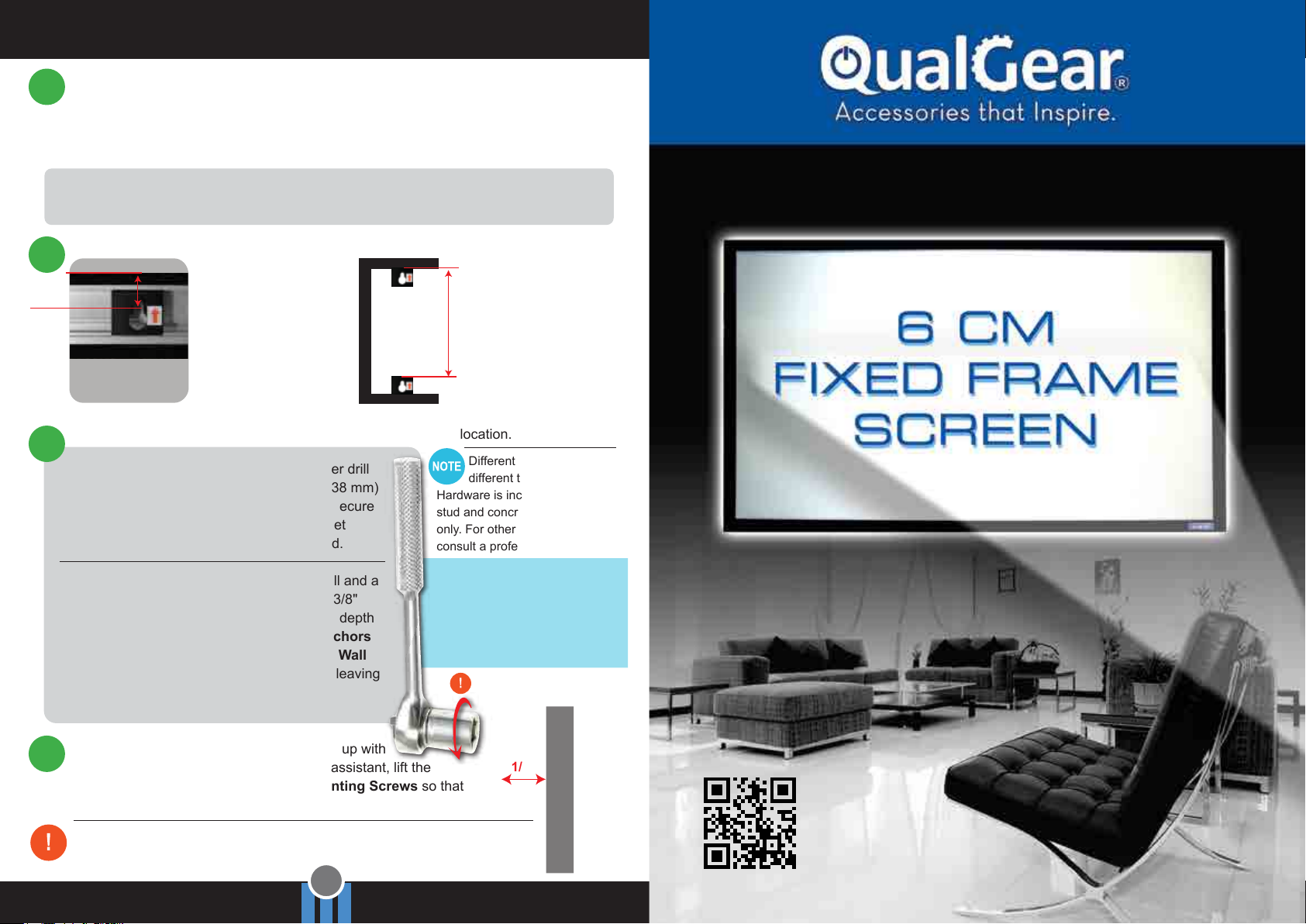
16 Top Hanging Brackets:
on the wall, measure
and mark 3/4" down
from the top edge of the
desired frame location.
IMPORTANT make sure
they are marked on the
center of the studs and
verify they are level.
Bottom Hanging
Brackets: measure and
record the distance from
the top of the bracket to
the top of the matching
bottom bracket on the
assembled frame. Mark
this distance on the wall
from the top marked
location.
approx. 3/4"
Record
Distance
17
Locate the Wooden Studs
This step applies to wooden stud wall installation only. Determine and mark the exact
locations of two stud centers on the wall. Wooden studs should be spaced so that the
weight of the screen is distributed evenly. In order to achieve this, mark the studs that
are separated by at least one-third to one-half of the projector screen’s total width.
15
For example: if the projector screen is 100" wide, look for two studs that are spaced
between 33" to 50" apart. Stud spacing 48" apart would be ideal in this case.
1/4"
IMPORTANT Verify that each Hanging Bracket is properly secured before releasing
the projector screen to avoid injuries and property damages.
Mark the Drill Locations for the Hanging Brackets
Different wall types require
different types of hardware.
Hardware is included for wooden
stud and concrete wall mounting
only. For other wall types, please
consult a professional.
Wooden Stud Wall Mounting: using a power drill
and 3/32" drill bit, drill pilot holes of 3/32" (2.38 mm)
diameter and approx. 1.18" (30 mm) depth. Secure
each Wall Mounting Screw by using a socket
wrench, leaving about 1/4" of thread exposed.
Concrete Wall Mounting: using a power drill and a
3/8" masonry drill bit, drill mounting holes of 3/8"
(10 mm) diameter and approx 1.18" (30 mm) depth
at the marked locations. Insert Concrete Anchors
and hammer them into the wall, secure each Wall
Mounting Screw by using a socket wrench, leaving
about 1/4" of thread exposed. Socket
Wrench
Do not use power drill to
fasten the Mounting Screws.
Use the anchors provided
for concrete wall mounting only.
Do not use them for drywall.
Also, use socket wrench for Wall
Mounting Screws to prevent
damages to the screw heads.

1 2
WARNING BEFORE YOU BEGIN THE INSTALLATION
• Please read this entire installation manual before you start installation and assembly.
• Remember that the assembly will require at least two people for some steps.
• Do not assemble in areas of high temperature to avoid damaging to the screen.
• The included mounting hardware may not be appropriate for all installation types, choose the
proper mounting hardware for your specific installation type.
• If you are not able to safely install the screen, consult a professional.
Wall Mounting Screws
& Concrete Anchors
(x4)
Fabric Tensioners
(number depends on screen size)
Hanging Brackets
(x4)
Frame Screws
(x24)
Allen Key
(x1)
Corner Joints
(x4)
Center Joints
(x2)
Support Bar
(x1)
Screen Fabric
(x1)
Frame Pieces
2 Vertical, 4 Horizontal
(x6)
Metal Rods
2 Vertical, 4 Horizontal
(x6)
PartsHardware
• Allen Key (Included) • Power Drill
• Level • Screwdriver
• Pencil • Socket Wrench
Required Tools
The parts and hardware
on this manual may vary
slightly from the actual parts
and hardware, but functionality
would be the same.

3 4
Preparation Connect the Horizontal Frame Pieces
3
Unwrap the Frame Pieces, and lay
them out carefully.
Then flip the Frame Pieces, so the metal
surface is facing upward.
The red arrows on the frames indicate
how many Fabric Tensioners to insert for
each Frame Piece. Repeat these steps
for all the Frame Pieces.
Line up the non-angled frame
ends of the Horizontal Frame
Pieces and slide the Center
Joint in the middle to connect
them.
Secure the Horizontal Frame Pieces
with the Frame Screws using the
Allen Key. Repeat these steps for the
other two Horizontal Frame Pieces.
Make sure that the assembly
area is clean and clear of debris
and sharp objects. At least two
feet of extra space is required
on all four sides when the
screen is spread out.
1
Unpack all the parts in the
box, but do not unroll the
Screen Fabric yet.
IMPORTANT
Hardware is stored in a
separate box. Do not discard
this box!
2
Allen Key
Frame Screw
Fabric Tensioner
Fabric Tensioner
Horizontal Frame
Vertical Frame
4
Center Joint
Horizontal Frame
5
Before connecting the corner Frame
Pieces, slide the Fabric Tensioners into
the track of the aluminum frame.
Place the Fabric Tensioners
The red arrow stickers specify
approximate locations of where
the Fabric Tensioners need
to be placed. Each arrow corresponds
to one opening on the screen fabric.
Hardware Box
Center Joint
QualGear logo is
on the bottom right
Frame Piece.

5 6
Place the Hanging Brackets Connect the Vertical and Horizontal Frame Pieces
Insert the Corner Joint
into the assembled
Horizontal Frame Pieces
and tighten with the Frame
Screws by using the Allen Key.
Tighten all the Frame
Screws to secure the corner
of the projector screen.
Repeat these steps until all
four corners are assembled
and secured.
Then, connect the secured
Horizontal Frame to the
Vertical Frame by inserting
the other end of the Corner
Joint.
Slide the two bottom
Hanging Brackets into the
track of the bottom frame.
Repeat these steps for the
top frame. The brackets
should be able to slide freely
along the frame track.
Hanging Brackets are used
to hang the projector screen
onto the wall.
There are four Hanging
Brackets for each projector
screen. Two go on the top
and two on the bottom frame
track.
Top Horizontal Frame
Bottom Horizontal Frame
Top
Bottom
Hanging Brackets
Tighten the screws
but do not over
tighten, adjustments can be
made later by loosening
the frame screws.
7
Vertical Frame
Horizontal Frame
6
Corner Joint
Red arrows on
the Hanging
Brackets always point
upward.

7 8
Connect the Metal Rods Insert the Metal Rods
There are four Metal Rods that need to be connected. Connect the male thread of the
metal rod to the female thread of the other. Repeat these steps for the other two Metal
Rods.
8
Make sure that the floor is clean and there are no sharp objects, then unroll the Screen
Fabric and place it gently on the floor with the viewing side facing down.
9
According to the length of
the Metal Rods, match
each rod to the correct side
of the Screen Fabric,
then carefully insert each
Metal Rod into the
Screen Fabric pocket.
After all four metal rods are
inserted, lay the Screen
Fabric onto the back of the
assembled frame.
10
11
Insert the rest of the Metal
Rods to the Screen Fabric
pockets located at the edge.
The longer metal
rods are for the
horizontal frame pieces
and shorter rods are for the
vertical frame pieces.
Metal Rod
Screen Fabric
Assembled Frame
Screen Fabric
Metal Rod
Do not force the Metal Rod as
it may exit the pocket and
damage the viewing area of
the screen.
WARNING

9 10
Install the Support BarAttach the Screen Fabric to the Frame
Line up each Fabric Tensioner with an arrow sticker. Begin with the center Fabric
Tensioner on each side of the frame. Once all the center Fabric Tensioners are secured,
then work towards each corner by snapping the Fabric Tensioners one at a time,
securing the Screen Fabric over each Fabric Tensioner along the way.
See the illustration below to determine the order of Fabric Tensioners to attach.
12
Snap!
WARNING If you are having difficulty getting the support bar in place, do not use
excessive force. Doing so may damage the projector screen.
Making Adjustments
If you notice any gaps at the frame
joints, first loosen the Frame Screws
on the back of the frame with the Allen
Key. While one person holds the
horizontal and vertical frame pieces
tightly together, the other person will
need to tighten the Frame Screws.
Repeat these steps until there is no
gap. Tighten the Frame Screws but do
not over tighten them.
14
A fair amount of tension is needed to pull the rods over each Fabric Tensioner. If
you are having difficulty with this step, try using a screwdriver as a lever to pull the
rod over each Fabric Tensioner, and be careful not to damage the Screen Fabric.
15 9
210 6
12
8
4
7
11
3
Screen Fabric is
designed to stretch.
Some force may
required to complete
this step. Once
finished, the Screen
Fabric should
be tight all around.
Support Bar provides extra support to the
center of the projector screen and prevents it
from sagging. To install the Support Bar,
it is best to work with an assistant.
13
Bottom Horizontal Frame
Installed
Support Bar
Center of the Frame
At the center of the frame, while one
person pulls the bottom of the screen, the
other person needs to push the Support
Bar up to the groove of the top horizontal
frame and slide it diagonally into the
groove of the bottom horizontal frame
until it is straight over the center of the
frame.
You may need to undo one or two fabric
tensioners to help slide the bar in place.
Center of the Frame
This manual suits for next models
1
Table of contents
Popular Projection Screen manuals by other brands

Elite Screens
Elite Screens Manual SRM Pro Series Quick user guide

Grandview
Grandview GRUC070V user manual

Elite Screens
Elite Screens IWB85SW2a user guide

Celexon
Celexon Ceiling Recessed Electric Professional Plus operating instructions

FP
FP PostBase Vision Quick reference guide

EPV
EPV Marquee Tension Series installation guide

Panasonic
Panasonic PT-40LC12-K operating instructions

Elite Screens
Elite Screens Evanesce B Series user guide

Da-Lite
Da-Lite Boardroom ElEctrol Instruction book

Rehau
Rehau RELAZZO Assembly instructions

Draper
Draper Signature E Series Installation & operating instructions

Celexon
Celexon Motor Green Screen manual