Quantum Composers Jewel Laser User manual

Jewel Laser Manual v1.6 Page 1
Jewel Laser Operating Manual
QUANTUMCOMPOSERS,INC
PO Box 4248
Bozeman, MT 59772
(406)582-0227phone
(406)582-0237fax
www.quantumcomposers.com

Page 2 Jewel Manual v1.6 | Quantum Composers
CONTENTS
1. INTRODUCTION..............................................................................................................................................4
2. SAFETY ...........................................................................................................................................................5
LASER SAFETY.......................................................................................................................................................6
ELECTRICAL SAFETY...............................................................................................................................................7
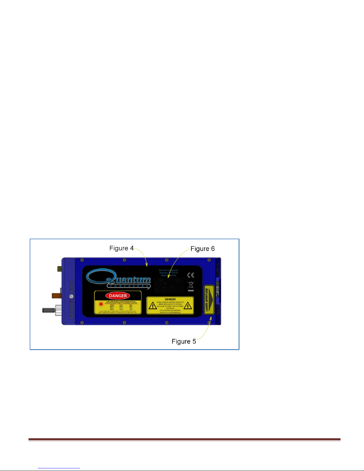
Safety Labels and Locations............................................................................................................................8
3. SYSTEM OVERVIEW....................................................................................................................................11
JEWEL LASER BLOCK DIAGRAM.........................................................................................................................11
Jewel Power Adapter.....................................................................................................................................11
JEWEL LASER DESCRIPTION .........................................................................................................................12
LASER FEATURES .......................................................................................................................................12
4. JEWEL LASER SETUP.................................................................................................................................14
UNPACKING LASER .........................................................................................................................................14
System Inventory............................................................................................................................................14
SYSTEM SETUP ....................................................................................................................................................15
COMMUNICATION -USB........................................................................................................................................15
Driver Installation (Windows XP)....................................................................................................................15
Driver Installation (Windows 7).......................................................................................................................16
5. JEWEL LASER APPLICATION....................................................................................................................17
JEWEL LASER APPLICATION OVERVIEW .................................................................................................................17
Getting Started ...............................................................................................................................................17
LASER OPERATION CONTROL...................................................................................................................18
6. LASER OPERATION.....................................................................................................................................20
MANUAL SHUTTER OPERATION................................................................................................................20
Laser head connectors...................................................................................................................................21
Laser status connectors .................................................................................................................................22
INITIAL POWER ON ......................................................................................................................................22
POWER OFF..................................................................................................................................................22
7. DEVICE COMMANDS ...................................................................................................................................23
COMMAND TYPES.................................................................................................................................................23
8. MAINTENANCE.............................................................................................................................................29
SERVICE PROCEDURES.........................................................................................................................................29
9. TROUBLE-SHOOTING..................................................................................................................................30
No Laser Output.............................................................................................................................................30
Energy is Low.................................................................................................................................................30
10. SPECIFICATIONS .........................................................................................................................................31
11. CABLES AND CONNECTION PINOUT........................................................................................................32
12. MECHANICAL INTERFACE DRAWINGS ....................................................................................................33
13. CUSTOMER SERVICE..................................................................................................................................36
WARRANTY ..........................................................................................................................................................36
FEEDBACK............................................................................................................................................................36

Jewel Manual v1.6 | Quantum Composers Page 3
14. APPENDIX A - DICHROIC MODULE............................................................................................................37
OVERVIEW ...........................................................................................................................................................37
CONFIGURATIONS.................................................................................................................................................37
SPECIFICATIONS...................................................................................................................................................37

Page 4 Jewel Manual v1.6 | Quantum Composers
This manual contains the information necessary to operate and maintain the Quantum
Composers Jewel Laser. It provides information for setup and installation, operation, service,
preventive maintenance, and troubleshooting (fault isolation). Generally,eachtopichasitsown
sectionand nosectionassumesknowledge of information from other sections.
This laser is truly “turn-key” and has been shipped fully functional. Only minor adjustments are
necessary after installation. The connections are sized, keyed or labeled to increase the
simplicity of installation.
Technical Support
Forquestionsor commentsaboutoperatingtheJewel LasertheQuantumComposers technical
staffcan bereachedviaone of thefollowingmethods:
Phone - (406) 582-0227
Fax - (406) 582-0237
Internet-www.quantumcomposers.com
Warranty
The Jewel Laserhasa one-yearlimited warrantyfromthedateofdelivery. Thiswarrantycovers
defects inmaterialsand workmanship. QuantumComposerswillrepairorreplaceanydefective
unit. ContacttheQuantumComposersServiceDept.forinformationonobtainingwarrantyservice.
Package Contents
Theboxyoureceiveshouldcontainthefollowing:
Jewel Laser
Safety Key
Shorting Jumper (Ext Intlk / Rmt Itlk)
Power Supply, with AC Power Cord
User’s Manual andControlSoftwareon Disk
Contact Quantum Composers (406)582-0227if anypartsaremissing.
1. INTRODUCTION

Jewel Manual v1.6 | Quantum Composers Page 5
This product complies with safety standards EN61010:1993+A2:1995,
EN60825:1994+A11:1996, and CDRH21 CFR 1040.10(d). Do not install substitute parts or
perform any unauthorized modification to this product. Return the product to manufacturer
for service or repair to ensure that all safety features are maintained.
Do not operate this product beyond its specifications.
Caution labels, in accordance with CDRH and CE requirements, are
prominently displayed on the Laser Optical Assembly and Laser Power
Supply. The maximum ratings indicated on the system labels are in
excess of the normal operating parameters. Please refer to the Data
Summary Sheet for specific information pertaining to your system.
The laser produces laser radiation, which is hazardous to eyes and skin, can
cause burning and fires and can vaporize substances. This chapter contains
essential information and user guidance about these hazards.
SYMBOL
DEFINITION OF SYMBOL
CAUTION: Calls attention to a procedure, practice, or condition that could cause damage to
the product, or cause bodily injury to the user. Refer to accompanying documentation.
ATTENTION: Ce symbole signale une procédure, une méthode ou une condition qui peut
endommager le produit ou blesser l’utilisateur. Se référer à la documentation jointe.
ACHTUNG!: Beachten Sie Verfahren, Praktiken oder Zustände, die das Produkt
beschädigen oder zu Verletzungen fuhren können. Lesen Sie die deigefugte Dokumentation.
ATTENZIONE: Porre estrema cautela alla procedura, uso o condizioni che potrebbero
danneggiare il prodotto o l’utilizzatore. Far riferimento alla documentazione inviata insieme al
prodotto.
ADVERTENCIA: Llama la atención sobre un procedimiento, práctica, o condiciόn que podría
causar daño al producto o puede herir al usario. Consulte la documentaciόn que acompaña.
CAUTION: Risk of Electric Shock.
ATTENTION: Risque d’éléctrocution.
ACHTUNG!: Gefahr durch Stromschlag.
ATTENZIONE: Rischio di shock elettrico.
ADVERTENCIA: Riesgo de choque eléctrico
2. SAFETY

Page 6 Jewel Manual v1.6 | Quantum Composers
CAUTION: Risk of exposure to hazardous laser radiation.
ATTENTION: Risque d’exposition à un rayonnement laser dangereux.
ACHTUNG!: Gefahr durch gefährliche Laserstrahlung.
ATTENZIONE: Rischio di esposizione a pericolose radiazioni laser.
ADVERTENCIA: Riesgo de exposición a la radiaciόn peligrosa del láser.
LASER SAFETY
VISIBLE AND/OR INVISIBLE LASER RADIATION
CAUTION: The Jewel Laser is a Class 4 OEM laser. Its output beam is, by
definition, a safety and fire hazard. Precautions must be taken to prevent
accidental exposure to both direct and reflected beams.
Precautions for Safe Operation of Class 4 OEM Lasers:
DO NOT remove the protective covers from the Laser Head. No user serviceable
components are inside. Exposure to laser radiation when covers removed.
Avoid looking directly at the laser output beam.
Do not wear reflective jewelry while using the laser, as it might cause inadvertent
hazardous reflections.
Use protective eyewear at all times. Consult the ANSI, ACGIH, or OSHA standards listed
at the end of this section for guidance on goggles and safety matters.
Operate the laser at the lowest possible beam intensity, given the requirements of the
intended application.
Increase the beam diameter wherever possible to reduce beam intensity and thus reduce
the hazard.
Avoid blocking the laser beam with any part of the body.
Use an IR detector or energy detector to verify that the laser beam is off, before working in
front of the laser.
Establish a controlled access area for laser operation. Limit access to those trained in the
principles of laser safety.
Maintain a high ambient light level in the laser operation area so the eye pupil remains
constricted, thus reducing the possibility of hazardous exposure.
Post prominent warning signs near the laser operation area.
Provide enclosures for the beam path whenever possible.
Set up an energy absorber to capture the laser beam, preventing unnecessary reflections
or scattering.

Jewel Manual v1.6 | Quantum Composers Page 7
CAUTION: Use of controls, adjustments or performance of procedures other
than those specified in this Operation Manual may result in hazardous
radiation exposure.
Follow the instructions within this manual carefully to ensure the safe operation of your
laser. At all times during laser operation, maintenance, or servicing, avoid unnecessary
exposure to laser or collateral radiation that exceeds the accessible emission limits listed in
"Performance Standards for Laser Products," United States Code of Federal Regulations,
21 CFR 1040.10(d). This information is also available in EN60825-1:1994, Section 8.2,
titled “Measurements of Laser Radiation for Determining Classification.”
Preventative Maintenance for Safety: Preventative maintenance is required to ensure the
laser remains in compliance with Center for Devices and Radiological Health (CDRH)
Regulations and European Norm (EN) requirements. This laser product complies with Title
21 of the United States Code of Federal Regulations, Chapter 1, Subchapter J, Parts
1040.10, as applicable, and with EN60825-1:1994, Part 1 for a Class 4 laser, as applicable.
To maintain compliance, verify the operation of all features listed below, either annually or
whenever the product has been subjected to adverse environmental conditions, which may
have affected these features and functions.
oVerify that removing the remote interlock connector prevents laser operation. This
connector is located on the end cap of the laser.
oVerify that the laser will operate only with the key switch in the ON position and the
key can only be removed when the switch is in the OFF position.
oVerify that a time delay exists between turning on the Key Switch and the start of
laser firing. The time delay must be long enough to allow action to be taken to avoid
exposure to laser radiation.
Please follow all local jurisdictional safety requirements for your area.
ELECTRICAL SAFETY
CAUTION: Both the Laser Optics Assembly and Laser Power Supply contain
electrical circuits operating at lethal voltage and current levels. Always
unplug the system Mains connection and wait at least one (1) minute to allow
capacitors to discharge before servicing any part of the laser system.
Consult with the Quantum Composers if repair of the laser electronics is required. Only those
trained in high voltage, high current electronics, and who understand the laser circuitry, should be
allowed to service and repair the laser electronics. If any such action is required, it is
recommended that you contact the Quantum Composers for details.
Sources of Laser Safety Standards
"Safe Use of Lasers" (Z136.1)
American National Standards Institute (ANSI)
11th West 42nd Street
New York, NY 10036 USA
Phone: (212) 642-4900

Page 8 Jewel Manual v1.6 | Quantum Composers
"A Guide for Control of Laser Hazards"
American Conference of Governmental and Industrial Hygienists (ACGIH)
6500 Glenway Avenue, Bldg. D-7
Cincinnati, OH 45211 USA
Phone: (513) 661-7881
Occupational Safety and Health Administration
U.S. Department of Labor
200 Constitution Avenue N.W.
Washington, DC 20210 USA
Phone: (202) 523-8148
“Safety of Laser Products” (EN60825-1:1994)
Global Engineering Documents
15 Iverness Way East
Englewood, CO 80112-5704 USA
Phone: (303) 792-2181
SAFETY LABELS AND LOCATIONS
Figure 1 and Figure 2 show the safety, model number, serial number and origination
labels, and their locations on the Jewel Laser. These labels are installed at the factory and
should not be removed by the user. If for some reason a label is removed, obscured, or
damaged in any way, please contact the manufacturer for a replacement.
Figure 1: Safety Labels - Jewel 1064nm ONLY

Jewel Manual v1.6 | Quantum Composers Page 9
Figure 2: Safety Labels - Jewel 1064, 532, 355, 266nm
Figure 3 Safety Labels - Jewel 532nm OR 355nm OR 266nm ONLY
Figure 4 Energy & Cover Label
Figure 5 Laser Aperture Label

Page 10 Jewel Manual v1.6 | Quantum Composers
Figure 6 Model, Serial Number & Date of Mfg
Figure 7 Cover Removed

Jewel Manual v1.6 | Quantum Composers Page 11
JEWEL LASER BLOCK DIAGRAM
Figure 8 shows the laser system block diagram, which consists of the Jewel Laser, a personal
computer, and a power supply.
Figure 8 - System Block Diagram
JEWEL POWER ADAPTER
The power adapter for the Jewel Laser is a typical laptop style power adapter. It accepts inputs of
100-240 VAC and 50-60 Hz, and outputs 36 VDC, 1.6A (See Figure 9).
Figure 9 Power Supply
3. SYSTEM OVERVIEW

Page 12 Jewel Manual v1.6 | Quantum Composers
JEWEL LASER DESCRIPTION
The Jewel is a conductively-cooled 1064/532/355/266nm diode pump laser with output energy
pulses up to 15mJ and rep rates up to 20Hz. It is a self-contained laser head, including the diode
and Q-switch drivers.
LASER FEATURES
The laser features (Figure 10 and Figure 11) are indicated below.
Figure 10 Jewel Connection Panel

Jewel Manual v1.6 | Quantum Composers Page 13
Figure 11 - Laser Features
1. The laser resonator is a highly efficient diode pumped laser (20Hz less than 5W) with a
fundamental output wavelength of 1064nm. The monolithic structure is machined from a
single block of stress-relieved aircraft grade aluminum. Resonator mirrors are hard-
mounted to the machined resonator bench resulting in an extremely stiff, rugged resonator
which is much less sensitive to misalignment then other laser resonators.
2. Systems w/ output harmonics, 532/355/266nm, have an attached nonlinear optics module
(NLO). The 1064nm output of the laser enters the integral nonlinear module. Harmonic
generation is performed using non-linear crystal(s). The crystal temperature is tightly
regulated by mounting the crystals inside a temperature controlled oven assembly. The
output is collinear, with all wavelengths exiting the same aperture.
3. An optional dichroic module can be attached to “scrape” residual wavelengths from the
output beams allowing single wavelength output.

Page 14 Jewel Manual v1.6 | Quantum Composers
UNPACKING LASER
The laser has been carefully packaged for shipment. If the container arrives damaged in any way,
please contact the shipper's agent to be present for the unpacking. Inspect each unit as it is
unpacked, looking for dents, scratches, or other damage. If damage is evident, immediately file a
claim against the carrier and notify the manufacturer.
It is recommended that the shipping container be kept, for possible shipping, should the unit
require repair or maintenance services. If a damage claim has been filed, the container will be
needed, to prove shipping damage.
The laser is a turnkey system, designed so that a field service engineer is not required to get the
system up and operating properly. The system has undergone extensive testing to verify its
conformance to the specifications, prior to delivery.
Before operating the laser, however, it is important to fully understand its main features and
controls.
CAUTION: Do not power up the system before thoroughly reading the
system description. Use of the controls or adjustments, or performance of
procedures other than those specified in this user’s manual my result in
hazardous radiation exposure, laser system damage or result in voiding
the warranty. Please do not connect the main power until you verify the
power switch is in the OFF position.
SYSTEM INVENTORY
The Jewel Laser consists of the following items. Verify that all listed items are present in the
shipping container. If there are any shortages or discrepancies, contact Quantum Composers
immediately.
Jewel Laser
Safety Key
Shorting Jumper (External Intlk / Rmt Intlk)
Power Supply with Power Cord
User’s Manual andControlSoftwareon Disk
Acceptance Test Results
4. JEWEL LASER SETUP

Jewel Manual v1.6 | Quantum Composers Page 15
SYSTEM SETUP
CAUTION: When utilizing the Remote Interlock capability, use an isolated contact
closure such as a relay to avoid generating undesirable ground loops.
CAUTION: Ensure that the system is connected to the proper Mains voltage. The
voltage rating is marked on the Laser Power Supply. Operating the system at the
incorrect voltage may result in damage to the unit.
CAUTION: Ensure that the Mains power outlet, that the Laser Power Supply
connects to, is properly grounded. Poor ground quality could result in exposure
to electrical shock.
Set up laser beam line, with appropriate optics and/or beam dump(s).
Set up remote interlock, as needed.
Mount Jewel laser to an appropriate, heat sinking surface.
oApply thermal material between the unit’s bottom, mid-section and the mounting
surface of the heat sink.
DO NOT apply thermal material to mounting feet or alignment pins.
Note: The Jewel will operate without a heat sink, but its duty cycle will be
greatly reduced.
oThe heat sink must dissipate 4 watts, at a maximum of 35oC, on the bottom surface
of the laser head (See Interface Drawings).
Attach a USB cable from the port of the computer to the port on the Laser Endcap.
Attach Power Supply DC cord to the Jewel laser head.
Attach Power Supply AC cord to a proper Mains outlet.
COMMUNICATION - USB
The Jewel laser provides a standard USB connection for remote communications. When the
Jewel is connected to a remote computer via the USB connection, the computer will recognize the
unit as a “QC-LASER”. Drivers will need to be installed for the remote computer to interface to the
Jewel laser. Drivers are included on the provided CD. Once the drivers have been installed, the
Jewel laser will show up in the Device Manager as a USB to Serial Port Adapter. The Jewel laser
can then be communicated with by either the included Jewel Laser application, or by using any
generic communication terminal program. The unit is baud rate independent, so any speed can be
selected. Typically a rate of 115,200bps can be used.
DRIVER INSTALLATION (WINDOWS XP)
1. Plug the Jewel into the computer using a USB cable. Make sure the unit is powered on.
2. The computer will display a message indicating it has found new hardware: “QC-LASER”.
3. The new hardware wizard will launch. Check the “Install from a list or specific location”
option and click next.

Page 16 Jewel Manual v1.6 | Quantum Composers
4. Select “Search for the best driver in these locations” and check the option to “Include this
location in the search”. Click the browse button and locate the folder on the CD where the
Jewel drivers are located. Click next.
5. A message window will launch asking if you want to continue installing this driver. Select
the “Continue Anyway” button.
6. It should now indicate that it is installing a driver for a “QC-LASER USB Communications
Port”.
7. Once the process is finished, a message will indicate that the drivers have been
successfully installed.
8. You can now communicate with the Jewel using either the included Jewel application or by
using any generic communication terminal program. You can view the Com Port number
assigned to the Jewel in your computers device manager under Ports.
DRIVER INSTALLATION (WINDOWS 7)
1. Plug the Jewel into the computer using a USB cable. Make sure the unit is powered on.
2. A message will pop up on the computer indicating it has found new hardware and is
installing device driver software.
3. A message will indicate that the device drivers have not been successfully installed. The
Action Center may then launch with a list of options. Close the Action Center and do not
launch any of the actions.
4. Go to your computers Device Manager. This can be done by one of two ways. a) Right
click on the desktop “Computer” icon and select properties. Select Device Manager on the
left toolbar. b) Navigate to Control Panel and then Device Manager.
5. In Device Manager you should see a device under the Other Devices called the QC-
LASER. There will be a yellow exclamation point next to it.
6. Right click on the QC-LASER and select update driver software.
7. Select “Browse My Computer” for driver software and browse to the location of the USB
drivers for the Jewel. The location is typically found on the software CD. It will contain a file
called “Jewelcdc.inf”. Select the folder in which the file resides, not the file itself. Click next.
8. Windows will then indicate a warning window that the drivers are not verified. Select “Install
this driver software anyway”.
9. A message will then indicate that the drivers have been successfully updated and a QC-
LASER USB Communication Port is now available.
10.You can now communicate with the Jewel using either the included Jewel Laser application
or by using any generic communication terminal program. You can view the Com Port
number assigned to the Jewel in your computers device manager under Ports.

Jewel Manual v1.6 | Quantum Composers Page 17
JEWEL LASER APPLICATION OVERVIEW
The Jewel can easily be interfaced by means of the included Jewel application. On standard
models, a USB cable and a port with USB 1.1 capabilities or greater ( 2.0 or greater
recommended) are required to communicate with the unit. If the equipment is used in a manner
not specified by the manufacturer, the protection provided by the equipment may be impaired.
GETTING STARTED
Attach a USB cable from the port of the computer to the port on the Laser Endcap.
Power up the Jewel laser head.
Start the Jewel software.
The Jewel Laser application startup screen will be displayed as shown in Figure 12.
oThis application has been designed as a graphical user interface for ease of use. It
includes a Command Terminal section that can be used to manually send and
receive commands, to and from the laser system.
oThe software allows you to control the basic functions of the laser. The user can
pick energy level, firing mode, and frequency.
oThe software provides a system status indicator for the major interlocks and faults.
Note –A fault will require the laser to be disabled. User must determine cause of
fault, deal with it appropriately, and re-enable laser to Fire.
oThe System Information section displays the Jewel serial number as well as
firmware and gate array versions.
Select and enter control parameters on the Jewel software panel.
Enable and Fire.
oNote: See below for detailed information on laser operation.
5. JEWEL LASER APPLICATION

Page 18 Jewel Manual v1.6 | Quantum Composers
Figure 12 Jewel Software Application Main Window
LASER OPERATION CONTROL
The user is responsible for ensuring a suitable beam path and appropriate beam dumps are
provided, before firing the laser.
1. Pulse Mode –Options are continuous, single shot or burst.
a. Continuous mode –The laser will fire continuously from the time the Fire button is
pressed until the Stop button is pressed. The pulses per second are controlled with
the Rep Rate parameter, under System Settings.
b. Single Shot –The laser will output 1 single laser pulse when the Fire button is
pressed.
c. Burst mode - The laser will output the number of laser pulses specified by the Burst
Count parameter, under System Settings. The laser will stop firing at the end of the
burst.
2. Diode Current –Current, in Amps, per pulse sent to the laser diode. See the system ATP
document for the optimal value.
a. System alignment should typically be done at diode current levels 10 to 20 Amps
below the optimum setting.
3. Diode Pulse Width –In µsec it is the width of the diode current pulse. See the system ATP
document for the optimal value.

Jewel Manual v1.6 | Quantum Composers Page 19
4. Diode Trigger- The diode can be internally or externally triggered. Default is internal
trigger.
5. Qswitch Enable –This box must be checked for normal operation. When not selected, the
qswitch will not function preventing output from the laser head.
6. Qswitch Delay –In µsec it is the delay from the start of the diode pulse. See the system
ATP document for the optimal value.
7. Qswitch Trigger –The Qswitch can be internally or externally triggered. Default is internal
trigger.
8. Wait Count –This setting is in pulses and represents the number of diode pulses before the
qswitch is triggered. For example, a setting of 3 would pulse the diode 3 times the qswitch
would function on the 4th diode pulse. This parameter is applied to all Pulse Modes.
9. Divide By N –This parameter will set the qswitch to function on every XX diode pulse. For
example, a divide by value of 2 will trigger the qswitch on every 2nd, 4th, 6th… diode pulse.
10.Fire button –Selecting the fire button will start laser output. NOTE: the laser must be
enabled before the Fire button becomes active.

Page 20 Jewel Manual v1.6 | Quantum Composers
The laser has undergone extensive testing to verify its conformance to the specifications prior to
delivery.
Once the laser has been set up as outlined in the previous chapter, it is ready to operate. Turn
the Key Switch ON. After approximately 10 seconds the laser is initialized and ready for operator
control. See summary Data Sheets included with our laser for factory preset operating
parameters.
CAUTION: Below is a list of guidelines, which apply to all Quantum Composers’
laser systems. These guidelines should be followed whenever possible, to avoid
laser damage.
Operate the laser in a dust-free environment, and keep the Laser Optics covered when not
in use. This protects the output aperture against dust and particulate.
The Laser Optics Assembly is sealed with careful attention to use of low outgassing
materials. Silicone and similar sealing, bonding or insulating materials should not be used
in close proximity to the Laser Optics because these substances will outgas, and could
contaminate the output window, causing laser damage.
Avoid back reflections. Back reflections of even a small percentage of the output energy
can promote damage to optical components in the Laser Head. For example, an uncoated
convex lens or a glass disk calorimeter will reflect about 4% of the incident energy. While
the reflection may seem harmless, it can perturb the resonator operation to the extent that
the near field beam intensity profile is degraded, and may promote optical damage. It may
also affect the resonator hold-off, which can cause prelasing and catastrophic optical
damage. In some cases, even anti-reflection coated glass optics can reflect enough
energy to promote damage to laser optics. It is best to use only quality optics coated for
the operating wavelength.
CAUTION: To avoid laser damage, minimize back reflections of the output beam.
When reflections are unavoidable, direct them away from the optical axis of the
system by canting the optics off-axis. Failure to do so can cause laser damage and
void the warranty.
MANUAL SHUTTER OPERATION
The Jewel Laser utilizes a manual shutter, located at the output of the laser head (see Figure 13).
The shutter blocks laser output when in the CLOSED position. An internal switch prevents the
laser from firing. The switch is satisfied only when the lever is fully in the OPEN position.
6. LASER OPERATION
Table of contents
Other Quantum Composers Measuring Instrument manuals
Popular Measuring Instrument manuals by other brands

TPS
TPS WP-81T manual

Omntec
Omntec Proteus Series System programming manual

Endress+Hauser
Endress+Hauser Deltabar PMD75B HART manual

Heathkit
Heathkit HM-2140 manual

Dwyer Instruments
Dwyer Instruments SAH-22-IN Installation and operating instructions

Dickey-John
Dickey-John Seed Manager SE Operator's manual

Mastech
Mastech MS5901 user manual

STS Instruments
STS Instruments Siloxane manual

PCE Instruments
PCE Instruments PCE-N24 Series user manual

Elsner
Elsner KNX TH65-AP Technical specifications and installation instructions

Druck
Druck LR-Cal TLDMM 2.0 Series operating manual

Shodex
Shodex IC SI-35 4D Operation manual