Quantum Composers 9730 Series User manual

9730 Series
Digital Delay Current Generators
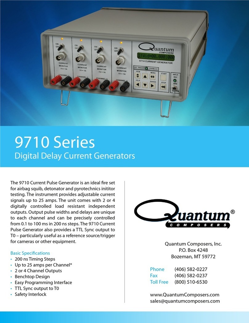
Our most capable current generator, the 9730 series
provides users with the ability to generate highly
precise current pulses, making this unit ideal for appli-
cations that require a high level of accuracy and
repeatability. Advanced safety features provide user
assurance.
Basic Specications
• 200 ns Timing Resolution
•2 or 4 Channel Outputs
•6 Amps Per Channel
•Easy Programming Interface
•Integrated Bridgewire Resistance Measurement
•Safety Interlocks and Keyed Front Panel Interface
Quantum Composers, Inc.
P.O. Box 4248
Bozeman, MT 59772
Phone (406) 582-0227
Fax (406) 582-0237
Toll Free (800) 510-6530
www.QuantumComposers.com
sales@quantumcomposers.com

Toll Free (800) 510-6530
Fax (406) 582-0237 Email info@quantumcomposers.com
Web www.QuantumComposers.com
Product Information
The Model 9730 Series is designed for airbag and
pyrotechnic initiator testing and represents the latest in
current pulse generating capabilities with compelling
features that provide users with time-saving characteristics
of adjustability, simple operation and programmability. The
9730 comes in a 19” 2U form factor as a 2 or 4 channel
model with current sensing and resistance measurement
capabilities. This unit is ideal for applications that require a
high level of accuracy and repeatability.
High functionality, safety, and a rapid
return-on-investment are the hallmarks of this new reset
for pyrotechnic initiators. The Model 9730 provides
multiple ring channels: all-re, no-re, resistance
measurement, DC current, capacitor discharge, Bruceton,
Neyer, and high current.The performance and advanced
features of the 9730 current pulse generator make it ideal
for applications such as air bag deployment testing (squib
detonation) or igniter deployment that can be done
reliably, safely and with repeatability.
Standard Features
• Up to 4 individual outputs with fully individual programming
and control.
• Up to 6A output per channel.
• Front and rear external trigger inputs.
• Current monitor – The current output from the unit is monitored and a
voltage representation the waveform is presented at a front panel BNC
connector.
• Voltage monitor- The voltage across the load being driven is monitored
and a voltage representation is present at a front panel BNC connector.
*Instantaneous power and total energy may be derived with the aid of
both the current and voltage monitors.
• SAFETY - Keyed front panel re enable, mechanical and software
interlocks.
• Complete channel and system setup stored in memory. Provides
12 memory storage slots.
• Meets Bruceton and Neyer requirements
• Analog signals depicting current and voltage
Advanced Features/Options
• Integrated 4-wire resistance measurement for each channel with pre and post testing features. Ability to set the mean and
upper/lower limits to determine what construes a resistance fault
• Current and voltage monitor outputs.
• Front and rear sync outputs.
• Safety features include remote interlock, removable keyed enable switch and internal error checking.
• RS232, USB, and optional Ethernet computer programming interfaces
SPECIFICATIONS 9730 Series
Toll Free (800) 510-6530
Fax (406) 582-0237
Email info@quantumcomposers.com
Web www.QuantumComposers.com
Standard Features
• Up to 4 individual outputs with fully individual programming
and control.
• Up to 6A output per channel.
• Front and rear external trigger inputs.
• Current monitor – The current output from the unit is monitored and a
voltage representation the waveform is presented at a front panel BNC
connector.
• Voltage monitor- The voltage across the load being driven is monitored
and a voltage representation is present at a front panel BNC connector.
*Instantaneous power and total energy may be derived with the aid of
both the current and voltage monitors.
• SAFETY - Keyed front panel re enable, mechanical and software
interlocks.
• Complete channel and system setup stored in memory. Provides
12 memory storage slots.
• Meets Bruceton and Neyer requirements
• Analog signals depicting current and voltage
Congurations
9732 – 2 Output Channels
9734 – 4 Output Channels input module - front and rear trigger
INTERNAL RATE GENERATOR
rate 0.01 Hz to 40 KHz
resolution 100 ns
accuracy 20 ns
jitter 10 ns RMS
burst mode 2 to 250 pulses
output modes single pulse, burst
control modes internal rate generator, external trigger
EXTERNAL TRIGGER INPUTS
function generate individual pulses (single shot or burst)
front or rear selectable between front or rear panel inputs
external trigger rate Min = 5 X Longest Pulse Width
Max = 200 Seconds
insertion delay 300 ns
jitter 10 ns
impedance 1K Ω
Slope rising or falling
trigger lter lters out unwanted “glitch” or “runt” pulses
range 0.02 us to 1 ms
resolution 0.02 us
trigger level 2-15 V
level threshold 100 mV
RISE TIMES
rising edge - inductive 4 us (1 ohm, 50’ cable, 6 A) varies with load
rising edge - resistive 550 ns (1 ohm, 2” cable, 6 A)varies with load
SLEW RATES:
rising edge - inductive 2 A/us @ 6 A
(varies with load) 1 A/us @ 3 A
0.30 A/us @ 1 A
(1 ohm and 50’ cable)
falling edge - inductive -1.60 A /us @ 6 A
(varies with load) -0.90 A/us @ 3 A
-0.30 A/us @ 1 A
(1 ohm and 50’ cable)
rising edge - resistive 6.3 A/us @ 6 A
(varies with load) 9.5 A/us @ 3 A
2.2 A/us @ 1 A
(1 ohm & 2” cable)
falling edge - resistive -5.2 A/us @ 6 A
(varies with load) -4.0 A/us @ 3 A
-1.3 A/us @ 1 A
(1 ohm & 2” cable)
control modes internal rate generator, external trigger
burst mode 2 to 250 pulses
accuracy 20 ns
rate 0.01 Hz to 40 KHz
function generate individual pulses (single shot or burst)
front or rear selectable between front or rear panel inputs
external trigger rate Min = 5 X Longest Pulse Width
Max = 200 Seconds
jitter 10 ns
Slope rising or falling
range 0.02 us to 1 ms
trigger level 2-15 V
rising edge - inductive 4 us (1 ohm, 50’ cable, 6 A) varies with load
rising edge - inductive 2 A/us @ 6 A
(varies with load) 1 A/us @ 3 A
0.30 A/us @ 1 A
(1 ohm and 50’ cable)
rising edge - resistive 6.3 A/us @ 6 A
(varies with load) 9.5 A/us @ 3 A
2.2 A/us @ 1 A
(1 ohm & 2” cable)

Toll Free (800) 510-6530
Fax (406) 582-0237
Email info@quantumcomposers.com
Web www.QuantumComposers.com V1.2 7/24/12
OUTPUTS
amplitude 0.10 – 6 A
resolution 2 mA
accuracy +/- 0.5% - 2%
compliance voltage level 19 - 22 Volts
pulse width range 5 us – 100 s*
error +/- 0.1 %
resolution 100 ns
delay range 0-30 s
error +/- 0.1 %
MONITOR OUTPUTS
voltage monitor (isolated) 0.2 V/V
current monitor (isolated) 0.5 V/A
error <4%
bandwidth Min = 100 kHz
Max = 1000kHz
RESISTANCE MEASUREMENT
range 0.1 to 150 Ohms
resolution .01 Ohms
error .5 to 15 Ohms < 4%
error 16 to 150 Ohms <10%
measurement current 100 mA max.
GENERAL
synch outputs, front and rear T0, channels A through D
standard communications usb (serial bridge), RS232 (115200, 57600, 38400 19200,
9600, 4800 baud)
size 9” 2 U x 10” 2U size rack mount
electrical 100-240 V, 50-60 Hz
SAFETY
remote interlock shorting interlock
arming key switch removable keyswitch
internal error checking checks control circuit for errors
OPTIONS
E- ethernet
amplitude 0.10 – 6 A
SPECIFICATIONS 9730 Series
accuracy +/- 0.5% - 2%
pulse width range 5 us – 100 s*
resolution 100 ns
error +/- 0.1 %
voltage monitor (isolated) 0.2 V/V
error <4%
range 0.1 to 150 Ohms
resolution .01 Ohms
error .5 to 15 Ohms < 4%
measurement current 100 mA max.
synch outputs, front and rear T0, channels A through D
size 9” 2 U x 10” 2U size rack mount
remote interlock shorting interlock
arming key switch removable keyswitch
internal error checking checks control circuit for errors
* Maximum pulse width is limited by current amplitude. 1A can go up to 100 s and 6 A is limited to 300 ms.
Other manuals for 9730 Series
1
This manual suits for next models
2
Table of contents
Other Quantum Composers Pulse Generator manuals

Quantum Composers
Quantum Composers 9510+ Series User manual

Quantum Composers
Quantum Composers 9600+ Series User manual

Quantum Composers
Quantum Composers 9730 Series User manual

Quantum Composers
Quantum Composers Sapphire 9200 Series User manual

Quantum Composers
Quantum Composers 8530 Series User manual

Quantum Composers
Quantum Composers 9530 Series User manual

Quantum Composers
Quantum Composers 9530 Series User manual

Quantum Composers
Quantum Composers 9520 Series User manual

Quantum Composers
Quantum Composers 9520 Series User manual

Quantum Composers
Quantum Composers 9710 Series User manual