QUANZHOU WOUXUN KG-619 User manual

Service
Service
Service
Service
Manual
Manual
Manual
Manual
Model:
Model:
Model:
Model:
KG-619
KG-619
KG-619
KG-619
Frequency:
Frequency:
Frequency:
Frequency:
400-470MHz
400-470MHz
400-470MHz
400-470MHz
Version:
Version:
Version:
Version:
KG-619-0806-V1
KG-619-0806-V1
KG-619-0806-V1
KG-619-0806-V1
QUANZHOU
QUANZHOU
QUANZHOU
QUANZHOU
WOUXUN
WOUXUN
WOUXUN
WOUXUN
ELECTRONICS
ELECTRONICS
ELECTRONICS
ELECTRONICS
CO.,
CO.,
CO.,
CO.,
LTD
LTD
LTD
LTD

QUANZHOU WOUXUN ELECTRONICS CO.,
LTD
Model: KG- 619
Version: KG- 619- 080 6 -V1 Page 1 of 31
KG-
KG-
KG-
KG-
619
619
619
619
transceiver
transceiver
transceiver
transceiver
service
service
service
service
manual
manual
manual
manual
Contents
Contents
Contents
Contents
Introduction ……………………………………………………………………………… . …… . …… 2
Person a l s afety …………………………………………………………………… . ………… .. …… .2
Disassembly for repair … .. …………………………………………………… ...................................3-7
Circuit d escription …………………………………………………………………………… .. …… 8-13
PCB
Top
parts list ………………………………………………………………………………… .14-16
PCB Bottom parts list ……………………………………………………………………………… 17-22
Exploded view ……………………………………………………………………………… . …… ....23
Packing …………………………………………………………………………… ............................24
Adjustment description …………………………………………………………………………… ..25-26
S chematic ………………………………………………………………………… ............................27
Layout Board (Top )……………………………………………………………………………… .28
Layout Board (Bottom )…………………………………………………………………………… 29
PCB Board (Top )…………………………………………………………………… .. ……… . … ..30
PCB Board (Bottom )…………………………………………………………………………… ...31

QUANZHOU WOUXUN ELECTRONICS CO.,
LTD
Model: KG- 619
Version: KG- 619- 080 6 -V1 Page 2 of 31
Introduction
Introduction
Introduction
Introduction
Scope
Scope
Scope
Scope
of
of
of
of
this
this
this
this
manual
manual
manual
manual
This manual is intended for use by experienced technicians familiar with similar types of commercial
grade communications equipment.
It
contains all required service information the equipment and is
current as of the publication date. This manual almost c orrect and complete, if there is something
oversight, WOUXUN company keeps the right of explanation. And we also keep the right of change
the design and the specification.
Person
Person
Person
Person
a
a
a
a
l
l
l
l
Safety:
Safety:
Safety:
Safety:
▣Do not transmit, if you don ’
t
check all transmitting pins or one of the opening pins hasn ’
t
connect
to the correspond port.
▣Switch off power when you are on flammability gas condition .
▣Do not take
it
apart, or have
it
repaired by a nonprofessional .
▣Turn off the radio before of detonator and blasting area.
▣In order to avoid the problem arising by Electromagnetic interference and/or Electromagnetic
Compatibility, please turn off the radio where there has a mark: Turn off radio, such as hospital or
other health care place and enplane.

QUANZHOU WOUXUN ELECTRONICS CO.,
LTD
Model: KG- 619
Version: KG- 619- 080 6 -V1 Page 3 of 31
Disassembly
Disassembly
Disassembly
Disassembly
for
for
for
for
repair
repair
repair
repair
Removing
Removing
Removing
Removing
the
the
the
the
case
case
case
case
assembly
assembly
assembly
assembly
from
from
from
from
the
the
the
the
chassis.
chassis.
chassis.
chassis.
1.
Remove the volume knob ①and channel knob ②.
2.
Remove the two screws ③.
3.
Lift and remove the chassis from the case assembly ④.
(Use a flat-blade screwdriver to easily lift the chassis.)
Removing
Removing
Removing
Removing
the
the
the
the
TX-RX
TX-RX
TX-RX
TX-RX
unit
unit
unit
unit
from
from
from
from
the
the
the
the
chassis.
chassis.
chassis.
chassis.
1.
Remove the packing ⑤from the SP/MIC jack of the TX-RX unit.
2.
Remove the eleven screws ⑥fixing the TX-RX unit.
3.
Remove the fixing bracket ⑦of the SP/MIC.
4.
Remove the solder of the antenna terminal with a soldering iron ⑧.
5.
Remove the solder of the positive terminal with a soldering iron ⑨.
NOTE:
NOTE:
NOTE:
NOTE:
You can remove the TX-RX unit from the chassis without removing the solder at
positive terminal. However , in this case, you can not attach the packing(G53-1605-03)
that is on the positive terminal to the chassis in assembling . So, it is advisable to
rem ove the solder on the positive terminal first.
6.
Remove the FPC from the flat cable connector ⑩.
7.
Lift and remove the TX-RX unit from the chassis ⑾.

QUANZHOU WOUXUN ELECTRONICS CO.,
LTD
Model: KG- 619
Version: KG- 619- 080 6 -V1 Page 4 of 31
Disassembly
Disassembly
Disassembly
Disassembly
for
for
for
for
repair
repair
repair
repair
Removing
Removing
Removing
Removing
the
the
the
the
battery
battery
battery
battery
release
release
release
release
lever
lever
lever
lever
from
from
from
from
the
the
the
the
case
case
case
case
assembly.
assembly.
assembly.
assembly.
1. Press the upper part of the lever toward the inside of the case assembly. One side of the
shaft will be removed ①.
2.
Lift and remove the battery release lever from the case assembly ②.
Attacking
Attacking
Attacking
Attacking
the
the
the
the
battery
battery
battery
battery
release
release
release
release
lever
lever
lever
lever
to
to
to
to
the
the
the
the
case
case
case
case
assembly.
assembly.
assembly.
assembly.
1. Insert one side of the shaft into the hole at the lever fitting section on the case assembly
①.
Caution:
Caution:
Caution:
Caution:
The thin spring (Go1-4542-04) is positioned below the case surface.
2.
Tilt the battery release lever slightly forward ②, so that the thick spring (G01-4542-04) is
positioned below the case surface.
3. With the thick spring positioned below the case surface, attach the other side of the shaft
to the case assembly by pressing the battery release lever ③unit it snaps into place ④.
Caution:
Caution:
Caution:
Caution:
Be careful not to tilt the battery release lever too forward.
If the battery release lever is pushed in this state where the two tabs come below
the case surface, there is a possibility of damaging the two tabs.

QUANZHOU WOUXUN ELECTRONICS CO.,
LTD
Model: KG- 619
Version: KG- 619- 080 6 -V1 Page 5 of 31
Disassembly
Disassembly
Disassembly
Disassembly
for
for
for
for
repair
repair
repair
repair
Assembling
Assembling
Assembling
Assembling
the
the
the
the
battery
battery
battery
battery
release
release
release
release
lever
lever
lever
lever
1.
Place the lever ②onto the stopper ①.
2.
Place the thick spring ③onto the
lever.
3.
Hook the right and left ends of the thin spring ④onto the tabs of the stopper , then place
the thin spring onto the lever ⑤.
4.
Slide the shaft through the hole of the stopper and lever ⑥.
Cautions
Cautions
Cautions
Cautions
for
for
for
for
assembly
assembly
assembly
assembly
1.
1.
1.
1.
Attaching
Attaching
Attaching
Attaching
the
the
the
the
positive
positive
positive
positive
terminal
terminal
terminal
terminal
to
to
to
to
the
the
the
the
chassis.
chassis.
chassis.
chassis.
Always attack the positive terminal to the chassis, using the following procedures, before
mounting the TX-RX unit onto the chassis.
1.
Remove the holder assembly ②from the packing ①of the positive terminal.
2.
Mount the packing of the positive terminal into the chassis hole ③.
3.
Mount the holder assembly into the packing of the positive terminal ④.
2.
2.
2.
2.
Mounting
Mounting
Mounting
Mounting
the
the
the
the
chassis
chassis
chassis
chassis
to
to
to
to
the
the
the
the
case
case
case
case
assembly.
assembly.
assembly.
assembly.
⑴. Confirm that the waterproof packing attached to the circumference of the chassis is
securely inserted in the groove of the chassis ①.

QUANZHOU WOUXUN ELECTRONICS CO.,
LTD
Model: KG- 619
Version: KG- 619- 080 6 -V1 Page 6 of 31
Disassembly
Disassembly
Disassembly
Disassembly
for
for
for
for
repair
repair
repair
repair
⑵. Twist the speaker wires twice, then attach the speaker to the speaker recess of the case
assembly ②. Make sure the speaker is securely inserted.
⑶. Insert the upper part of the chassis into the case assembly ③.
Caution:
Caution:
Caution:
Caution:
Take
care that the speaker lead wire is not caught by the microphone element.
⑷. Press the chassis ④and the case assembly together to attack them.
Caution:
Caution:
Caution:
Caution:
If the packing of the SP/MIC does not come to the correct position after attacking
the chassis to the case assembly, reposition the packing with your fingers.
3.
3.
3.
3.
Attacking
Attacking
Attacking
Attacking
the
the
the
the
antenna
antenna
antenna
antenna
receptacle
receptacle
receptacle
receptacle
to
to
to
to
the
the
the
the
chassis.
chassis.
chassis.
chassis.
Screw the antenna receptacle to the chassis in the order shown in the drawing so that the
antenna receptacle comes to the center of the case hole.

QUANZHOU WOUXUN ELECTRONICS CO.,
LTD
Model: KG- 619
Version: KG- 619- 080 6 -V1 Page 7 of 31
Disassembly
Disassembly
Disassembly
Disassembly
for
for
for
for
repair
repair
repair
repair
4.
4.
4.
4.
The
The
The
The
nuts
nuts
nuts
nuts
of
of
of
of
the
the
the
the
volume
volume
volume
volume
knob
knob
knob
knob
and
and
and
and
channel
channel
channel
channel
knob
knob
knob
knob
Note that the shapes, colors and heights of nuts of the volume knob and channel knob are
different from one another . (The nut of volume knob is
silver,
and the nut of channel knob is
gold)
Use the following jig when removing the nuts of the volume knob and channel knob.
Jig (Part No.: W05-1012-00)
5.
5.
5.
5.
Screw
Screw
Screw
Screw
sequence
sequence
sequence
sequence
for
for
for
for
mounting
mounting
mounting
mounting
the
the
the
the
TX-RX
TX-RX
TX-RX
TX-RX
unit
unit
unit
unit
to
to
to
to
the
the
the
the
chassis.
chassis.
chassis.
chassis.
Attach the TX-RX unit to the chassis using the screws in the order shown in the drawing
below.

QUANZHOU WOUXUN ELECTRONICS CO.,
LTD
Model: KG- 619
Version: KG- 619- 080 6 -V1 Page 8 of 31
Circuit
Circuit
Circuit
Circuit
Description
Description
Description
Description
1
1
1
1
、
、
、
、
Schematic
Schematic
Schematic
Schematic
b
b
b
b
lock
lock
lock
lock
d
d
d
d
iagram
iagram
iagram
iagram
(1)
(1)
(1)
(1)
General
General
General
General
c
c
c
c
ircuit
ircuit
ircuit
ircuit
b
b
b
b
lock
lock
lock
lock
d
d
d
d
iagram
iagram
iagram
iagram
(2)
(2)
(2)
(2)
Transmit
Transmit
Transmit
Transmit
p
p
p
p
rocess
rocess
rocess
rocess
From the chart 1 ( transmit and receive part), we can find that after the local signal
which comes from VCO being amplified by Q202(2SC3356-R25), Q203(2SC3357)and driv ed
by Q204(2SK3475), RF power amplifier Q201(2SK3476) will amplify the local signal to
4W,
via receiv ing and transmit ting antenna network to antenna to go to the aerial radiation
The controlled potential of the above drived pin Q204 and RF power amplifier Q201 is
offered by APC circuit.
The simple description of APC circuit: APC circuit always monitor the current which
through RF power amplifier ( Q201 ) and keep the current stablility. The change of current
that through RF power amplifier will cause R548 , R546 and R545
’
s voltage decrease, then
to send this voltage to differential amplifier IC4A . IC4 B will compare with the output voltage
of IC4 A and the voltage reference which comes from CPU. The output voltage of IC4 B
control the RF power amplifier , drived pin and keep the same voltage. This voltage commonly

QUANZHOU WOUXUN ELECTRONICS CO.,
LTD
Model: KG- 619
Version: KG- 619- 080 6 -V1 Page 9 of 31
Circuit
Circuit
Circuit
Circuit
Description
Description
Description
Description
known as transmitting EPC(Electronic power control).
The change of high/low power is achieved through reference voltage.
(3)
(3)
(3)
(3)
Receive
Receive
Receive
Receive
p
p
p
p
rocess
rocess
rocess
rocess
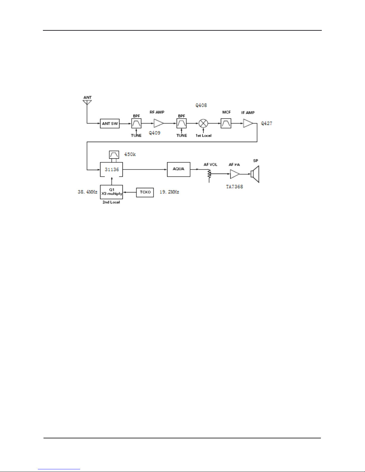
The signal received from antenna, after through the receive/transmit switch and
BFP(L413,L414) will be amplified by RF amplifier Q409(3SK318). This signal will go into the
mixer Q408 through BFP(L409,L410) and mixing with the local first oscillator signal which
comes from VCO, then generated the useful signal of the first intermediate frequency signal
38.5MHz. After filtering by crystal filter (FL403, L402), then amplifying by Q427 and going
into RF IC(IC401 LM31136)
,
it will mixing in RF IC with 2 octave of the second local oscillato r
signal which comes from temperature compensated crystal, then get the second
intermediate frequency 450K, filtering through ceramic filter FL401 and being frequency
discrimination by CR4 01, after it , signal will output from the 9th pin of RF IC(IC401
LM31136).
The above two band-pass filters BFP can be adjusted D408, D409, D406, D407(1SV305)
through variable capacitor . The variable voltage of the variable capacitor is provided by the
23
rd
pin of the CPU and commonly known as receiving EPC(Electronic power control).
The signal that output from the 9
th
pin of RF IC(IC401 LM31136) goes into the 16
th
pin of CPU, after this signal filtering by CPU, then will processing signaling (CTCSS/DCS). If
the receiving has set the signaling, the parameter of signaling that after processing by CPU
must keep the same with the preset parameter . The voice frequency signal that output from
the 25
th
pin of CPU will be amplified by Q420, then the process of signal becomes two
pathes:
①With
With
With
With
s
s
s
s
crambler
crambler
crambler
crambler
s
s
s
s
et
et
et
et
(Optional
(Optional
(Optional
(Optional
accessory)
accessory)
accessory)
accessory)
It goes into the scrambler IC701 (14th pin), after scrambler IC701 encrypted the voice
frequency signal, this signal will output from the 17
th
pin of the scrambler IC701 and
through the 8
th
pin of the line seat, it return to the CPU from the 7
th
pin of the line seat
through volume potentiometer , and drive the SPK after amplified by audio frequency power
amplifier integration IC3.

QUANZHOU WOUXUN ELECTRONICS CO.,
LTD
Model: KG- 619
Version: KG- 619- 080 6 -V1 Page 10 of 31
Circuit
Circuit
Circuit
Circuit
Description
Description
Description
Description
②
②
②
②
O
O
O
O
rdinarily
rdinarily
rdinarily
rdinarily
set
set
set
set
board(
board(
board(
board(
Without
Without
Without
Without
s
s
s
s
crambler
crambler
crambler
crambler
s
s
s
s
et
et
et
et
)
)
)
)
V
oice frequency signal will pass through the 8
th
pin of the line seat directly, and return to
the CPU from the 7
th
pin of line seat by volume potentiometer , and drive the SPK after
amplified by audio frequency power amplifier integration IC3.
(
(
(
(
4
4
4
4
)
)
)
)
Circuit
Circuit
Circuit
Circuit
description
description
description
description
about
about
about
about
the
the
the
the
voice
voice
voice
voice
prompt
prompt
prompt
prompt
This transceiver has two kinds of the voice prompt, one is signal beep prompt (BP) which
sounded from the CPU, the other is the voice prompt which provided by voice chip.
①
①
①
①
The
The
The
The
voice
voice
voice
voice
prompt
prompt
prompt
prompt
that
that
that
that
provided
provided
provided
provided
by
by
by
by
voice
voice
voice
voice
chip
chip
chip
chip
The 7
th
pin is voice frequency output port.
The 6
th
pin is voice chip oscillate port.
②Signal
Signal
Signal
Signal
beep
beep
beep
beep
prompt(BP)
prompt(BP)
prompt(BP)
prompt(BP)
which
which
which
which
sounded
sounded
sounded
sounded
from
from
from
from
the
the
the
the
CPU
CPU
CPU
CPU
The signal will pass through C445, R451, Q421 and be controlled by BP-MUTE, then the
output signal will pass through Volume/Power Switch to voice frequency amplifier and drive
loudspeaker .
(5)
(5)
(5)
(5)
VCO
VCO
VCO
VCO
s
s
s
s
chematic
chematic
chematic
chematic

QUANZHOU WOUXUN ELECTRONICS CO.,
LTD
Model: KG- 619
Version: KG- 619- 080 6 -V1 Page 11 of 31
Circuit
Circuit
Circuit
Circuit
Description
Description
Description
Description
The frequency that using by this transceiver is generated by Q306 when in transmitting
mode, and generated by Q307 when in receiving mode.
To
control the oscillating frequency via transmitting the VCO control voltage to variable
Diode (it is D302 and D303 when in transmitting mode, and it is D304 and D305 when in
receiving mode) which getted from phase comparators .
It will switch on Q308 w hen in receiving and when in transmitting, it will switch on Q305.
The output of the Q306 and Q307 will be amplified by Q302, Q303, and through
receive/transmit switch(D401/D402) to transmit to receive mixer Q408 and transmit RF
amplifier Q202.
(6)
(6)
(6)
(6)
The
The
The
The
description
description
description
description
of
of
of
of
s
s
s
s
peaker
peaker
peaker
peaker
signal
signal
signal
signal
process
process
process
process
The signal comes from the speaker will pass through IC404. When encoding the
DTMF,
CPU will turn off the speaker input signal by D414, Q424.
This signal will adjust the maximum frequency deviation through audio processor(IC404) ,
then transmit to VCO modulation input.

QUANZHOU WOUXUN ELECTRONICS CO.,
LTD
Model: KG- 619
Version: KG- 619- 080 6 -V1 Page 12 of 31
Circuit
Circuit
Circuit
Circuit
Description
Description
Description
Description
(7)
(7)
(7)
(7)
Power
Power
Power
Power
supply
supply
supply
supply
This transceiver provide s 4of the 5V power supply to each segment :
5V,
5C, 5R and
5T.
5V(IC402) will always keep output when switch on the power supply. Although 5C is power-
saving power supply output, 5R is 5 V , used for receiving and will keep output during
receiving. 5T is 5
V,
used for transmitting and will keep output during transmitting.
(8)
(8)
(8)
(8)
Adjustment
Adjustment
Adjustment
Adjustment
description
description
description
description
:
:
:
:
①CTCSS
CTCSS
CTCSS
CTCSS
The range of the CTCSS audio modulation is 0.4KHz ~0.65KHz , you can modulate
through the following component when it is beyond this range.
②DCS
DCS
DCS
DCS
The range of the DCS audio modulation is 0.4KHz ~0.65KHz , you can change it through
modulating the following component when it is beyond this range.
MOD:
To
modulate via VCO; TXCO:
To
modulate via temperature compensated crystal .

QUANZHOU WOUXUN ELECTRONICS CO.,
LTD
Model: KG- 619
Version: KG- 619- 080 6 -V1 Page 13 of 31
Circuit
Circuit
Circuit
Circuit
Description
Description
Description
Description
③The
The
The
The
maximum
maximum
maximum
maximum
modulation
modulation
modulation
modulation
of
of
of
of
the
the
the
the
speaker
speaker
speaker
speaker
The maximum modulation of the speaker: Wide bandwidth: ≤5KHz, Factory default: ≥
4.4KHz; ≤4.8KHz , generally, you only need to modulate the adjustable resistor VR401.
Narrow bandwidth : ≤2.2KHz, Factory default: ≥2.0KHz; ≤2.4KHz (If the customer have
not strict requirements.)

QUANZHOU WOUXUN ELECTRONICS CO.,
LTD
Model: KG- 619
Version: KG- 619- 080 6 -V1 Page 14 of 31
PCB
PCB
PCB
PCB
TOP
TOP
TOP
TOP
PARTS
PARTS
PARTS
PARTS
LIST
LIST
LIST
LIST
Designators
Name and Specification
Footprint
C507
Capacitance
8P
C0402
C514 C513
Capacitance
27P
C0402
C346 C345 C344 C343 C517 C569
Capacitance
100P
C0402
C527 C500 C426 C425 C424 C421
C419 C418 C415 C414
Capacitance
102P
C0402
C535 C480 C479 C478 C477 C476
C474 C472 C467 C466 C464 C461
C460 C475 R482
Capacitance
103P
C0402
C571 C562 C534 C533 C455 C454
C453 C452 C451 C450 C449 C448
C447 C446 C445 C440 C439 C438
C435 C434 C433
Capacitance
104P
C0402
C496 C524
Capacitance
220P
C0402
C536 C519 C570
Capacitance
223P
C0402
C422
Capacitance
272P
C0402
C548
Capacitance
273P
C0402
C559
Capacitance
330P
C0402
C531
Capacitance
333P
C0402
C481 C516 C505 C499 C568
Capacitance
470P
C0402
C558
Capacitance
473P
C0402
C549
Capacitance
NC
C0402
C532
Capacitance
105P
C0603
C201
Capacitance
103P
C0805
C473
Capacitance
104P
C0805
R558
Resistance
0R
R0402
R472
Resistance
100R
R0402
R569
Resistance
150R
R0402
R538 R499
Resistance
330R
R0402
R432 R413 R412
Resistance
560R
R0402
R342
Resistance
NC
R0402
R103 R102 R101 R430 R426 R425
R421 C456
Resistance
1K
R0402
R407
Resistance
1.5K
R0402
R536 R500
Resistance
2K
R0402
R503 R502 R451 R423 R408
Resistance
2.2K
R0402
R483
Resistance
2.7K
R0402
R484 R468 R424
Resistance
3.3K
R0402
C506
Resistance
3.9K
C0402

QUANZHOU WOUXUN ELECTRONICS CO.,
LTD
Model: KG- 619
Version: KG- 619- 080 6 -V1 Page 15 of 31
R523 R471 R470 R469 R406
Resistance
4.7K
R0402
R556
Resistance
5.6K
R0402
R557
Resistance
6.8K
R0402
R704 R495 R450 R449
Resistance
10K
R0402
R549 R524
Resistance
15K
R0402
R566 R478
Resistance
18K
R0402
R494
Resistance
20K
R0402
R563
Resistance
22K
R0402
R498 R575
Resistance
27K
R0402
R565
Resistance
30K
R0402
R521 R338 R574
Resistance
33K
R0402
R562 R345
Resistance
39K
R0402
R515 R514 R513 R509 R508 R507
R506 R489
Resistance
47K
R0402
R332
Resistance
51K
R0402
R570
Resistance
56K
R0402
R522 R493
Resistance
68K
R0402
R553
Resistance
82K
R0402
R552 R492 R448
Resistance
100K
R0402
R409
Resistance
120K
R0402
R525
Resistance
150K
R0402
R544
Resistance
180K
R0402
R526 R415
Resistance
220K
R0402
R561
Resistance
270K
R0402
R427
Resistance
470K
R0402
R564
Resistance
680K
R0402
R543
Resistance
1M
R0402
R405 C340
Resistance
0R
R0603
R491 R460 R459 R458 R457 R456
R455
Resistance
150K+-1%
R0603
R490
Resistance
200K+-1%
R0603
R548 R546 R545
Resistance
0.33R
R1206
R567
Exclusion Resistance
1K
RP-1206-4
R568
Exclusion Resistance
47K
RP-1206-4
VR301
Adjustable Resistance
50K
RV1208
VR401
Adjustable Resistance
100K
RV1208
C573 C518
Multi-layer Capacitance
1uF
C0805
E402 C528
Multi-layer Capacitance
4.7uF
C0805
E409 E406 C574
Multi-layer Capacitance
10uF
C0805
E408
Tantalum Capacitance
2.2uF
EIA3216
E410
Tantalum Capacitance
100uF
EIA7343
L415 L402
High frequency multi-
layer inductance
CH100NH
L0603

QUANZHOU WOUXUN ELECTRONICS CO.,
LTD
Model: KG- 619
Version: KG- 619- 080 6 -V1 Page 16 of 31
LED1
green light
G-LED
D0603
LED2
red light
R-LED
D0603
D414
Dynatron
DAN222
D-ESM
D413 D412
Diode
1SS372
D-USM
Q415 Q414 Q413 Q412 Q411 Q410
Dynatron
DTC114EE
T-ESM
Q421
Dynatron
2SK1824
T-ESM
Q425
Dynatron
2SK1588
T-SOT89
Q424 Q423
Dynatron
ISS4181
T-USM
Q418 Q419
Dynatron
5B1
T-USM
IC404
Integrate Circuit
LM4558
U-SOP8
IC3
Integrate Circuit
TA7368
U-SSOP10
IC4
Integrate Circuit
LM2904V
U-SSOP8
CR403
Crystal
32.768KHz
DS7325
IC403
chip
EM78P568-44
LQFP-44
JP401
Line Seat
JP-10
JP-10A
MIC1
Speaker
MIC
MIC-619

QUANZHOU WOUXUN ELECTRONICS CO.,
LTD
Model: KG- 619
Version: KG- 619- 080 6 -V1 Page 17 of 31
PCB
PCB
PCB
PCB
BOTTOM
BOTTOM
BOTTOM
BOTTOM
PARTS
PARTS
PARTS
PARTS
LIST
LIST
LIST
LIST
Designators
Name and Specification
Footprint
C320 C318
Capacitance
0.5P
C0402
C319
Capacitance
1P
C0402
C539 C337 C538
Capacitance
2P
C0402
C317 C308 C226 C459 C458 C457
Capacitance
3P
C0402
C544 C543
Capacitance
4P
C0402
C339 C303 C302 C301 C221 C402
C401
Capacitance
5P
C0402
C336 C335 C334 C321 C224 C545
C510
Capacitance
6P
C0402
C304 C225 C509
Capacitance
7P
C0402
C316
Capacitance
8P
C0402
C338
Capacitance
10P
C0402
C540
Capacitance
13P
C0402
C547 C546
Capacitance
15P
C0402
C542
Capacitance
18P
C0402
C512 C708 C709
Capacitance
20P
C0402
C349
Capacitance
51P
C0402
C357
Capacitance
82P
C0402
C515 C342 C541 C523
Capacitance
100P
C0402
C462 C413 C324 C323 C560 C328
C326 C325 C322 C215 C214 C213
Capacitance
102P
C0402
C565 C309 C567 C561 C469 C436
C311 C310 C305 C497 C463 C432
C110 C441 C471 C470 C468 C465
Capacitance
103P
C0402
C437 C705 C444 C702 C430 C429
C353 C307 C306 C217 C218 C431
C428 C442 R705
Capacitance
104P
C0402
C356
Capacitance
180P
C0402
C522 C521
Capacitance
220P
C0402
R520
Capacitance
223P
C0402
C537
Capacitance
224P
C0402
C554 R519
Capacitance
332P
C0402
C498 C483 C315 C314 C313 C312
C209 C205 C204 C203 C202 C495
C494 C493 C492 C490 C489 C488
C487 C208 C207 C206 C486 C485
C484 C502 C482 C503 C501 C504
Capacitance
470P
C0402
C520
Capacitance
472P
C0402
C556
Capacitance
473P
C0402

QUANZHOU WOUXUN ELECTRONICS CO.,
LTD
Model: KG- 619
Version: KG- 619- 080 6 -V1 Page 18 of 31
C553 C552
Capacitance
680P
C0402
C355 C354 C352 C348 C347 C526
C525 C351
Capacitance
NC
C0402
C107
Capacitance
0.5P
C0603
C106
Capacitance
1P
C0603
C105 C101
Capacitance
1.5P
C0603
C235 C104
Capacitance
3P
C0603
C230 C511
Capacitance
4P
C0603
C109 C103 C102
Capacitance
5P
C0603
C350
Capacitance
6P
C0603
C508 L318
Capacitance
8P
C0603
C227
Capacitance
10P
C0603
C234
Capacitance
15P
C0603
C231 C223
Capacitance
27P
C0603
C236
Capacitance
33P
C0603
C232
Capacitance
102P
C0603
C703 C443 C220 R433
Capacitance
104P
C0603
C210 C108
Capacitance
470P
C0603
C551 C550
Capacitance
683P
C0603
C228 C229 C233 C222
Capacitance
NC
C0603
R105 R104 SCR101 R701 SCR102
R401 R314 R303 R302 R301 R573
R404 R403 R402 R529 C557
Resistance
0R
R0402
R319 R318 R219
Resistance
10R
R0402
R211
Resistance
22R
R0402
R435 R330 R208 R207 R206 R437
R436 R440 R439 R438
Resistance
47R
R0402
R323 R326 R474 R327 R325 R324
R322 R475 R476
Resistance
100R
R0402
R337
Resistance
180R
R0402
R537
Resistance
330R
R0402
R410 R306 R305 R210 R411
Resistance
560R
R0402
R218 R205
Resistance
680R
R0402
R479 R336 R334 R321 R480 R572
R467
Resistance
NC
R0402
R703 R417 R416 R311 R310 R309
R308 R422 R429 R501 R431 C706
Resistance
1K
R0402
R307
Resistance
1.2K
R0402
R530
Resistance
1.8K
R0402
R486 R473
Resistance
2K
R0402
R702 R312 R209
Resistance
2.2K
R0402
R335 R485 R488
Resistance
3.3K
R0402
R487 R528
Resistance
3.9K
R0402

QUANZHOU WOUXUN ELECTRONICS CO.,
LTD
Model: KG- 619
Version: KG- 619- 080 6 -V1 Page 19 of 31
R571 R465 R464 R463 R420 R418
R414 R317 R203 R202 R201 R527
R462 R461 R419 R516 R466
Resistance
4.7K
R0402
R554 R532 R555
Resistance
5.6K
R0402
R316 R315 R204 R453 R452 C555
Resistance
10K
R0402
R340 R531
Resistance
15K
R0402
R341
Resistance
20K
R0402
R550
Resistance
27K
R0402
R434 R518 R517
Resistance
33K
R0402
R339
Resistance
39K
R0402
R511 R215 R214 R213 R510 R150
Resistance
47K
R0402
R331
Resistance
51K
R0402
R551
Resistance
91K
R0402
R445 R447 R446 R328 R313 R442
R441
Resistance
100K
R0402
R505 R504 R444
Resistance
120K
R0402
R333 R329 R320 R212 R443
Resistance
150K
R0402
R535 R534 R533
Resistance
180K
R0402
R344 R454
Resistance
200K
R0402
R477
Resistance
220K
R0402
R481
Resistance
390K
R0402
R542 R541 R540 R539
Resistance
1M
R0402
R560 R559
Resistance
1M8
R0402
C704
Resistance
0R
C0603
R220
Resistance
10R
R0603
R217 R216
Resistance
270R
R0603
R221 R222
Resistance
0R
R0805
C219
Multi-layer Capacitance
1uF
C0805
E401 E302
Multi-layer Capacitance
4.7uF
C0805
C427 E411 C564 C563 C111
Multi-layer Capacitance
10uF
C0805
C707
Multi-layer Capacitance
NC
C0805
E304
Tantalum Capacitance
0.1uF
EIA3216
E305
Tantalum Capacitance
0.22uF
EIA3216
E407 E303
Tantalum Capacitance
2.2uF/10V
EIA3216
E306
Tantalum Capacitance
4.7uF/16V
EIA3216
E301 E403 E405 E404
Tantalum Capacitance
10uF/16V
EIA3216
L403
High frequency multi-
layer inductance
CH12NH
L0402
Table of contents
Other QUANZHOU WOUXUN Transceiver manuals
Popular Transceiver manuals by other brands

ELECRAFT
ELECRAFT K3EXREF Installation and operation

BesTrans
BesTrans BTW-Mini2 manual

Microhard Systems
Microhard Systems n920BT operating manual

Em-Trak
Em-Trak A100 product manual

Technisonic Industries Limited
Technisonic Industries Limited TFM-530 Installation and operating instructions

PRESIDENT
PRESIDENT Barry FM owner's manual