QUANZHOU WOUXUN ELECTRONICS CO., LTD Model: KG-689
Version: KG-689-0801-V1 Page 6 of 35
APO
BEEP/CTCSS
ARX
AN SQL
RXI
14
9
U261
T463
U460
T451
SB
T453
AFC
SP MUTE
15
20
72
71
T455
SP
Chart 3
U8 11
MCU
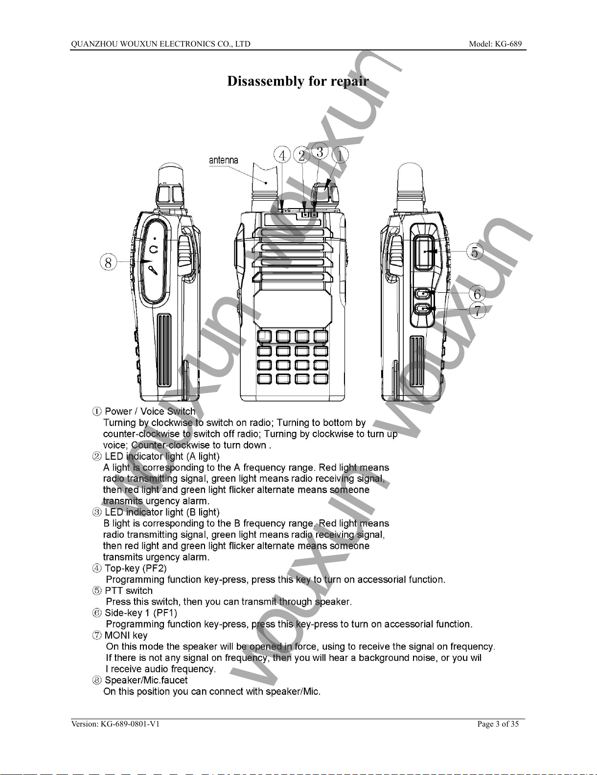
Circuit Description
(3). Intermediate amplifier
As Chart 3 shows, the first intermediate frequency blow up by T253, then enter U261 (FM signal frequency
modulation integrate circuit). At time signal will mix with second root flap, switch to second IF signal.
Through 450K filter, except that all disturb signals will be unchained, then be blew up and inspected.
Audio frequency amplifier
The audio frequency signal comes from inspected filter and be aggravated, then input to MCU(U811), then
through adjust potentiometer, blow up by U460, get the audio frequency power, contact with MIC via T463.
Squelch circuit and signal intensity list
Check by U261: Output yawp signal, then put it into CPU (U811) and deal with it by the 25 feet interior.
According to the electricity level signal which MCU get, one side, it can control SP MUTE, APX and AFC, to
complete to control audio frequency output circuit (The level of CPU inside control system is from 1 to 9
grades, it can program by software or by keyboard). On the other side, it can control the signal strong list of
LCD screen.
3. Transmit system
(1). Speaker amplifier
As show in Chart 4, audio frequency signal comes from MIC will be aggravated, then limited blow up by
U411-A, all distortion audio frequency signals will be unchained by adjacent filter which makes up with
U411-B caused by limited blow up.
Modulate circuit
The signal comes from speaker amplifier modulated by adjust potentiometer VR382, then modulating
changeable reactance by varactors tube D348.