manuals.online logo
Brands
  1. Home
  2. •
  3. Brands
  4. •
  5. Qube
  6. •
  7. Automobile Accessories
  8. •
  9. Qube AP1 Owner's manual

Qube AP1 Owner's manual

©Qube Engineering 2009 Qube’s AP1 LED Dash DIY Kit Supplemental Instructions Page 1
v 1. 0
Qube Engineering
21914 Palos Verdes Blvd
Torrance, CA 90503
818-271-QUBE (7823)
art@qube-engineering.com
©Qube Engineering 2009
©Qube Engineering 2009 Qube’s AP1 LED Dash DIY Kit Supplemental Instructions Page 2
Qube’s AP1 LED Dash Do-It-Yourself Kit
Supplemental Instructions are intended for
use solely with Qube’s AP1 LED Dash
Installation Instructions. Please use this
supplement as a direct replacement for
steps 18-25 of Qube’s AP1 LED Dash
Installation Instructions available from
www.qube-engineering.com.
Additionally, you will not need to return
any core parts to Qube Engineering.
©Qube Engineering 2009 Qube’s AP1 LED Dash DIY Kit Supplemental Instructions Page 3
Power Connection Cable
LED Array Board
Cable Ties
If your package does not contain all of the following parts, please contact
Qube Engineering before continuing.
Owner’s Manual
Fuse Box Power Splitter
Screw Cap Removal Tool
Color Diffuser Board
Attachment Screws
White Tape Strips
Waxed Paper
©Qube Engineering 2009 Qube’s AP1 LED Dash DIY Kit Supplemental Instructions Page 4
Clean Microfiber
Cloth
Small snips suitable for plastic
Thin Flathead Screwdriver
Philips ScrewdriverScissors
Rotary Tool (Dremel) with plastic cutting, grinding,
Abrasive, and Cut Off bits
Compressed Air
Pencil with eraser on the end
Glass Cleaner Plastic Cleaner
Soldering Iron, Soldering Flux, and Wire Solder
©Qube Engineering 2009 Qube’s AP1 LED Dash DIY Kit Supplemental Instructions Page 5
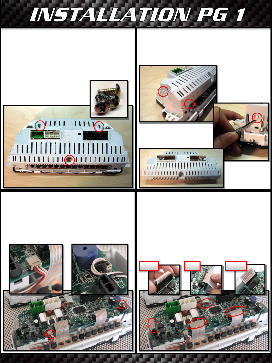
1) Set your gauge cluster face down on a
clean flat surface. Do not put unnecessary
force on the gauge cluster as it is resting on
the plastic tabs at the base of the cluster.
Using the Philips screwdriver, remove the 3
screws that hold the back cover on. Set
them aside.
2) Using the small flathead screwdriver,
undo the 4 tabs that hold the white back
cover onto the gauge cluster assembly.
Remove the back cover and set it aside.
3) With the cluster computer exposed,
unplug the two 3-pin harnesses. You should
be able to do this by gently wiggling the
harness out. Use a small flathead
screwdriver to help release the harness if
necessary.
4) Unplug the four ribbon cables from the
cluster computer. The ribbon cables are
held in place with plastic clips. Pinch and
pull upwards on the sides of the plastic clips
to “unlock” them, bend the ribbons
backwards to straighten the part where the
hooks engage them, unhook the ribbon
cables, then unplug them.
Unlock Bend Unhook
©Qube Engineering 2009 Qube’s AP1 LED Dash DIY Kit Supplemental Instructions Page 6
5) While holding the ribbon cables out of the
way, lift cluster computer off of the gauge
cluster housing. Set it aside.
6) Twist each exposed bulb on the upper
portion of the gauge cluster housing 1/8th of
a turn counterclockwise to remove them.
You should remove the following bulbs….
-2 brown base bulbs with blue bulb covers
-2 red base bulbs
-3 light grey base bulbs
-3 dark grey base bulbs
Set the bulbs aside.
7) Carefully remove the upper trace
filament from the gauge cluster housing.
You may want to use the small flat
screwdriver to help certain parts of the
filament off the housing. Set it aside.
8) Twist the remaining bulbs on the lower
row of the gauge cluster housing 1/8th of a
turn counterclockwise to remove them. You
should remove the following bulbs…
-9 dark grey base bulbs
-1 black base bulb
Set the bulbs aside.
©Qube Engineering 2009 Qube’s AP1 LED Dash DIY Kit Supplemental Instructions Page 7
9) Carefully remove the lower trace filament
from the gauge cluster housing. You may
want to use the small flat screwdriver to
help certain parts of the filament off the
housing. Set it aside.
10) Turn the gauge cluster face up. Remove
and set aside the rubber pads from the tabs
at the base of the gauge cluster.
11) Undo the clips that hold the black
plastic frame onto the gauge cluster. There
is one clip on each side and four clips along
the bottom. Set the black plastic frame
aside.
12) Lift off the clear plastic cover of the
gauge face. If it sticks to the black glass
piece, carefully pull them apart. Set the
clear piece aside.
©Qube Engineering 2009 Qube’s AP1 LED Dash DIY Kit Supplemental Instructions Page 8
13) Lift off the black glass portion of the
gauge face. While feeding the ribbon cable
through the gauge cluster housing, remove
the black glass and set it aside. Two square
rubber plugs will pop out with the glass
piece. Set them aside.
14) Place the clear plastic cover of the gauge
face on top of the black glass portion to
protect the surfaces of both. Set them
aside.
15) Remove the long rubber seal and two
remaining square rubber plugs from the
plastic housing. Set them aside with the
other two square rubber plugs.
16) Remove the yellow and orange color
filter plate. Set it aside.
©Qube Engineering 2009 Qube’s AP1 LED Dash DIY Kit Supplemental Instructions Page 9
17) Remove the two pushbutton boards
from the plastic housing. Do this by pushing
on the backside of the board with the small
screwdriver through the access holes in back
while pushing downward on the two tabs on
the bottom side of the board. Set the
boards aside.
18) Remove the four black template pieces
from the housing. Do this by gently pushing
on them from the backside through the bulb
access holes with the eraser side of the
pencil. As each piece is removed, put it
adhesive side down on the wax paper. Set
them aside.
19) Using small modeling snips or a small rotary tool cutoff wheel, remove the small
vertical plastic pieces from the plastic housing. Shown in red. Be careful to leave the
pieces not highlighted in red.
©Qube Engineering 2009 Qube’s AP1 LED Dash DIY Kit Supplemental Instructions Page 10
20) Using the rotary tool plastic cutting bit, roughly remove the areas shown in red. Be
careful not to cut into the sides of the light tunnel areas. Caution on the side of cutting less
material, as you will still make a final pass with the grinding bit.
LIGHT TUNNELS
©Qube Engineering 2009 Qube’s AP1 LED Dash DIY Kit Supplemental Instructions Page 11
21) Use the grinding bit to finish cutting and smoothing out the material. The housing does
not need to be perfectly smooth. The goal is to allow enough room for the LED Array board
to fit snugly all the way down to the bottom of the modified housing. Do a test fit of the LED
Array board in the housing. Remove more material if necessary. Once the board fits
correctly, remove the LED array board and set it aside.
22) Use a deburring tool, X-acto knife, or your fingers to remove any burrs left on the plastic.
Use the compressed air to blow all remaining dust off of the housing. Make sure to remove
any dust from inside the light tunnels as well. The end result should look like this….
©Qube Engineering 2009 Qube’s AP1 LED Dash DIY Kit Supplemental Instructions Page 12
25) Fold the tape strip over the top side of
the light tunnel. Press all contact surfaces
into place using the eraser end of the pencil.
Repeat to cover the slits in the 5 remaining
light tunnels. An extra tape strip is included.
23) Wash your hands and clean off your
clothes and work surface. You want to avoid
getting dirt and dust on the gauge cluster
pieces once you are done with the plastic
modification.
24) Fold the white tape strips in half to
lightly mark the center of the tape strips.
Remove one of the tape strips and from the
backside of the housing, put it half way
down into one of the six light tunnels
shown.
26) Put the LED Array Board in the Gauge
Cluster Housing. Use the two self-threading
attachment screws to attach the board to
the housing. Attach the screws from the
backside as shown. DO NOT OVERTIGHTEN!
©Qube Engineering 2009 Qube’s AP1 LED Dash DIY Kit Supplemental Instructions Page 13
27) Take the upper trace filament and turn
it over so the side with the two hard wires
on it faces upwards. Using the small snips,
cut off the two hard metal wires as close to
the trace filament as possible. Four cuts
total will remove the two wires.
28) using the scissors, cut the upper trace
filament along the line shown below. You
will not use the smaller piece.
29) Using the rotary tool small grinding bit,
remove the protective clear coat from a
1/8th inch strip of the wire trace shown here.
Only a very light sanding is necessary to
expose the wire trace. The wire trace will
appear shiny afterwards.
30) Apply solder flux to the exposed part of
the wire trace.
©Qube Engineering 2009 Qube’s AP1 LED Dash DIY Kit Supplemental Instructions Page 14
31) Heat the soldering iron. Melt a small
drop of solder on the tip of the hot soldering
iron. Touch the hot drop of solder to the
exposed wire trace just until the solder sticks
to the exposed trace. You should not need
to touch the filament with the soldering iron
directly, just with the hot drop of solder. It
should only take a split second. DO NOT
OVERHEAT THE TRACE FILAMENT.
32) Install the modified upper trace filament
back onto the plastic gauge cluster housing.
33) Apply soldering flux and a hot drop of
solder to the exposed end of the yellow wire
coming from the LED Array board. Solder
the yellow wire onto the solder drop you
placed on the trace filament. AGAIN, DO
NOT OVERHEAT THE FILAMENT. Turn off the
soldering iron when done with this step.
34) Install three dark grey based bulbs and
two brown based bulbs as shown. You will
not use the three light grey or two red based
bulbs.
BROWN
DARK GREY
©Qube Engineering 2009 Qube’s AP1 LED Dash DIY Kit Supplemental Instructions Page 15
35) Cut the lower trace filament along the
line shown. You will not use the small piece.
36) Install the modified lower trace filament
onto the plastic gauge cluster housing.
37) Install the 9 dark grey based bulbs and
one black based bulb as shown.
38) Turn the gauge cluster assembly back
over. Reinstall the four black template
pieces onto the gauge cluster assembly.
BLACK
DARK GREY
EMPTY
©Qube Engineering 2009 Qube’s AP1 LED Dash DIY Kit Supplemental Instructions Page 16
39) Install the two pushbutton boards into
the gauge cluster assembly. The one with
the black wire goes on the left and the one
with the red wire goes on the right. Make
sure to fish the wire harnesses through the
hole in the cluster assembly so they come
out the backside.
40) Reinstall the long rubber seal and two of
the square rubber plugs on the right side of
the gauge cluster. The remaining two rubber
plugs will be used at a later step.
41) Use the plastic cleaner and microfiber
towel to clean any smudges, dirt, or
fingerprints from the front and back of the
color diffuser board. Install it in the gauge
cluster housing, color filter side up.
42) Use the compressed air to blow any dust
particles off of the gauge cluster assembly
including the color diffuser board.
©Qube Engineering 2009 Qube’s AP1 LED Dash DIY Kit Supplemental Instructions Page 17
43) Use the glass cleaner and microfiber
cloth to clean both sides of the black glass
piece. Fish the wire ribbon and electrical
board through the opening in the gauge
cluster housing. Use the compressed air to
blow away any dust, then lay the black glass
piece over the color diffuser board.
44) Install the remaining two square rubber
plugs on the top side of the black glass
piece. The black glass piece should be held
snugly in place between the square rubber
pieces on the top and right side and plastic
standoffs on the left and bottom side.
45) Using the plastic cleaner and microfiber
cloth, clean the front and backside of the
clear plastic cover piece. Install it over the
black glass piece. It is positioned using the
two plastic pins at the top of the gauge
cluster housing. Use the compressed air to
remove any dust between the two pieces.
46) Install the black plastic trim piece over
the clear plastic cover piece. Snap it into
place. Attach the two rubber pads over the
tabs at the base of the gauge cluster.
©Qube Engineering 2009 Qube’s AP1 LED Dash DIY Kit Supplemental Instructions Page 18
47) Turn the gauge cluster assembly back
over. Plug the wire harness with the black
wire in to the female wire harness on the
right side of the LED array board.
48) Move the ribbon cables and power
harness out of the way and reinstall the
gauge cluster computer back onto the gauge
cluster. Make sure the yellow wire doesn’t
get pinched between the housing and the
computer board. Reattach the wire harness
with the red wire to the female wire harness
on the gauge cluster computer.
49) Reattach the four ribbon cables. Push
downward on the pinchable part of the
plastic harness to lock the ribbon cables in
place.
50) Reinstall the back cover onto the gauge
cluster assembly. The power harness should
emerge from the bottom side of the
assembly from between the gauge cluster
assembly and back cover.
©Qube Engineering 2009 Qube’s AP1 LED Dash DIY Kit Supplemental Instructions Page 19
51) Use the philips screwdriver to reattach two of the three screws that fasten the back
cover in place. The Screw from the middle of the lower portion of the gauge cluster is no
longer used.
DO-IT-YOURSELF SUPPLEMENTAL INSTALLATION
COMPLETE!
Please continue on to step 26 in the AP1 LED Dash Installation Instructions. Enjoy your
new LED Dash!

Popular Automobile Accessories manuals by other brands

ECS Electronics MB-080-B1 Fitting instructions

ECS Electronics

ECS Electronics MB-080-B1 Fitting instructions

Thule 39 manual

Thule

Thule 39 manual

JMD Handy-Baby user manual

JMD

JMD Handy-Baby user manual

DoubleTake SeatBack Plates installation instructions

DoubleTake

DoubleTake SeatBack Plates installation instructions

BEIJING TIANYUAN-TECH MOTO-1 user manual

BEIJING TIANYUAN-TECH

BEIJING TIANYUAN-TECH MOTO-1 user manual

Toro 07337 Parts List & Assembly Instructions

Toro

Toro 07337 Parts List & Assembly Instructions

ECS MT-131-BHU manual

ECS

ECS MT-131-BHU manual

Westfalia F-2010-2B instruction manual

Westfalia

Westfalia F-2010-2B instruction manual

Thule HULL-A-PORT 835xt manual

Thule

Thule HULL-A-PORT 835xt manual

SportRack A30404TW200 manual

SportRack

SportRack A30404TW200 manual

Sunit fd user guide

Sunit

Sunit fd user guide

Circontrol CCL-PT3 SMART installation manual

Circontrol

Circontrol CCL-PT3 SMART installation manual

MVG 3111 A installation instructions

MVG

MVG 3111 A installation instructions

Xpresskit RFLMIT3 quick start guide

Xpresskit

Xpresskit RFLMIT3 quick start guide

Seat 5FJ.071.691 installation instructions

Seat

Seat 5FJ.071.691 installation instructions

Dakota Digital BIM-16-1 manual

Dakota Digital

Dakota Digital BIM-16-1 manual

NavLinkz RL4-LR17 manual

NavLinkz

NavLinkz RL4-LR17 manual

UGREEN Car Cup Holder Phone Mount manual

UGREEN

UGREEN Car Cup Holder Phone Mount manual

manuals.online logo
manuals.online logoBrands
  • About & Mission
  • Contact us
  • Privacy Policy
  • Terms and Conditions

Copyright 2025 Manuals.Online. All Rights Reserved.