Queenax PF325 User manual
Installation Assembly Guide
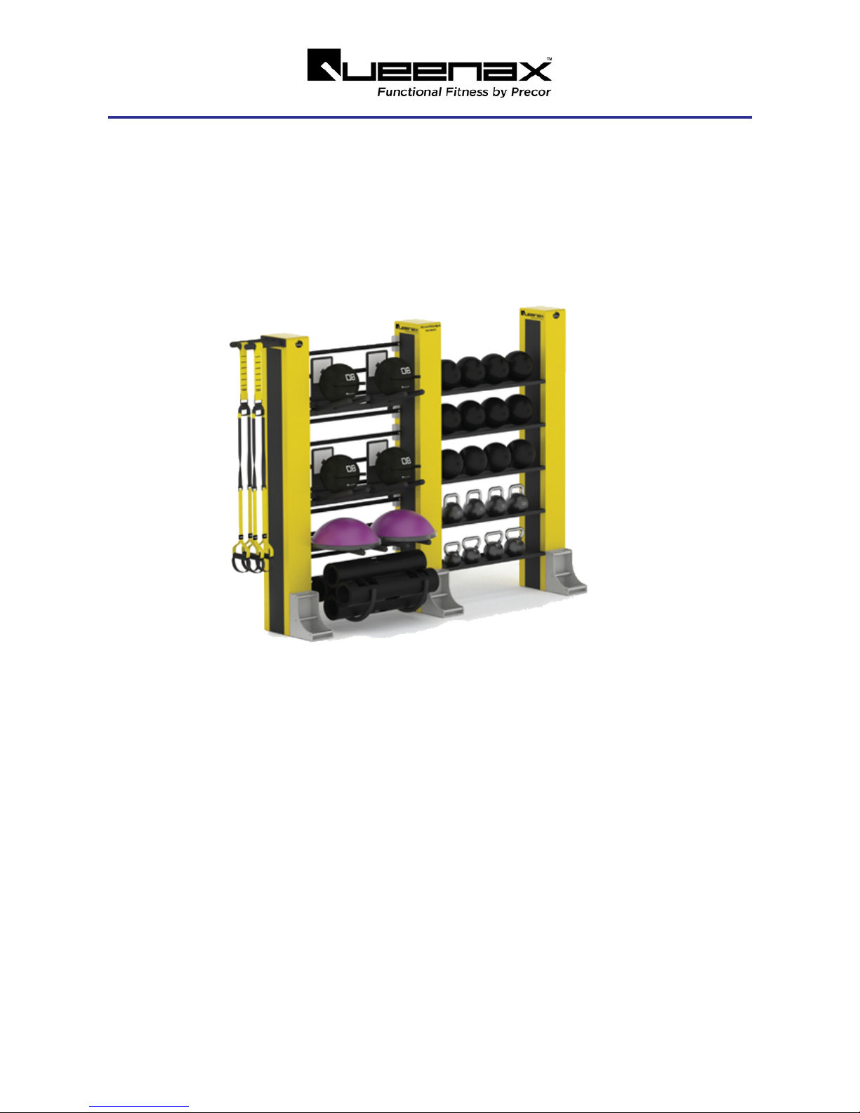
QUEENAX™ PF325 2D
WALL SOLUTION

Contents
1Introduction 1
Additional Documentation 1
Contact Information 1
2General Information 3
Tools 3
Safety Equipment 4
Orientation Convention 4
Equipment Part and Option Identification 4
Torque Specifications 5
Cleaning 5
3Getting Started 7
Baseline installation procedure 7
Installation and assembly requirements 7
Receiving Parts 7
Assembly and Installation Tips 8
Unpacking boxes 8
Fastener Tips 8
4Assembly and Installation 9
Introduction 9
Procedure 9
Prepare Towers for installation 9
Anchor the towers to the floor 12
Install the Tower Placards 15
Install the Wall Bars 15
Install the Easy Shelf 35s 17
Anchor the Floor Fixings to the floor 19
Install remaining panels 22
Install the Unit Optionals 22
Install Placards, Labels, and Decals 23
ii

Horizontal VIPR & Roller Shelf Optional Assembly 24
25
Bulgarian Bag and Ball Optional Assembly 25
25
Horizontal Bag Shelf Optional Assembly 26
4Floor Anchoring Requirements 28
Floor material requirements 28
Anchor bolt requirements 28
Torque specification 28
Approved anchor bolt types 28
Anchor bolt installation Summary 28
Appendix A : Edition Information i
Edition i
Copyright i
Trademarks i
Safety Instruction i
Safety Notices i
iii

1Introduction
This document contains information required to install and assembly the Queenax PF325 2D Wall
Solution storage unit. Follow the assembly instructions in the order given to correctly and efficiently
assemble and install the unit.
If you are not a Precor Queenax certified servicer, you must not attempt to install and assemble this
Precor product. Call your dealer for information.
WARNING:Only Precor Queenax certified service providers and technicians are author-
ized to assemble and install this product. Many parts are large and heavy requiring multiple
technicians and specialized lift equipment to assembly. Personal injury or equipment dam-
age can occur during installation and during use if improperly assembled and installed.
Additional Documentation
You can also view the install assembly guide online at : Online Service Manual
Contact Information
Contact Precor Queenax installation coordinator or e-mail at
queenaxinstalls@precor.com
with any
issues prior to or during installation.
See Also
"General Information" on page3
1
1 Introduction

"Getting Started" on page7
"Assembly and Installation" on page9
"Floor Anchoring Requirements" on page28
2
1 Introduction

2General Information
This section provides general information that will help you to use this guide to assemble and install
the PF325 2D Wall Solution storage unit including the required tools, specifications, parts iden-
tification, unit orientation, cleaning, etc.
Tools
The following tools are required to assemble Queenax products:
Note:One set of power tools per installer is recommended.
The following tools are required to assemble Queenax products:
l½” Drive hammer drill or Concrete drill
omasonry bits appropriately sized for anchor types (refer to mfg's guidelines for selecting
anchor bolt bit sizes.)
o3 mm, 6 mm, 10.5 mm, and 12.5 mm metal cutting bits
l½” Drive Battery Impact Driver
lBattery Angle Grinder
oCutting disc and abrasive disc (grit #40)
lOscillating Tool (for cutting flooring)
oWood and scraper blades
lMetric tape measure
lLaser measure
lUtility Knife
lTap driver (10 mm & 12 mm cutting threads
lRubber mallet
lHammer
lLadders
lMetric combination wrenches (13 mm, 17 mm, comm, and 22 mm)
l½” and 3/8” drive ratchets
lTorque wrench 100 ft-lbs (136 N•m
lMetric hex key set
l½” metric hex key sockets from (6 mm – 10 mm, 13 mm, 17 mm, comm, and 22 mm)
o1 short set and 1 long set with ball end
l3/8” metric hex sockets (13 mm, 17 mm, and comm
l½” universal joint
3
2 General Information
Tools

l½” to 3/8” socket adapter
l½” short and long extensions
lVacuum cleaner
Note:One set of power tools per installer is recommended.
Safety Equipment
The following safety equipment is recommended:
lSafety vest
lGloves
lRespirator
lHard hat
lEarplugs
lSafety glasses
lSafety toe work boots
Orientation Convention
The equipment front, right, left, and back orientation.
Equipment Part and Option Identification
IMPORTANT: Always purchase OEM replacement parts and hardware from Precor. If you
use parts not approved by Precor, you could void the Precor Limited Warranty. Use of parts
not approved by Precor may cause injury.
4
2 General Information
Safety Equipment

Torque Specifications
This table provides a summary of system component specifications.
System Component Specification
M10 Bolt torque 34 ft-lbs (46 Nm)
M12 bolt torque 58 ft-lbs (79 Nm)
M14 bolt torque 94 ft-lbs (127 Nm)
Expansion anchor bolt torque137 ft-lbs, (50 Nm)
Note: 1) see "Floor Anchoring Requirements" on page28
Cleaning
1. Wipe down equipment with recommended cleaning solution.
lGeneral: 1 oz. mild soap to 30 oz. water. .
5
2 General Information
Torque Specifications

CAUTION: Do not use acidic cleaners and do not spray directly onto the equipment surfaces.
2. Rinse using a clean lint-free cloth and dampened with water only. Dry completely with another
clean lint-free cloth.
See Also
"Introduction" on page1
"Getting Started" on page7
"Assembly and Installation" on page9
"Floor Anchoring Requirements" on page28
6
2 General Information
Cleaning

3Getting Started
Read and review the following information before starting the assembly and installation of the unit.
There are several tasks in the "Installation and assembly requirements" section (see "Installation and
assembly requirements" below) that must be completed before you can start the installation.
There is also additional information to help you prepare and perform a safe and efficient installation.
Baseline installation procedure
This assembly installation procedure provides a baseline procedure that will reliably install the unit.
With experience you may find more efficient methods of installation. Always verify changes and/or
alternate methods of assembly and installing the unit with the Precor Queenax installation coordinator.
IMPORTANT: Always verify any procedural changes or alternative methods to this installation
procedure with the Precor Queenax installation coordinator.
Installation and assembly requirements
You must have the following items and conditions before you can start the equipment installation.
lSite Survey: You must have an approved site survey before you can install the unit.
WARNING:Review the site survey prior to ANY drilling and make sure that there are no
conditions or obstacles (such as electrical conduit, post-tension rebar, etc.) that could cause
personal or facility damage while drilling.
lRendering: You must have a copy of the unit build rendering before starting installation.
lBeams and fasteners: You must have the correct number of beams. Use the rendering to
verify that the correct number of beams have been received. If the unit includes overhead
beams, make sure the correct number of beam joining fastener packages were received.
lRoom Size: Verify that the room is large enough to install and use the unit.
oMake sure the room height, including any hanging obstructions such as sprinklers and
light fixtures, will not interfere with the height requirements.
oMake sure that there is enough space around the unit to allow installation and use of the
optionals and training apps without interference.
Receiving Parts
lUse the rendering and parts invoices (packing list) to verify that all listed part boxes were
received.
7
3 Getting Started
Baseline installation procedure

Assembly and Installation Tips
Unpacking boxes
lPlace part and assembly boxes as close to the installation location as possible.
lKeep all individual part and assembly fastener hardware together. Do not intermix or use
fastener hardware for other than the intended part installation.
Fastener Tips
lKeep fastener hardware with the intended part or assembly: Each training app and optional
shipping box contains all the parts and fasteners required to assembly and install that item.
Keep all fasteners shipped with a part together. Do not interchange, mix, or use fasteners from
one part to install a different part. Doing so will make it difficult to complete the build and if a
fastener is missing, make it difficult to know which fastener type is missing and needs replace-
ment.
IMPORTANT: Do not interchange optional and training app part fasteners. When unpacking
part boxes, keep the fasteners with the part and do not intermix with other parts. This will
make it easy to assemble and identify any missing fasteners.
:
See Also
"Introduction" on page1
"Assembly and Installation" on page9
"Floor Anchoring Requirements" on page28
8
3 Getting Started
Assembly and Installation Tips

4Assembly and Installation
Introduction
This assembly installation procedure provides a baseline procedure that will reliable install the unit.
With experience you may find more efficient methods of installation. Always verify changes and/or
alternate methods of assembly and installing the unit with the Precor Queenax product installation
department.
IMPORTANT: Always verify any procedural changes or alternative methods to this installation
procedure with the Precor Queenax installation department.
Before starting make sure you have reviewed and completed all tasks listed in the Getting Started sec-
tion, see "Getting Started" on page7.
IMPORTANT: Review the Getting Started section (see "Getting Started" on page7) and
adhere to safety information before starting the assembly and installation process.
Procedure
Prepare Towers for installation
1. Unpack and lay the three beam section 250 assemblies on the floor as close as possible to the
install location. Refer to the rendering for specific part location and attachment information.
2. Attach the strap rack to the tower terminal 35 cm side using a 6 mm hex key to secure the M10
hex key bolt, M10 flat washer, and M10 nut. Fully tighten fasteners and torque to 34 ft-lbs (46
Nm).
9
4 Assembly and Installation
Introduction

ID Qty PN Description
1 1 Q2017PFY-101 TOWER TERMINAL 10,PF YELLOW
2 1 Q40728-101 STRAP RACK
3 4 CWKFCN010-008 NUT,LOCK,FULL,M10,NYLON INSERT,STL,CZ
4 4 CWWNCN010-025 WASHER,FLAT,STEEL,METRIC,M10 X 40 OD X 2.5T,
CZ
5 4 CWCNCN010-030 SCREW,FHC,M10X1.5X30,STL,CZ
Note: Part qty on a per unit basis.
3. Attach the assembled strap rack tower terminal to the left beam section 250 tower using a 19
mm wrench secure the M12 bolt, M12 flat washer, M12 lock washer, and M12 nut. Fully tighten
all fasteners and torque to 58 ft-lbs (79 Nm)
ID Qty PN Description
1 1 Q2017PFY-101 TOWER TERMINAL 10,PF YELLOW
2 4 CWHMCN012-030 SCREW,HHC,M12X1.75X30,STL,CZ
3 4 CWWNCN012-025 WASHER,FLAT,STEEL,METRIC,M12 X 36 OD X
2.5T, CZ
4 4 CWWNCN012-025 WASHER,FLAT,STEEL,METRIC,M12 X 36 OD X
2.5T, CZ
10
4 Assembly and Installation
Procedure

ID Qty PN Description
5 8 CWWBWCN012-023 WASHER, SPLIT, M12 X 2.3MM THICK, CZ
6 8 CWKARCN012-010 NUT,PLAIN,HEX,M12,STL,CZ, DIN 934
7 1 Q2275PFY-101 ASSY,BEAM,SECTION,250 S 2.0,PF YELLOW
8 1 Q40728-101 STRAP RACK
Note: Part qty on a per unit basis.
4. Attach the remaining two tower terminals on the center and right beam section 250 towers.
Using a 19 mm wrench fully tighten all fasteners and torque to 58 ft-lbs (79 Nm)
ID Qty PN Description
1 1 Q2017PFY-101 TOWER TERMINAL 10,PF YELLOW
2 4 CWHMCN012-030 SCREW,HHC,M12X1.75X30,STL,CZ
3 4 CWWNCN012-025 WASHER,FLAT,STEEL,METRIC,M12 X 36 OD X 2.5T,
CZ
4 4 CWWNCN012-025 WASHER,FLAT,STEEL,METRIC,M12 X 36 OD X 2.5T,
CZ
5 8 CWWBWCN012-023 WASHER, SPLIT, M12 X 2.3MM THICK, CZ
6 8 CWKARCN012-010 NUT,PLAIN,HEX,M12,STL,CZ, DIN 934
11
4 Assembly and Installation
Procedure

ID Qty PN Description
7 1 Q2275PFY-101 ASSY,BEAM,SECTION,250 S 2.0,PF YELLOW
Note: Part qty on a per unit basis.
5. Attach the floor fixing 25 to the 25 cm side of the tower for all three towers. Secure using a 6 mm
hex key and 17 mm wrench to tighten the M10 hex key bolt, M10 flat washer, M10 lock washer,
and M10 nut. Fully tighten all fasteners and torque to 34 ft-lbs (46 Nm). Note that the strap rack
is attached on the left side of the tower, see rendering for specific attachment location.
ID Qty PN Description
1 1 Q2275PFY-101 TOWER - YELLOW
2 4 Q2052QMS-101 FLOOR FIXING 25, SILVER
3 4 CWKFCN010-008 NUT,LOCK,FULL,M10,NYLON INSERT,STL,CZ
4 4 CWWNCN010-025 WASHER,FLAT,STEEL,METRIC,M10 X 40 OD X 2.5T,
CZ
5 4 CWWKCN010-019 WASHER, FLAT, STEEL, METRIC, M10 X 1.9MM
THICK, CZ
6 4 CWTECN010-030 SCREW,BHC,M10X1.5X30,CZ
Note: Part qty on a per unit basis.
Anchor the towers to the floor
6. Use the rendering to layout and mark the location for the left, center, and right tower floor fixing
assemblies. Make sure that the unit layout provides sufficient unobstructed area around the top
and sides of the equipment for installation and use.
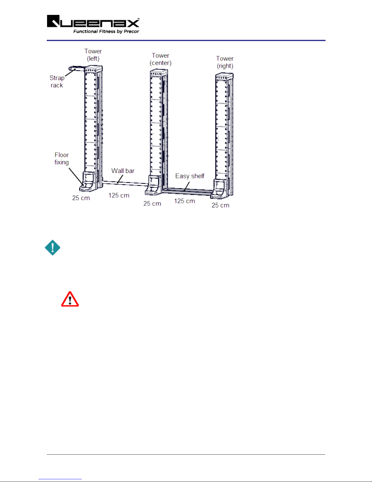
7. Precisely stand and position the three tower floor fixing assemblies per the rendering spe-
cification. Set the towers 125 cm apart. You can use a wall bar 125 and easy shelf 35 to set the
exact spacing between the left, center, and right towers respectively. Make sure the three
towers are positioned equal distance from the wall and square relative to each other.
12
4 Assembly and Installation
Procedure
8. Verify that the customer approves the unit location. Always receive customer approval before
doing any floor covering alterations or drilling of the anchor fastener holes.
IMPORTANT: Do not make any alterations to the flooring or drill any anchor bolt holes before
verifying location with the customer.
9. Floor covering installationsonly:Remove the floor covering from underneath each tower. Pre-
cisely trace the outline of the tower with the floor fixing attached. Then carefully cut and remove
the flooring. Replace the tower back into the final position. Repeat for each tower.
WARNING:The equipment towers and floor fixings must be installed directly on the
concert surface. Any floor coverings must be removed from underneath the towers
and floor fixings. Floor coverings can cause premature loosening of fasteners caus-
ing possible hardware failure and harm to exercisers.
10. Mark the four anchor bolt positions located on inside of the tower footplate, refer to the
Tower
Anchor Bolt Pattern
diagram below for anchor bolt location information. Do not mark the floor fix-
ing anchor locations at this step.
13
4 Assembly and Installation
Procedure

IMPORTANT: Before anchor bolt installation read the Floor Anchoring Requirements topic
(see "Floor Anchoring Requirements" on page28). Only use the Precor approved anchor bolt
types (see "Approved anchor bolt types" on page28) and adhere to the anchor bolt install-
ation depth and position instructions (see "Anchor bolt installation Summary" on page28).
11. Move the towers from the install location. Then use the marked tower anchor bolt locations to
drill and install the anchor bolts for the left, center, and right towers. The size of the anchor hole
and depth will depend on the type of anchor used, refer to "Approved anchor bolt types" on
page28 and "Anchor bolt installation Summary" on page28 for more information.
14
4 Assembly and Installation
Procedure

WARNING:Review the site survey prior to ANY drilling and make sure that there are no
conditions or obstacles (such as electrical conduit, post-tension rebar, etc.) that could cause
personal or facility damage while drilling.
12. Mount the left, center, and right towers onto the anchor bolts and secure using the anchor bolt
washer and nut. Snug but do not fully tighten the anchor fasteners at this step.
TIP: Snug fasteners, do not fully tighten fasteners at this step.
Install the Tower Placards
13. At this stage in the process you will need to Install the tower placards. Refer to the placards,
labels, and decals installation document included with the literature kit materials shipped with
the unit for placement information.
Install the Wall Bars
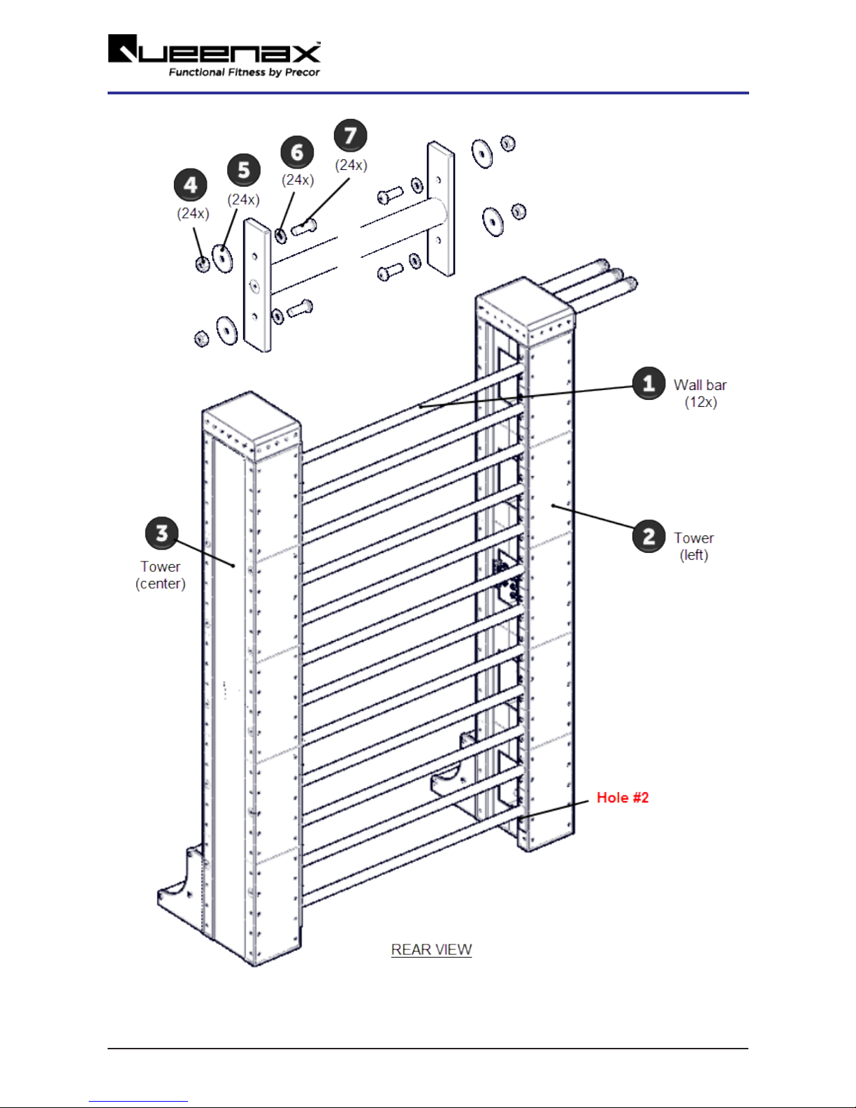
14. Install the twelve wall bar 125s between the left and center towers as shown on the rendering.
Secure using the M10 hex key bolt, M10 lock washer, M10 flat washer, and M10 nut fasteners.
Fully tighten all fasteners and torque to specification 34 ft-lbs (46 Nm). Fastener hardware
included in box with part,
15
4 Assembly and Installation
Procedure
16
4 Assembly and Installation
Procedure
ID Qty PN Description
1 3 Q40022-101 WALL BAR 125,BOX OF 4
2 1 Q2275PFY-101 TOWER - LEFT
3 1 Q2275PFY-101 TOWER - RIGHT
4 48 CWKFCN010-008 NUT,LOCK,FULL,M10,NYLON INSERT,STL,CZ
5 48 CWWNCN010-025 WASHER,FLAT,STEEL,METRIC,M10 X 40 OD X 2.5T,
CZ
6 48 CWWKCN010-019 WASHER, FLAT, STEEL, METRIC, M10 X 1.9MM
THICK, CZ
7 48 CWTECN010-030 SCREW,BHC,M10X1.5X30,CZ
Note: Part qty on a per unit basis.
Install the Easy Shelf 35s
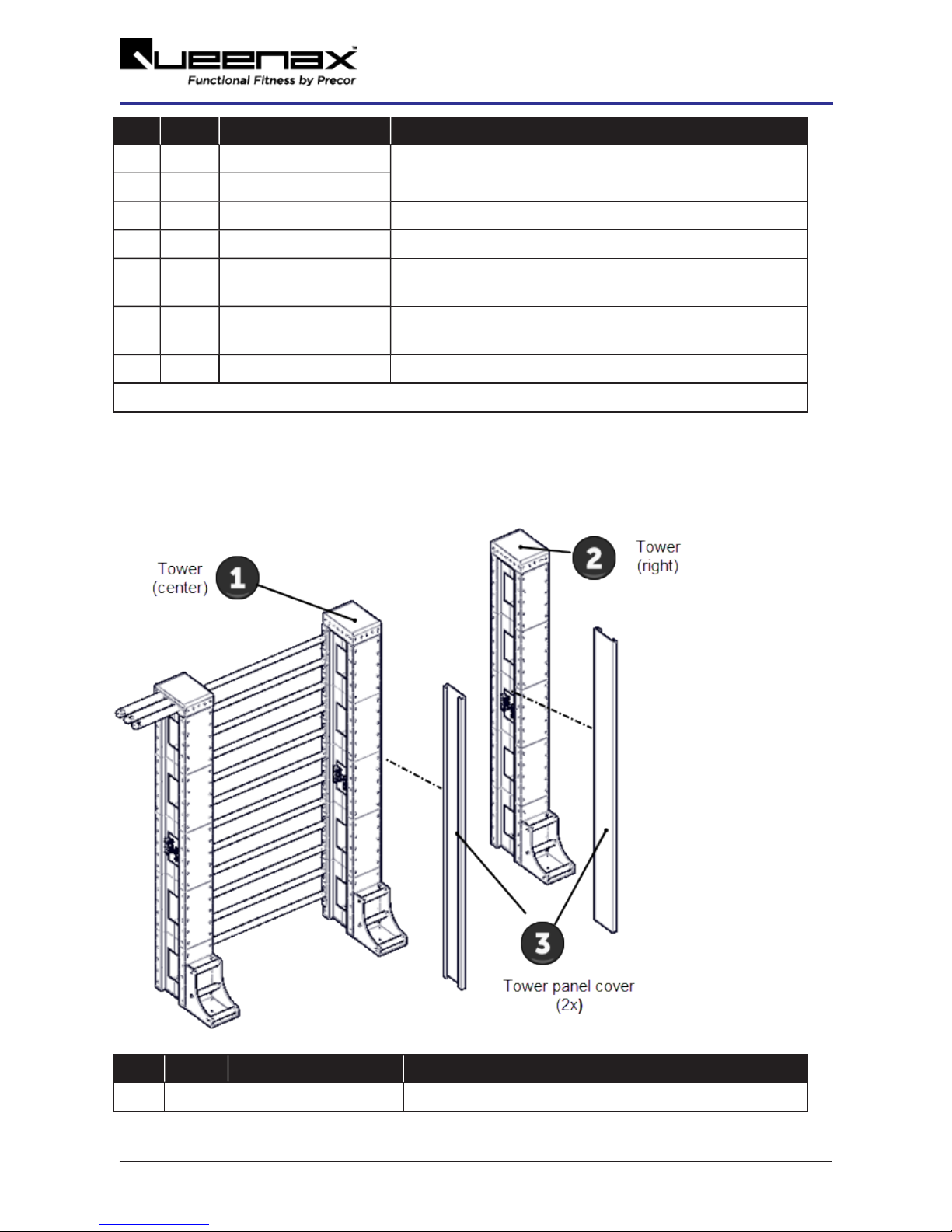
15. Install the center tower - right side tower panel cover and the right tower - left side tower panel
covers.
ID Qty PN Description
1 1 Q2275PFY-101 TOWER - CENTER
17
4 Assembly and Installation
Procedure
Table of contents
Popular Fitness Equipment manuals by other brands


G-FITNESS
G-FITNESS AIR ROWER user manual

CAPITAL SPORTS
CAPITAL SPORTS Dominate Edition 10028796 manual

Martin System
Martin System TT4FK user guide

CIRCLE FITNESS
CIRCLE FITNESS E7 owner's manual

G-FITNESS
G-FITNESS TZ-6017 user manual

Accelerated Care Plus
Accelerated Care Plus OMNISTIM FX2 CYCLE/WALK user manual


