quiko MOOVY QK-M300B User manual

E
N
G
L
I
S
H
I
T
A
L
I
A
N
O
u
s
e
a
n
d
m
a
i
n
t
e
n
a
n
c
e
m
a
n
u
a
l
MOOVY
AUTOMATIONS FOR SLIDING GATES (230/110/24V)
V07/2017

1- BEFORE INSTALLING THE AUTOMATION
Before installing the automation, you must check that:
- The wheels of the gate are attached to make the gate stable and must be in good condition;
- The entire length of the fixed rail must be free of obstacles, straight and clean and have stoppers at the
ends;
- The upper guide, must be parallel to the rail and lubricated, and it must allow for a clearance of about 1
mm from the door
Quiko Italy Sas is liable only for products it manufactures and commercializes. Once automated, the gate
becomesa machine and is therefore subject to the rules of the “ Machinery Directive”. It is on the installer to verify
its security. WARNING: Quiko Italy Sas is not liable for any damages to people, animals or things due to
unauthorised modifications, alterations or betterments on its products by third parties.
Also available in 110V. Please add “110” to the item code for 110Vac version
For 110Vac version, 230Vac in this user manual must be intended as 110Vac.

3
E
N
G
L
I
S
H
2- MATERIALS FOR INSTALLATION
FIG. 1
1. Gearmotor
2. Counterplate
3. Limit switches brackets (cammes)
4. M4 rack (NOT INCLUDED)
5. M10 Anchor bolts (NOT INCLUDED)
3- POSITIONING THE COUNTERPLATE
Dig a concrete foundation base following measurements shown on fig. 2, 3. Position the counterplate making
sure it is perfectly levelled and smooth and complying with the measurements shown on fig. 2, 3. Route the
conduits through the base holes and let them come out for at least 25 cm. If a concrete foundation base is
already available, do not unfold the anchor leaves and fasten the base only with the anchor bolts.
4- POSITIONING THE GEARMOTOR
Drill two holes ø 10 mm on the concrete in correspondence of the holes of the counterplate. Install the
anchor bolts and fasten to the concrete. Remove the gearmotor removable cover. Position the gearmotor
onto the counterplate. Temporary fasten the gearmotor to the base by tightening the anchor bolt nuts. The
gearmotor position can be adjusted horizontally of approx. 15 mm
If the anchor bolts are not available it is possible using 2 bolts M10x25. The head of the bolts shall be tack
welded to the base plate before the couterplate is embedded on the concrete
5- INSTALLING THE RACK
Use a M4 Rack. Release the gearmotor and set the gate in the open position. Place the rack on pinion
leaving at least 2 mm of gap between the gear teeth. Fasten the rack to the gate in such manner that the
bolts are in the middle of the rack slots (in this way it shall be possible adjust in the future the right gap
between the rack and pinion). Move the gate manually to secure all rack pieces along its full length. Once
the rack has been installed, finally check the gap of 2 mm between the pinion and the rack. Finally secure
the gearmotor with the nuts.

4
FIG. 3

5
E
N
G
L
I
S
H
FIG. 4
6- POSITIONING THE LIMIT SWITCHES BRACKETS (CAMMES)
FIG. 5
Manually position the gate completely open and fasten the limit switch brackets (1) (2) onto the rack so that
the limit switch lever exceeds the length of the brackets by approximately two/thirds. Repeat the operation
with gate completely closed. Provide power and carry out some opening and closing operations (see control
board user manual). Adjust the limit switch brackets so that the gate stops approximately 20 mm before the
opening and closing stops.

6
7- UNLOCKING THE MOTOR MANUALLY
FIG.6
RELEASE INSTRUCTION
In case of fault or power failure, insert the key in the lever lock and turn it of 90°CW. Pull and turn the lever
approx. 90°until it stops and the gate move manually.
WARNING: perform locking and lock release operations with motor cut off.
LOCK INSTRUCTION
To re-lock the gearmotor, return the lever in closed position and lock it and take the key away.
8- ADJUSTING THE CLUTCH (ONLY FOR QK-M2000TMODEL)
FIG. 7
With a spanner turn the adjusting bolt:
CCW for reducing the gate thrust
CW for increasing the gate thrust.
THE GATE THRUST SHALL BE ADJUSTED ACCORDING TO THE EN 12453 and 12455.

7
E
N
G
L
I
S
H
9- TYPICAL INSTALLATION
FIG. 9
CONNECTIONS CABLES
Cables section sqmm
1 POWER SUPPLY 3x1,5
2 TX PHOTOCELL ON POST 2x0,75
3 RX PHOTOCELL ON POST 4x0,75
4 TX PHOTOCELLS 2x0,75
6 RX PHOTOCELLS 4x0,75
5 KEY SELECTOR 3x1
7 FLASHING LAMP 2x1
8 AERIAL RG59
FOR THE ELECTRICAL CONNECTIONS REFER TO THE USER MANUAL OF THE CONTROL BOARD

8
GENERAL ADVICE
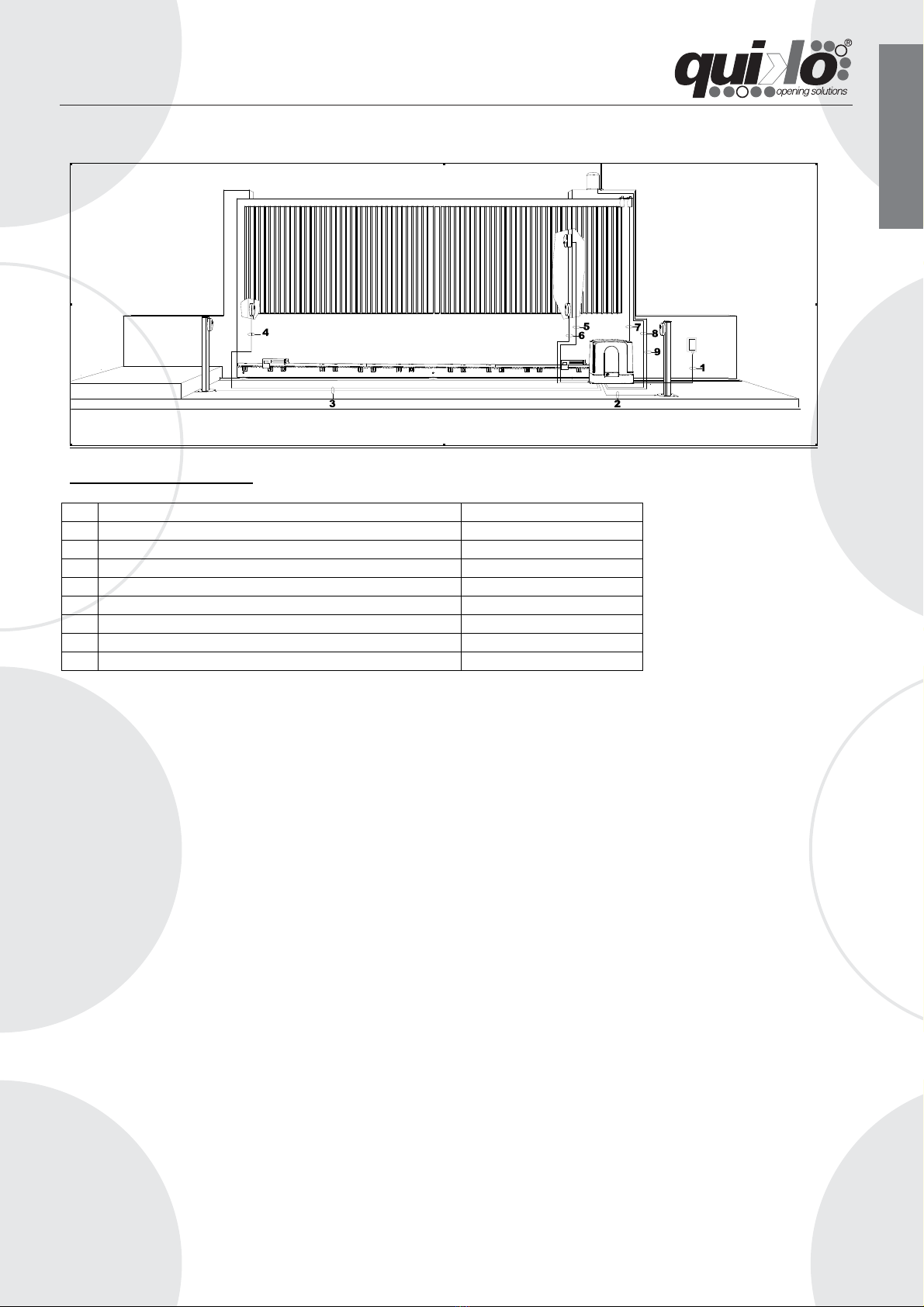
Install a gate’s safety system that complies with current regulations. Choose short routes for cables and keep
power cables separate from control ones. Install the control card in a waterproof box. Please refer to current
regulations when setting the gear motor’s maximum torque. We advice you to install an outdoor switch, in
compliance with European standards on the issue of safety, to turn the electricity off when servicing the gate.
Check that each single installed device is efficient and effective. Affix easily readable signs warning about
the presence of a motorised gate.
USE
It is absolutely forbidden to use the device for any other purposes. The installed electronic unit (which must
have built-in electric friction), allows to select the following functions:
automatic: one control impulse will open or close the gate;
semi-automatic: one control impulse will open or close the gate.
In case of a blackout, manual operation is possible by activating the unlocking device.
Having an automatic and electric power device requires special attention in a few situations:
- not to touch the device with wet hands and/or wet or bare feet;
- to turn off electricity before opening the control box and/or actuator;
- not to pull the lead to pull the plug out;
- to put the gate in movement only when it is completely visible;
- to keep out of the gate’s range of action if it is moving. Wait until it has stopped;
- not to let children or animals play near the gate;
- not to let children use the remote control or other operating devices;
- to carry out routine maintenance;
- in case of failure, to turn off electricity and operate the gate manually only if it is
possible and safe. Refrain from touching the gate and call an authorised technician.
MAINTENANCE
The MOOVY SERIES geared motors are manufactured for long-term use. Nonetheless, their normal
operation can be compromised by the conditions of the gate; therefore, we will list some operations to keep
the gate efficient.
Warning: Non-specialized staff cannot operate the gate during maintenance. You are advised to cut the
network power in order to avoid accidents or shocks. If the power must be on for various inspections, you
are advised to check and/or deactivate any possible control devices (remote controls, keyboards, etc…)
except for the devise used by the maintenance operator.
Routine maintenance
Each of the following operations must be done when needed and in all cases at least every 6 months:
Gate
Lubricate the gate’s sliding wheels;
Check the cleanliness and air-tightness of the rack.
Automation System
Check the operation of the safety devices (photo-cells, ribs, torque limiter) using the methods
described by the suppliers
Extraordinary Maintenance
If special maintenance is required for mechanical parts, you are advised to send the
gear motor out for repairs to be performed by the technicians at the manufacturer.

9
E
N
G
L
I
S
H
DECLARATION OF CONFORMITY
(OF THE MANUFACTURER)
Manufacturer: QUIKO ITALY SAS
hereby declares, under his liability, that the products:
QK-M300B, QK-M600, QK-M600B QK-M800, QK-M1200, QK-M1500, QK-M2000
are in compliance with the essential safety requirements of the regulations:
Electromagnetic Compatibility Directive .........................2004/108/EC
Low Voltage Directive ......................................................2006/95/EC
Machinery Directive .........................................................2006/42/EC
and their amendments and modifications, and with the regulations set forth by the
National Legislative Body of the country in which the machinery is destined for use.
Via Seccalegno, 19
36040 Sossano (VI)
Italia
Managing Director
Luca Borinato
Sossano, 19/10/2011

10
DECLARATION OF CONFORMITY
(OF THE INSTALLER)
The undersigned:
Address:
in charge of the set-up, declares that the product:
Gate type:
Location:
are in compliance with the essential safety requirements of the regulations:
Electro magnetic Compatibility Directive .........................2004/108/EC
Low Voltage Directive ............................................................2006/95/EC
Machinery Directive ................................................................2006/42/EC
and also declares that the related and/or specific national technical regulations have been
followed:
EN 12453/EN 12445 on Industrial, Commercial and Residential Gates and Doors – Safe
Use of Motorized Doors – Requirements and Classification – Test Methods;
EN 12604/ EN 12605 on Industrial, Commercial and Residential Gates and Doors –
Mechanical Aspects – Requirements and Classification – Test Methods;
CEI 64/8 Electrical Systems Using Nominal Tension Not Higher Than 1000V a.c. and 1500
V d.c.;
EN 13241-1 (Industrial, commercial and garage doors and gates), conformity evaluation
(6.3).
Notes:
Place and date: ………………………………………

11
E
N
G
L
I
S
H

QUIKO ITALY
Via Seccalegno, 19
36040 Sossano (VI) - Italy
Tel. +39 0444 785513
Fax +39 0444 782371
info@quiko.biz
www.quikoitaly.com
Other manuals for MOOVY QK-M300B
1
This manual suits for next models
6
Table of contents
Other quiko Garage Door Opener manuals
Popular Garage Door Opener manuals by other brands

Nice
Nice ROBO Original instructions manual and parts

Chamberlain
Chamberlain 3595S 3/4 HP owner's manual

Ducati
Ducati 8500 SF Assembly instructions

Wayne-Dalton
Wayne-Dalton Torsion 7100 Series quick start guide

CAME
CAME H SERIES manual

idomus
idomus IDO PRO (HL) MOUNTING, OPERATION AND MAINTENANCE INSTRUCTIONS