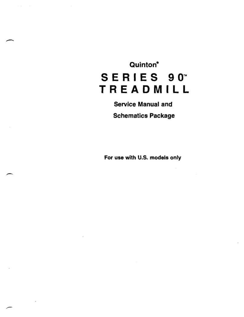
Quinton ClubTrack User manual

000377-833
033387-005 Rev New
®
TREADMILL
SERVICE MANUAL
ClubTrack
®
ClubTrack Plus
®
HR ClubTrack
c
HR ClubTrack Plus
c
MedTrack
®
CR60
MedTrack
®
SR60

Trademarks
Quinton, ClubTrack, ClubTrack Plus, and MedTrack are registered
trademarks of Quinton Instrument Company. ClubTrack 3.0,
HR ClubTrack, HR ClubTrack Plus, Hyperdrive, Q Series, and Series
90 are trademarks of Quinton Instrument Company. All other
product and company names are trademarks or registered
trademarks of their respective companies.
Service Manual
Publication Number 000377 833
Text Number 033387 005 Rev New
Copyright © 1995, 1997 Quinton Instrument Co.
All rights reserved.
Quinton Instrument Company
3303 Monte Villa Parkway, Bothell, WA 98021 8906
Telephone 425/402 2000 Fax 425/402 2001
USA and Canada:
Service: 800/426 0538
Sales: MedTrack 800/426 0347
ClubTrack 800/426 0337
Visit Quinton on the World Wide Web at
www.quinton.com
INTERNATIONAL SALES
Latin America & Asia-Pacific
Telephone 425/402-2000 Fax 425/402-2001
Europe/Hoofddorp, The Netherlands
Telephone 31-23-5672400 Fax 31-23-5672410


Preface
This manual contains information for servicing and repairing
the following Quinton
Hyperdive
™treadmills to the module level:
ClubTrack
P/N 00377
ClubTrack Plus
P/N 00382
HR ClubTrack
P/N 00402
HR ClubTrack Plus
P/N 00425
MedTrack
CR60 P/N 00380
MedTrack
SR60 P/N 00390
The manual covers domestic and international versions of the
treadmills, which are differentiated by dash numbersee
Appendix C,
Part Numbers
.
The manual is designed for Quinton-authorized service personnel
with proper training. There are no user-serviceable parts in the
treadmills. Any attempt by non-Quinton-trained personnel to
service the treadmill may void the warranty. or service
information, call Quinton Technical Service: 1-800-426-0538.
Before servicing the treadmill, read the safety requirements listed
in Appendix A.
)
Do not use this manual when servicing Series 90
, Q-Series
,
or ClubTrack 3.0
series treadmills.
Preface - iii

Contents
Preface
Overview
ClubTrack
®
.........................1-1
MedTrack
®
.........................1-1
ConfigurationPlate.....................1-2
Power............................1-2
Operation..........................1-2
Controllers .........................1-3
Theory of Operation
Overview ..........................2-1
ControllerAssembly ..................2-1
eadframeAssembly..................2-2
DeckandRollerAssembly ...............2-2
ControllerAssembly ....................2-2
Keypanel ........................2-2
UserInputs.......................2-3
OutputDisplays.....................2-3
AdditionalFunctions..................2-3
ControllertoTreadmillInterface ............2-3
RClubTrackPlusInterface ..............2-3
eadframeAssembly....................2-3
InputPowerModule ..................2-3
DriveBoard.......................2-4
DriveMotorAssembly .................2-4
GradeMotorAssemblyandSystem...........2-4
DeckandRollerAssembly .................2-4
eartRateMonitoringOption ...............2-4
Transmitter.......................2-5
Receiver.........................2-5
Microprocessor.....................2-5
Contents - v

Troubleshooting
Tools . . . . . . . . . . . . . . . . . . . . . . . . . . . . 3-1
ElectricalProblems.....................3-2
ElectronicProblems.....................3-3
Error Codes . . . . . . . . . . . . . . . . . . . . . . . 3-3
ServiceMode......................3-5
FirmwareRevision ...................3-5
ControllerKeys.....................3-5
Dislays ........................3-6
Tri-colorDislay ....................3-6
S eed/Grade (O en-Loo Mode) . . . . . . . . . . . . 3-6
HR ClubTrack Plus
™
LCDDislayTest.........3-7
TestingPinSignals...................3-7
HeartRateMonitoringOtion ...............3-8
TestingHeartRateAccuracy ..............3-9
MechanicalProblems....................3-9
WalkBelt........................3-9
DriveBelt....................... 3-10
TreadmillNoise.................... 3-10
FlowCharts........................ 3-10
Repair/Replacement and Calibration
Cautions/Warnings.....................4-1
Tools . . . . . . . . . . . . . . . . . . . . . . . . . . . . 4-2
FieldFunctionalTests ...................4-3
RemovingTreadmillHood .................4-3
Re lacing the Configuration Plate . . . . . . . . . . . . . 4-6
RelacingthePowerCord..................4-7
Re lacing the VSD Board/Card Cage Assembly . . . . . . . 4-7
RelacingtheTensioner ..................4-9
RelacingthePoly-VDriveBelt.............. 4-10
Installing the Front Shaft . . . . . . . . . . . . . . . 4-11
RelacingtheDriveMotor ................ 4-11
RelacingtheTransformer................ 4-13
RelacingtheGradeMotor................ 4-14
RelacingtheGradeMotorChain............. 4-15
Re lacing the Grade Potentiometer (POT) . . . . . . . . 4-16
GradePotWires ................... 4-16
RemovingtheRackGears ................ 4-17
ReassemblingtheRackGears .............. 4-18
RelacingaJammedRackGear.............. 4-19
RelacingthePinionShaft................ 4-21
AdjustingtheGradeLimitSwitches ........... 4-22
WalkDeckAssembly................... 4-23
Contents - vi
ReplacingtheRollers................... 4-23
ReplacingtheWalkBeltorDeck ............. 4-24
ReplacingCompressionMounts.............. 4-25
ReplacingtheDeck.................... 4-25
AdjustingtheWalkBelt ................. 4-26
WalkBelt ension .................. 4-26
WalkBelt racking.................. 4-27
ControllerAssembly ................... 4-28
RemovingtheEnclosure ............... 4-28
ReplacingthePCBA.................. 4-29
Replacing the Fluorescent ube (HR Club rack Plus) . 4-30
ReplacingtheHRReceiverAssembly......... 4-30
ConfiguringtheController .............. 4-30
RemovingtheKeypanel................ 4-31
Replacing the Controller Cable . . . . . . . . . . . . 4-31
CumulativeUse.................... 4-32
LimitedAccessSwitch ................ 4-33
CalibrationProcedures .................. 4-33
Grade Potentiometer (Grade Pot) . . . . . . . . . . . 4-33
SpeedCalibration................... 4-34
GradeCalibration................... 4-34
Preventive Maintenance
RecommendedService ...................5-1
RoutineMaintenance ...................5-1
VacuumingUnderthe readmillHood ...........5-2
ReplacementSchedules...................5-2
HeartRateMonitoringOption ...............5-2
Safety Requirements
SafetyRequirements ....................A-1
SymbolDefinitions.....................A-2
Specifications
Club rack
®
and Med rack
®
Rehabilitation readmills . . . . B-1
Club rack
®
&Med rack
®
Controllers............B-3
Club rack Plus
®
readmill (P/N 00382) . . . . . . . . . . . B-4
Club rack Plus
®
Controller (P/N 00382) . . . . . . . . . . B-5
HR Club rack Plus
TM
with Heart Rate Control (P/N 00425) . B-5
Part Numbers
FinalAssemblies ......................C-1
OperatorandServiceManuals ...............C-1
Spares . . . . . . . . . . . . . . . . . . . . . . . . . . . C-2
Contents - vii

Controllers .........................C-3
Accessories for Heart Rate Monitoring . . . . . . . . . . . C-5
Field Functional Tests
CompleteFieldFunctionalTest...............D-1
TesttheControllerDisplays ..............D-1
TesttheMultiDisplay .................D-2
TesttheController peration..............D-3
TesttheGrade peration................D-4
TestSpeed peration..................D-5
TesttheDeckFriction..................D-5
TesttheWalkBelt peration..............D-6
FieldTestNo.1.......................D-6
FieldTestNo.2.......................D-8
FieldTestNo.3.......................D-9
FieldTestNo.4...................... D-11
FieldTestNo.5...................... D-11
Assembly Drawings
........................E-1
Index
Contents - viii

Overview
ClubTrack
Quintons ClubTrack series of treadmills are motorized treadmills
with built-in controllers and are designed for fitness exercise. The
series includes the ClubTrack, P/N 00 77; HR ClubTrack with
Heart Rate Monitoring, P/N 00402; ClubTrack Plus, P/N 00 82;
and the HR ClubTrack Plus, P/N 00425. The ClubTrack Plus
provides manual and programmed operation. The HR ClubTrack
Plus adds Heart rate control, interval programming, and a
computer interface.
MedTrack
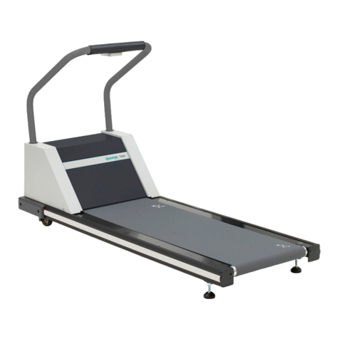
The MedTrack rehabilitation treadmills are designed for
rehabilitation exercise. Two models are available: the CR60 for
cardio-pulmonary rehabilitation (P/N 00 80) and the SR60 for
sports rehabilitation (P/N 00 90). Both feature a built-in controller.
See the Appendix of the applicable operator manual for
installation requirements.
Front of Hood
Rear
Sample Treadmill
1
Overview 1-1

Configuration Plate
Power
The circuit breaker on the front of the treadmill hood controls the
power to the treadmill. The circuit breaker must be set to
ON
for
the treadmill to run.
)
Turn off the circuit breaker before connecting or disconnecting
the treadmill from the wall outlet.
Operation
The controller, which is mounted above the front handrail, is a
computerized panel used to operate the treadmill. All commands,
including power, are entered by pressing a soft-touch key on the
panel. Visual indicators and displays show the operational status
and exercise results.
Circuit Breaker
Power Cord
Treadmills distributed for use outside
the USA and Canada have detachable
power cords.
ON
OFF
I
O
Overview 1-2

Controllers
Quinton
UP
GRADE SPEED
POWER
DOWN
STOP BELT START BELT COOL
DOWN
SELECT FASTER
SLOWER
STOP BELT
UNITS
CLEAR
ClubTrack and MedTrack SR60/CR60
CLUBTRACK
CLUBTRACK
COMPATIBLE
COMPATIBLE
TM
TM
Heart Rate Monitoring LEDs
HR ClubTrack Controller with Heart Rate Monitoring
STAGE
START BELT
NEXT
STAGE
SELECT
START
COURSE
RESUME
COURSE
COOL
DOWN
INPUT
ENTER
STOP BELT
DOWN
CLEAR
POWER
GRADE
UP
STOP BELT
SLOWER
FASTER
Quinton
FITNESS EQUIPMENT
UNITS
SPEED
ClubTrack Plus
Magnet
19296-001
PCBA 33518-001
Keypanel 3350
Controller Assy 3 506
PCBA 3 296-001
Keypanel 3 298
Controller Assy 3 297
PCBA 33519-002
Keypanel 33505
Controller Assy 3 505
Overview 1-3

STOP BELT
DOWN
UP
PREVIOUS
MENU
START BELT
F1
SPEED
UNITS
F3
F2
MENU
SLOWER
COOL DOWN STOP BELT
FASTER
GRADE
POWER
MPH
KM/H
QUINTON
FITNESS EQUIPMENT
PCBA 35452
Keypanel 35260
Controller Assy 35258
HR ClubTrack Plus Controller with Heart Rate Control
Overview 1-4

Theory of Operation
Overview
The treadmill consists of three major assemblies: controller,
headframe, and deck and roller.
Controller Assembly
The controller assembly, which is mechanically attached to the
deck, is the user interface. The user presses a key on the controller
to enter a command. The controller
processes the user-entered information
displays all exercise data
sends commands to the head frame assembly.
Power Communications
Treadmill Subassemblies
2
Theory of Operation 2-1

Headframe Assembly
The headframe assembly includes the drive and grade systems and
the electronics that drive these systems. A three-phase AC motor
drives the walk belt by supplying torque and speed to the drive
pulley through a drive belt. A DC motor drives the front of the
treadmill up and down to simulate hills. The headframe assembly
receives speed and grade commands from the controller.
Deck and Roller Assembly
The deck and roller assembly is attached to the headframe and
supports the rear of the treadmill. It provides the platform for the
walk belt. The drive belt supplies torque to the walk belt through
the drive roller pulley.
Controller Assembly
The controller assembly consists of a keypanel and PCBA mounted
in an enclosure. The enclosure which has a removable rear panel
mounts to the uprights.
Keypanel
The keypanel assembly consists of a membrane key or switch
panel and a PCBA. The keypanel and PCBA are connected through
a flexible cable that is part of the keypanel. A keypanel connector
mates to a PCBA connector.
Controller Subassemblies
Theory of Operation 2-2

User Inputs
The user enters all control commands through the keypanel. The
controller scans the membrane switches on the keypanel. The
controller PCBA interprets switch closure, updates the displayed
values, and sends control commands to the drive board.
Output Displays
The controller assembly uses LED displays mounted on the
controller PCBA. These displays show pertinent treadmill
information including target speed and grade and accumulated
e ercise information. The HR CLubTrack Plus also displays data on
an LCD screen.
Additional Functions
The controller assembly also:
performs an electronic self-test when the treadmill is turned on
provides a special mode for manufacturing and service testing
includes circuitry for the magnetic access switch.
Controller to Treadmill Interface
The controller communicates with the treadmill drive board
through a standard RS422 interface. The controller sends
commands to the treadmill drive board and receives acknowledge
and status statements from the treadmill drive board. The
controller uses 12 VDC power from the treadmill drive board as the
power source for all circuitry and for the LED displays.
HR ClubTrack Plus Interface
An RJ-45 interface connector on the rear of the HR ClubTrack Plus
treadmill permits connecting the treadmill to a computer for
e ercise monitoring. The interface complies with the industry
standard CSAFE communications protocol. Consult Quintons web
site
www.quinton.com,
Fitness Products, for an internet link to the
CSAFE specifications.
Headframe Assembly
The headframe assembly consists of the following components:
Input power module
Drive board assembly
Transformer assembly
Drive motor assembly
Grade motor assembly
Grade system consisting of a pinion shaft, rack gears, feedback
potentiometer, and limit switches.
Theory of Operation 2-3

Input Power Module
The input power module receives line power from the power outlet.
When sold for use in the United States and Canada, these
treadmills use 115 VAC power. When sold for use in Europe and
the United Kingdom, the treadmills use 30 VAC power.
Drive Board
The treadmill drive board uses line power to develop 300 VDC
which is then used to create three-phase power for the drive motor
assembly. The frequency of the three-phase signal sent to the drive
motor determines the drive motor rotational speed. The motor
current draw is a function of the torque load placed on the motor
through the deck assembly by the user.
The drive board uses 110 VAC power to generate a half wave
rectified signal used to drive the grade motor. Two solid state
relays drive the grade motor: one in the direction of increasing
grade, the other in the direction of decreasing grade.
Drive Motor Assembly
The drive motor, which is driven by the drive board, delivers
torque and speed to the front roller of the treadmill through a
poly-V belt and a set of speed reduction pulleys. A flywheel,
integral to the motor poly-V pulley, is used to average the pulsing
runner loads.
Grade Motor Assembly and System
The grade motor drives the grade pinion shaft, using a chain and a
set of speed reduction sprockets. The grade pinion shaft in turn
drives a set of rack gears, which raise and lower the front of the
treadmill.
A grade potentiometer is used to sense the actual treadmill grade
for the grade system feedback. Limit switches limit the travel of
the rack gears in the event of potentiometer failure or incorrect
calibration.
Deck and Roller Assembly
The deck and roller assembly provides the running surface for the
user. This surface consists of a movable, flexible walk belt
supported by a semi-rigid platform. The platform is supported by a
steel-welded frame.
A poly-V-belt, coupled through a pulley to the drive motor, drives
the front roller. The front roller uses friction to drive the walk belt.
A rear roller, acting as an idler pulley, tensions the walk belt. Both
rollers are mounted to the steel support structure.
Theory of Operation 2-4

Heart Rate Monitoring Option
The heart rate monitoring function is a wireless system based on
existing hardware purchased from POLAR Electro, Inc. The system
consists of a transmitter worn on the chest of the user and a
receiver mounted inside the controller enclosure. Electronics inside
the belt sense electrical energy on the s in during a heart
contraction. The transmitter emits a short electrical field burst. At
the receiver, the burst is transformed into a digital signal that is
monitored by the controller microprocessor. The microprocessor
measures the time between digital pulses, then calculates and
displays beats per minute.
Transmitter
The transmitter is imbedded inside the chest belt and begins
transmitting as soon as it detects the users heart beat.
Transmission frequency is approximately 5 Hz.
Receiver
The receiver PCBA is encased in a shoc -absorbing module.
Electrical connections to the controller PCBA comprise three wires
and a removable connector.
Reception range is approximately 3 ft (1m).
Proximity to electric motors, monitors, power supplies, T.V.,
etc. can cause directional and attenuating interference.
Microprocessor
The microprocessor calculates the heart rate and displays it in the
multifunction display.
Theory of Operation 2-5

Troubleshooting
The tables and flow charts in this chapter cover the following
potential problems:
electrical problems: power, cable connections
electronic problems: PCB, test points, signals
mechanical problems: noise, vibration, grade, speed, belts
See Chapter 4 for repair and replacement procedures.
Tools
These tools may be needed:
Phillips screwdrivers
½ inch hex socket wrench
stethoscope
Ohmmeter
High voltage is present under the hood when the treadmill is
plugged into a power source; residual high voltage remains
for a few minutes after the power is removed. Turn off the
treadmill circuit breaker, then unplug the treadmill from the
power source before removing the hood. Use extreme
caution at all times when the hood is removed.
Secure loose clothing, jewelry, and long hair before working
near treadmill parts.
Never place your fingers near rotating parts.
Do not start the walking belt when someone is on the
treadmill.
3
Troubleshooting 3-1

Electrical Problems
Use this table when:
The treadmill will not start.
There is no display on the controller.
The treadmill stops unexpectedly.
Possible Cause Action
Treadmill not plugged in Plug power cord into appropriate outlet.
Power not on Press the
Power
key on controller.
Limited access control activated,
but magnet not in place Place magnet on Quinton logo, then press
Power
twice
(off/on). To disable the control, remove magnet, then press
+
,
-
, and
Power
simultaneously.
Circuit breaker on treadmill set to
FF Set treadmill circuit breaker to N.
Building circuit breaker tripped Contact building maintenance to reset circuit breaker. If
circuit breaker trips again,
1. Check outlet voltage. If necessary, verify that the power
at the outlet and at the breaker is the correct rating for
the treadmill.
2. Verify that the power cord is not caught in the rack gear.
3. Replace the configuration plate (faulty in-rush limiter).
Power cord damaged Remove cord from outlet and replace
Blown fuse in treadmill If any of the transformer primary fuses,
F3 through F6, are blown:
1. Check the primary transformer windings for continuity
(P/N 327065-001). Should be 2 ohms or less.
2. Replace fuses and if the fuses blow again, isolate
mechanical assembly and ensure that no parts are
jammed (e.g. rack gear in grade change assembly). If F1
or F2 are blown, check the 21 Volt power supply.
Control cable between VSD* and
controller faulty Check for bent or broken pins. Replace control cable.
VSD failure Replace VSD if necessary.
Controller failure Replace controller circuit board.
Configuration plate connection
faulty Check configuration plate connections; reattach or crimp
as required. If problem persists, replace configuration plate.
Treadmill stops during run;
Stop
Belt
has not been pressed. No
error message appears
Look for loose ground wires. Reconnect and secure if loose.
LCD screen test failure Replace LCD, repeat test. If test fails again, replace PCBA.
HR ClubTrack Plus LCD does not
come on If the LEDs are on and the treadmill is functioning normally,
check the LCD connector. If problem persists, replace the
controller PCBA.
External RS232 port failure Perform loop-back test. If test fails, replace PCBA.
* VSD (variable speed drive): circuit board assembly that controls the motor
Troubleshooting 3-2

Electronic Problems
Error Codes
The treadmill performs an electronic self-test each time that it is
powered up. If a problem is detected during either power-up or
operation, an error code appears on the display. Note the code
recorded by the owner, then reference the table of error codes.
If you replace a faulty PCB Assembly, return it to the factory and
note the error code.
Code Indication Recommended Action
E001 Variable speed drive (VSD)
microprocessor chip failure Replace VSD.
E002 VSD microprocessor
EPROM/SRAM failure Replace VSD.
E00 VSD A/D failure Replace VSD.
E101 Controller PCBA
microprocessor failure Replace controller.
E102 Controller PCBA EPROM failure Replace controller.
E103 Controller PCBA interrupt
failure Replace controller.
E105 Controller PCBA NVRAM failure Re-initialize NVRAM:
1. Press
Stop
,
Faster,
and
Slower
to enter
Service Mode.
2. Press
Stop
and
Cool Down
to reinitialize.
(For HR ClubTrack Plus, press the
NV PRO-
GRAM LOAD TEST
key. Proceed to step .)
3. Press
Clear
.
. Reconfigure controller, pg -30 (HR Plus, adjust
the contrast after reconfiguring.)
If error E105 persists, replace controller.
E106 ClubTrack Plus Controller
display RAM failure Replace controller.
E201 Grade error 1. Enter service mode.
2. Calibrate POT.
3. If error persists, replace POT.
. If error persists, replace VSD.
E202 Speed error. A software check
of redundant speed variables
has indicated a disagreement
and the microprocessor will
shut down the treadmill.
Clear the error by pressing
Clear
or
Power
.
Attempt to operate the treadmill again. If error
persists, replace the VSD board.
continued
Troubleshooting 3-3
This manual suits for next models
5
Table of contents
Other Quinton Treadmill manuals

Quinton
Quinton MedTrack CR60 User manual

Quinton
Quinton ClubTrack 612 User manual

Quinton
Quinton ClubTrack 510 User manual

Quinton
Quinton ClubTrack 510 User manual

Quinton
Quinton Q55 User manual

Quinton
Quinton ClubTrack 510 User manual

Quinton
Quinton Q50 User manual

Quinton
Quinton HR ClubTrack Plus 00425 Manual

Quinton
Quinton TM55 User manual

Quinton
Quinton MedTrack CR60 User manual