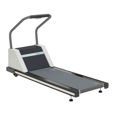
Quinton MedTrack CR60 User manual

MedTrack®CR60
Rehabilitation Treadmill
Service Manual
P/N 042101-001 Rev A

This is the CE marking of conformity indicating that
the device having this symbol on its immediate label
meets the applicable requirements of the European
Medical Device Directive.
Authorized European Representative
Medical Device Safety Service
Burckhardtstr. 1
D-30163 Hannover, Germany
Caution! Due to rapid changes in computer technology, the specifications
provided in this manual are subject to change without notice.
Trademarks
Quinton and MedTrack are trademarks or registered trademarks of
Quinton Cardiology, Inc. All other product and company names are
trademarks or registered trademarks of their respective companies.
1995, 1997, 2004 Quinton Cardiology, Inc.
All rights reserved
Publication No. 042101-001 Rev A (October 2004)
Quinton Cardiology, Inc.
3303 Monte Villa Parkway
Bothell WA 98021-8969
Telephone: 425-402-2000 Fax: 425-402-2001
Toll-free USA: 800-426-0337
For sales and technical support outside the USA, Quinton customers
should contact their local sales and technical support representative.
Visit us at www.quinton.com

MedTrack CR60 Rehabilitation Treadmill Service Manual Preface iii
Preface
This manual contains information for servicing and repairing the
Quinton®MedTrack CR60 Rehabilitation treadmill to the module level.
The manual covers domestic and international versions of the treadmill.
The manual is written for Quinton-authorized service personnel with
proper training. There are no user-serviceable parts in the treadmills. Any
attempt by non-Quinton-trained personnel to service the treadmill can
void the warranty. For service information, call Quinton Technical
Service: 800-426-0337.
Before servicing the treadmill, read the safety requirements listed in
Appendix A.
♦Use this manual only for servicing the MedTrack CR60 treadmill. Do not
use this manual for servicing other Quinton treadmills.


MedTrack CR60 Rehabilitation Treadmill Service Manual Contents v
Contents
Introduction
Overview . . . . . . . . . . . . . . . . . . . . . . . . . . . . . . . . . . . . . . . . . . . . . . . . . . . . . . . . . . . . . 1-1
Components. . . . . . . . . . . . . . . . . . . . . . . . . . . . . . . . . . . . . . . . . . . . . . . . . . . . . . . . . . . 1-2
Configuration Plate . . . . . . . . . . . . . . . . . . . . . . . . . . . . . . . . . . . . . . . . . . . . . . . . . . 1-2
Power . . . . . . . . . . . . . . . . . . . . . . . . . . . . . . . . . . . . . . . . . . . . . . . . . . . . . . . . . . . . 1-2
Operation. . . . . . . . . . . . . . . . . . . . . . . . . . . . . . . . . . . . . . . . . . . . . . . . . . . . . . . . . . 1-2
Controllers. . . . . . . . . . . . . . . . . . . . . . . . . . . . . . . . . . . . . . . . . . . . . . . . . . . . . . . . . 1-2
Theory of Operation
Overview . . . . . . . . . . . . . . . . . . . . . . . . . . . . . . . . . . . . . . . . . . . . . . . . . . . . . . . . . . . . . 2-1
Controller Assembly . . . . . . . . . . . . . . . . . . . . . . . . . . . . . . . . . . . . . . . . . . . . . . . . . 2-1
Headframe Assembly . . . . . . . . . . . . . . . . . . . . . . . . . . . . . . . . . . . . . . . . . . . . . . . . 2-1
Deck and Roller Assembly . . . . . . . . . . . . . . . . . . . . . . . . . . . . . . . . . . . . . . . . . . . . 2-2
Controller Assembly . . . . . . . . . . . . . . . . . . . . . . . . . . . . . . . . . . . . . . . . . . . . . . . . . . . . 2-2
Key Panel . . . . . . . . . . . . . . . . . . . . . . . . . . . . . . . . . . . . . . . . . . . . . . . . . . . . . . . . . 2-2
User Inputs . . . . . . . . . . . . . . . . . . . . . . . . . . . . . . . . . . . . . . . . . . . . . . . . . . . . . . . . 2-2
Output Displays. . . . . . . . . . . . . . . . . . . . . . . . . . . . . . . . . . . . . . . . . . . . . . . . . . . . . 2-3
Additional Functions. . . . . . . . . . . . . . . . . . . . . . . . . . . . . . . . . . . . . . . . . . . . . . . . . 2-3
Controller to Treadmill Interface . . . . . . . . . . . . . . . . . . . . . . . . . . . . . . . . . . . . . . . 2-3
Headframe Assembly . . . . . . . . . . . . . . . . . . . . . . . . . . . . . . . . . . . . . . . . . . . . . . . . . . . 2-3
Input Power Module . . . . . . . . . . . . . . . . . . . . . . . . . . . . . . . . . . . . . . . . . . . . . . . . . 2-3
Drive Board. . . . . . . . . . . . . . . . . . . . . . . . . . . . . . . . . . . . . . . . . . . . . . . . . . . . . . . . 2-3
Drive Motor Assembly . . . . . . . . . . . . . . . . . . . . . . . . . . . . . . . . . . . . . . . . . . . . . . . 2-4
Grade Motor Assembly and System . . . . . . . . . . . . . . . . . . . . . . . . . . . . . . . . . . . . . 2-4
Deck and Roller Assembly . . . . . . . . . . . . . . . . . . . . . . . . . . . . . . . . . . . . . . . . . . . . . . . 2-4
Troubleshooting
Diagnosis . . . . . . . . . . . . . . . . . . . . . . . . . . . . . . . . . . . . . . . . . . . . . . . . . . . . . . . . . . . . . 3-1
Tools . . . . . . . . . . . . . . . . . . . . . . . . . . . . . . . . . . . . . . . . . . . . . . . . . . . . . . . . . . . . . . . . 3-1
Electrical Problems . . . . . . . . . . . . . . . . . . . . . . . . . . . . . . . . . . . . . . . . . . . . . . . . . . . . . 3-2
Electronic Problems. . . . . . . . . . . . . . . . . . . . . . . . . . . . . . . . . . . . . . . . . . . . . . . . . . . . . 3-3
Error Codes . . . . . . . . . . . . . . . . . . . . . . . . . . . . . . . . . . . . . . . . . . . . . . . . . . . . . . . . 3-3
Service Mode. . . . . . . . . . . . . . . . . . . . . . . . . . . . . . . . . . . . . . . . . . . . . . . . . . . . . . . . . . 3-4
Enter/Exit Service Mode. . . . . . . . . . . . . . . . . . . . . . . . . . . . . . . . . . . . . . . . . . . . . . 3-4
Controller Keys. . . . . . . . . . . . . . . . . . . . . . . . . . . . . . . . . . . . . . . . . . . . . . . . . . . . . 3-4

vi Contents MedTrack CR60 Rehabilitation Treadmill Service Manual
Displays . . . . . . . . . . . . . . . . . . . . . . . . . . . . . . . . . . . . . . . . . . . . . . . . . . . . . . . . . . . 3-5
Speed/Grade (Open-Loop Mode) . . . . . . . . . . . . . . . . . . . . . . . . . . . . . . . . . . . . . . . 3-5
Speed . . . . . . . . . . . . . . . . . . . . . . . . . . . . . . . . . . . . . . . . . . . . . . . . . . . . . . . . . . . . . 3-6
Grade . . . . . . . . . . . . . . . . . . . . . . . . . . . . . . . . . . . . . . . . . . . . . . . . . . . . . . . . . . . . . 3-6
Testing Pin Signals on the Communications Cable. . . . . . . . . . . . . . . . . . . . . . . . . . 3-6
Mechanical Problems . . . . . . . . . . . . . . . . . . . . . . . . . . . . . . . . . . . . . . . . . . . . . . . . . . . . 3-7
Walking Belt . . . . . . . . . . . . . . . . . . . . . . . . . . . . . . . . . . . . . . . . . . . . . . . . . . . . . . . 3-7
Drive Belt . . . . . . . . . . . . . . . . . . . . . . . . . . . . . . . . . . . . . . . . . . . . . . . . . . . . . . . . . 3-7
Treadmill Noise. . . . . . . . . . . . . . . . . . . . . . . . . . . . . . . . . . . . . . . . . . . . . . . . . . 3-7
Flow Charts . . . . . . . . . . . . . . . . . . . . . . . . . . . . . . . . . . . . . . . . . . . . . . . . . . . . . . . . . . .3-8
Bus Voltage Flow Chart. . . . . . . . . . . . . . . . . . . . . . . . . . . . . . . . . . . . . . . . . . . . . . . 3-9
Grade Error Flow Chart. . . . . . . . . . . . . . . . . . . . . . . . . . . . . . . . . . . . . . . . . . . . . . 3-10
Drive Motor Error Flow Chart. . . . . . . . . . . . . . . . . . . . . . . . . . . . . . . . . . . . . . . . . 3-11
Communications Link . . . . . . . . . . . . . . . . . . . . . . . . . . . . . . . . . . . . . . . . . . . . . . . 3-12
Grade Problems Flow Chart . . . . . . . . . . . . . . . . . . . . . . . . . . . . . . . . . . . . . . . . . . 3-13
Repair/Replacement and Calibration
Electrical Shock . . . . . . . . . . . . . . . . . . . . . . . . . . . . . . . . . . . . . . . . . . . . . . . . . . . . . . . . 4-1
Burns . . . . . . . . . . . . . . . . . . . . . . . . . . . . . . . . . . . . . . . . . . . . . . . . . . . . . . . . . . . . . . . . 4-2
Mechanical Hazards . . . . . . . . . . . . . . . . . . . . . . . . . . . . . . . . . . . . . . . . . . . . . . . . . . . . . 4-2
Tools. . . . . . . . . . . . . . . . . . . . . . . . . . . . . . . . . . . . . . . . . . . . . . . . . . . . . . . . . . . . . . . . . 4-2
Removing the Treadmill Hood. . . . . . . . . . . . . . . . . . . . . . . . . . . . . . . . . . . . . . . . . . . . . 4-3
Replacing the Configuration Plate . . . . . . . . . . . . . . . . . . . . . . . . . . . . . . . . . . . . . . . . . . 4-5
Field Functional Test. . . . . . . . . . . . . . . . . . . . . . . . . . . . . . . . . . . . . . . . . . . . . . 4-5
Replacing the Power Cord . . . . . . . . . . . . . . . . . . . . . . . . . . . . . . . . . . . . . . . . . . . . . . . . 4-6
Hard-wired Cords (Low Voltage Units) . . . . . . . . . . . . . . . . . . . . . . . . . . . . . . . . . . 4-6
Detachable Cords (High Voltage Units) . . . . . . . . . . . . . . . . . . . . . . . . . . . . . . . . . . 4-6
Field Functional Test. . . . . . . . . . . . . . . . . . . . . . . . . . . . . . . . . . . . . . . . . . . . . . 4-6
Replacing the AC Drive Module . . . . . . . . . . . . . . . . . . . . . . . . . . . . . . . . . . . . . . . . . . . 4-6
Field Functional Test. . . . . . . . . . . . . . . . . . . . . . . . . . . . . . . . . . . . . . . . . . . . . . 4-7
Replacing the Tensioner. . . . . . . . . . . . . . . . . . . . . . . . . . . . . . . . . . . . . . . . . . . . . . . . . . 4-7
Field Functional Test. . . . . . . . . . . . . . . . . . . . . . . . . . . . . . . . . . . . . . . . . . . . . . 4-8
Replacing the Poly-V Drive Belt . . . . . . . . . . . . . . . . . . . . . . . . . . . . . . . . . . . . . . . . . . . 4-8
Field Functional Test. . . . . . . . . . . . . . . . . . . . . . . . . . . . . . . . . . . . . . . . . . . . . . 4-9
Replacing the Drive Motor. . . . . . . . . . . . . . . . . . . . . . . . . . . . . . . . . . . . . . . . . . . . . . . . 4-9
Replacing the Transformer. . . . . . . . . . . . . . . . . . . . . . . . . . . . . . . . . . . . . . . . . . . . . . . 4-10
Field Functional Test. . . . . . . . . . . . . . . . . . . . . . . . . . . . . . . . . . . . . . . . . . . . . 4-11
Replacing the Grade Motor . . . . . . . . . . . . . . . . . . . . . . . . . . . . . . . . . . . . . . . . . . . . . . 4-11
Field Functional Test. . . . . . . . . . . . . . . . . . . . . . . . . . . . . . . . . . . . . . . . . . . . . 4-13
Replacing the Grade Motor Chain . . . . . . . . . . . . . . . . . . . . . . . . . . . . . . . . . . . . . . . . . 4-13
Field Functional Test. . . . . . . . . . . . . . . . . . . . . . . . . . . . . . . . . . . . . . . . . . . . . 4-13
Replacing the Grade Potentiometer (Pot) . . . . . . . . . . . . . . . . . . . . . . . . . . . . . . . . . . . 4-13
Grade Pot Wires. . . . . . . . . . . . . . . . . . . . . . . . . . . . . . . . . . . . . . . . . . . . . . . . . . . . 4-14
Field Functional Test. . . . . . . . . . . . . . . . . . . . . . . . . . . . . . . . . . . . . . . . . . . . . 4-15
Removing the Rack Gears . . . . . . . . . . . . . . . . . . . . . . . . . . . . . . . . . . . . . . . . . . . . . . . 4-15
Reassembling the Rack Gears . . . . . . . . . . . . . . . . . . . . . . . . . . . . . . . . . . . . . . . . . 4-16
Field Functional Test. . . . . . . . . . . . . . . . . . . . . . . . . . . . . . . . . . . . . . . . . . . . . 4-17
Replacing a Jammed Rack Gear . . . . . . . . . . . . . . . . . . . . . . . . . . . . . . . . . . . . . . . . . . 4-17

MedTrack CR60 Rehabilitation Treadmill Service Manual Contents vii
Field Functional Test . . . . . . . . . . . . . . . . . . . . . . . . . . . . . . . . . . . . . . . . . . . . 4-18
Replacing the Pinion Shaft . . . . . . . . . . . . . . . . . . . . . . . . . . . . . . . . . . . . . . . . . . . . . . 4-18
Field Functional Test . . . . . . . . . . . . . . . . . . . . . . . . . . . . . . . . . . . . . . . . . . . . 4-19
Adjusting the Grade Limit Switches . . . . . . . . . . . . . . . . . . . . . . . . . . . . . . . . . . . . . . . 4-19
Field Functional Test . . . . . . . . . . . . . . . . . . . . . . . . . . . . . . . . . . . . . . . . . . . . 4-20
Walking Deck Assembly . . . . . . . . . . . . . . . . . . . . . . . . . . . . . . . . . . . . . . . . . . . . . . . . 4-20
Replacing Rollers . . . . . . . . . . . . . . . . . . . . . . . . . . . . . . . . . . . . . . . . . . . . . . . . . . . . . 4-20
Field Functional Test . . . . . . . . . . . . . . . . . . . . . . . . . . . . . . . . . . . . . . . . . . . . 4-21
Replacing the Walking Belt. . . . . . . . . . . . . . . . . . . . . . . . . . . . . . . . . . . . . . . . . . . . . . 4-21
Field Functional Test . . . . . . . . . . . . . . . . . . . . . . . . . . . . . . . . . . . . . . . . . . . . 4-22
Replacing Compression Mounts . . . . . . . . . . . . . . . . . . . . . . . . . . . . . . . . . . . . . . . . . . 4-22
Field Functional Test . . . . . . . . . . . . . . . . . . . . . . . . . . . . . . . . . . . . . . . . . . . . 4-22
Replacing the Deck . . . . . . . . . . . . . . . . . . . . . . . . . . . . . . . . . . . . . . . . . . . . . . . . . . . . 4-22
Field Functional Test . . . . . . . . . . . . . . . . . . . . . . . . . . . . . . . . . . . . . . . . . . . . 4-22
Adjusting the Walking Belt . . . . . . . . . . . . . . . . . . . . . . . . . . . . . . . . . . . . . . . . . . . . . . 4-23
Belt Tension . . . . . . . . . . . . . . . . . . . . . . . . . . . . . . . . . . . . . . . . . . . . . . . . . . . . . . 4-23
Method 1: Using Calipers. . . . . . . . . . . . . . . . . . . . . . . . . . . . . . . . . . . . . . . . . 4-23
Method 2: Without Calipers . . . . . . . . . . . . . . . . . . . . . . . . . . . . . . . . . . . . . . . 4-23
Walking Belt Tracking . . . . . . . . . . . . . . . . . . . . . . . . . . . . . . . . . . . . . . . . . . . . . . 4-24
Controller Assembly . . . . . . . . . . . . . . . . . . . . . . . . . . . . . . . . . . . . . . . . . . . . . . . . . . . 4-24
Removing the Enclosure . . . . . . . . . . . . . . . . . . . . . . . . . . . . . . . . . . . . . . . . . . . . . 4-25
Field Functional Test. . . . . . . . . . . . . . . . . . . . . . . . . . . . . . . . . . . . . . . . . . . . . . . . 4-25
Replacing the PCBA . . . . . . . . . . . . . . . . . . . . . . . . . . . . . . . . . . . . . . . . . . . . . . . . 4-25
Configuring the Controller . . . . . . . . . . . . . . . . . . . . . . . . . . . . . . . . . . . . . . . . . . . 4-26
Field Functional Test. . . . . . . . . . . . . . . . . . . . . . . . . . . . . . . . . . . . . . . . . . . . . . . . 4-26
Removing the Key Panel. . . . . . . . . . . . . . . . . . . . . . . . . . . . . . . . . . . . . . . . . . . . . 4-26
Replacing the Controller Cable. . . . . . . . . . . . . . . . . . . . . . . . . . . . . . . . . . . . . . . . 4-27
Field Functional Test. . . . . . . . . . . . . . . . . . . . . . . . . . . . . . . . . . . . . . . . . . . . . . . . 4-27
Cumulative Use. . . . . . . . . . . . . . . . . . . . . . . . . . . . . . . . . . . . . . . . . . . . . . . . . . . . 4-27
Distance. . . . . . . . . . . . . . . . . . . . . . . . . . . . . . . . . . . . . . . . . . . . . . . . . . . . . . . . . . 4-27
Time . . . . . . . . . . . . . . . . . . . . . . . . . . . . . . . . . . . . . . . . . . . . . . . . . . . . . . . . . . . . 4-27
Limited Access Switch . . . . . . . . . . . . . . . . . . . . . . . . . . . . . . . . . . . . . . . . . . . . . . 4-28
Disabling the Limited Access Switch . . . . . . . . . . . . . . . . . . . . . . . . . . . . . . . . . . . 4-28
Calibration Procedures . . . . . . . . . . . . . . . . . . . . . . . . . . . . . . . . . . . . . . . . . . . . . . . . . 4-28
Grade Potentiometer (Pot) Calibration . . . . . . . . . . . . . . . . . . . . . . . . . . . . . . . . . . 4-28
Speed Calibration . . . . . . . . . . . . . . . . . . . . . . . . . . . . . . . . . . . . . . . . . . . . . . . . . . 4-29
Grade Calibration . . . . . . . . . . . . . . . . . . . . . . . . . . . . . . . . . . . . . . . . . . . . . . . . . . 4-29
Preventative Maintenance
Recommended Service . . . . . . . . . . . . . . . . . . . . . . . . . . . . . . . . . . . . . . . . . . . . . . . . . . 5-1
Routine Maintenance. . . . . . . . . . . . . . . . . . . . . . . . . . . . . . . . . . . . . . . . . . . . . . . . . . . . 5-1
Visual Inspection. . . . . . . . . . . . . . . . . . . . . . . . . . . . . . . . . . . . . . . . . . . . . . . . . . . . 5-1
Cleaning the Treadmill Surfaces . . . . . . . . . . . . . . . . . . . . . . . . . . . . . . . . . . . . . . . . . . . 5-2
Disinfection. . . . . . . . . . . . . . . . . . . . . . . . . . . . . . . . . . . . . . . . . . . . . . . . . . . . . . . . 5-2
Vacuuming Under the Treadmill Hood . . . . . . . . . . . . . . . . . . . . . . . . . . . . . . . . . . . . . . 5-2
Frequency . . . . . . . . . . . . . . . . . . . . . . . . . . . . . . . . . . . . . . . . . . . . . . . . . . . . . . . . . 5-2
Replacement Schedules . . . . . . . . . . . . . . . . . . . . . . . . . . . . . . . . . . . . . . . . . . . . . . . . . 5-3
Electrical Testing . . . . . . . . . . . . . . . . . . . . . . . . . . . . . . . . . . . . . . . . . . . . . . . . . . . . . . . 5-3

viii Contents MedTrack CR60 Rehabilitation Treadmill Service Manual
Safety Requirements
Cautions and Warnings. . . . . . . . . . . . . . . . . . . . . . . . . . . . . . . . . . . . . . . . . . . . . . . . . . A-1
EMC Declaration Tables . . . . . . . . . . . . . . . . . . . . . . . . . . . . . . . . . . . . . . . . . . . . . . . . A-3
Symbol Definitions . . . . . . . . . . . . . . . . . . . . . . . . . . . . . . . . . . . . . . . . . . . . . . . . . . . . A-7
Specifications
MedTrack CR60 Rehabilitation Treadmill. . . . . . . . . . . . . . . . . . . . . . . . . . . . . . . . . . . B-1
Power Requirements . . . . . . . . . . . . . . . . . . . . . . . . . . . . . . . . . . . . . . . . . . . . . . . . . . . B-2
Speed Vs. Weight Range . . . . . . . . . . . . . . . . . . . . . . . . . . . . . . . . . . . . . . . . . . . . . . . . B-2
MedTrack Controller . . . . . . . . . . . . . . . . . . . . . . . . . . . . . . . . . . . . . . . . . . . . . . . . . . . B-3
Percent vs Angle Relationship for Treadmill Grade . . . . . . . . . . . . . . . . . . . . . . . . . . . B-4
Part Numbers
Final Assemblies . . . . . . . . . . . . . . . . . . . . . . . . . . . . . . . . . . . . . . . . . . . . . . . . . . . . . . C-1
Part Numbers by Category . . . . . . . . . . . . . . . . . . . . . . . . . . . . . . . . . . . . . . . . . . . . . . . C-1
Part Numbers by location. . . . . . . . . . . . . . . . . . . . . . . . . . . . . . . . . . . . . . . . . . . . . . . . C-2
Field Functional Tests
Complete Field Functional Test . . . . . . . . . . . . . . . . . . . . . . . . . . . . . . . . . . . . . . . . . . . D-1
Test A: Test the Controller Displays . . . . . . . . . . . . . . . . . . . . . . . . . . . . . . . . . . . . D-1
Test B: Test the Multi Display. . . . . . . . . . . . . . . . . . . . . . . . . . . . . . . . . . . . . . . . . D-2
Test C: Test the Controller Operation . . . . . . . . . . . . . . . . . . . . . . . . . . . . . . . . . . . D-2
Test the Controller Keys . . . . . . . . . . . . . . . . . . . . . . . . . . . . . . . . . . . . . . . . . . D-2
Test the Key Panel Displays . . . . . . . . . . . . . . . . . . . . . . . . . . . . . . . . . . . . . . . D-3
Test D: Test the Grade Operation . . . . . . . . . . . . . . . . . . . . . . . . . . . . . . . . . . . . . . D-3
Test E. Test Speed Operation. . . . . . . . . . . . . . . . . . . . . . . . . . . . . . . . . . . . . . . . . . D-3
Test F: Test the Deck Friction . . . . . . . . . . . . . . . . . . . . . . . . . . . . . . . . . . . . . . . . . D-4
Test G: Test the Walk Belt Operation . . . . . . . . . . . . . . . . . . . . . . . . . . . . . . . . . . . D-4
Test H: Shut Down the Treadmill . . . . . . . . . . . . . . . . . . . . . . . . . . . . . . . . . . . . . . D-4
Field Test No. 1 . . . . . . . . . . . . . . . . . . . . . . . . . . . . . . . . . . . . . . . . . . . . . . . . . . . . . . . D-4
Field Test No. 2 . . . . . . . . . . . . . . . . . . . . . . . . . . . . . . . . . . . . . . . . . . . . . . . . . . . . . . . D-5
Field Test No. 3 . . . . . . . . . . . . . . . . . . . . . . . . . . . . . . . . . . . . . . . . . . . . . . . . . . . . . . . D-5
Field Test No. 4 . . . . . . . . . . . . . . . . . . . . . . . . . . . . . . . . . . . . . . . . . . . . . . . . . . . . . . . D-5
Field Test No. 5 . . . . . . . . . . . . . . . . . . . . . . . . . . . . . . . . . . . . . . . . . . . . . . . . . . . . . . . D-6
Drawings
Wiring Diagrams . . . . . . . . . . . . . . . . . . . . . . . . . . . . . . . . . . . . . . . . . . . . . . . . . . . . . . .E-1
Wiring Diagram, Low Voltage Treadmill . . . . . . . . . . . . . . . . . . . . . . . . . . . . . . . . . . . .E-3
Wiring Diagram, High Voltage Treadmill . . . . . . . . . . . . . . . . . . . . . . . . . . . . . . . . . . . .E-4
Index
Index. . . . . . . . . . . . . . . . . . . . . . . . . . . . . . . . . . . . . . . . . . . . . . . . . . . . . . . . . . . . . Index-1

MedTrack CR60 Rehabilitation Treadmill Service Manual Introduction 1-1
1
Introduction
Overview
The MedTrack CR60 Rehabilitation Treadmill with a built-in controller is
designed for rehabilitation exercise.
Front
Rear

1-2 Introduction MedTrack CR60 Rehabilitation Treadmill Service Manual
Components
Configuration Plate
Power
The circuit breaker on the front of the treadmill hood controls the power
to the treadmill. The circuit breaker must be set to ON for the treadmill to
run.
WARNING!Turn off the circuit breaker before connecting or
disconnecting the treadmill from the wall outlet.
Caution! The treadmill must be on an appropriate, dedicated
electrical circuit. Nothing else should be connected to the
circuit.
Operation
The controller is a computerized panel used to operate the treadmill. It is
mounted above the front handrail. All commands, including power, are
entered by pressing a soft-touch key on the panel. Visual indicators and
displays show the operational status and exercise results.
Controllers
MedTrack CR60 Controller Panel
Circuit Breaker
Power Cord High voltage treadmills will have
detachable power cords.
Quinton
UP
GRADE SPEED
POWER
DOWN
STOP BELT START BELT COOL
DOWN
SELECT FASTER
SLOWER
STOP BELT
UNITS
CLEAR

MedTrack CR60 Rehabilitation Treadmill Service Manual Theory of Operation 2-1
2
Theory of Operation
Overview
The treadmill consists of three major assemblies: the controller, the
headframe, and the deck and roller assembly.
Controller Assembly
The controller assembly is the user interface. It is mechanically attached
to the deck. The user presses a key on the controller to enter a command.
The controller processes the user-entered information, displays all
exercise data, and sends commands to the head frame assembly.
Treadmill Subassemblies
Headframe Assembly
The headframe assembly receives speed and grade commands from the
controller. The headframe assembly includes the drive and grade systems
and the electronics that drive these systems. A three-phase AC motor

MedTrack CR60 Rehabilitation Treadmill Service Manual Theory of Operation 2-2
drives the walking belt. A DC motor drives the front of the treadmill up
and down to simulate hills. The drive motor supplies torque and speed to
the drive pulley through a drive belt.
Deck and Roller Assembly
The deck and roller assembly is attached to the headframe and supports
the rear of the treadmill. It provides the platform for the walking belt. The
drive belt supplies torque to the walking belt through the drive roller
pulley.
Controller Assembly
The controller assembly consists of a key panel and PCBA mounted in an
enclosure. The enclosure, which has a removable rear panel, mounts to
the uprights.
Controller Subassemblies
Key Panel
The key panel assembly consists of a membrane key or switch panel and a
PCBA. The key panel and PCBA are connected through a flexible cable
that is part of the key panel. A key panel connector mates to a PCBA
connector.
User Inputs
The user enters all control commands through the key panel. The
controller scans the membrane switches on the key panel. The controller
PCBA interprets switch closure, updates the displayed values, and sends
control commands to the drive board.

MedTrack CR60 Rehabilitation Treadmill Service Manual Theory of Operation 2-3
Output Displays
The controller assembly uses LED displays mounted on the controller
PCBA. These displays show pertinent treadmill information including
target speed and grade and accumulated exercise information.
Additional Functions
The controller assembly also:
• performs an electronic self-test when the treadmill is turned on
• provides a special mode for manufacturing and service testing
• includes circuitry for the magnetic access switch.
Controller to Treadmill Interface
The controller communicates with the treadmill drive board through a
standard RS422 interface. The controller sends commands to the
treadmill drive board and receives acknowledge and status statements
from the treadmill drive board. The controller uses 12 VDC power from
the treadmill drive board as the power source for all circuitry and for the
LED displays.
Headframe Assembly
The headframe assembly consists of the following components:
• Input power module
• Drive board assembly
• Transformer assembly
• Drive motor assembly
• Grade motor assembly
• Grade system consisting of a pinion shaft, rack gears, feedback
potentiometer, and limit switches.
Input Power Module
The input power module receives line power from the power outlet. The
MedTrack CR60 Rehabilitation Treadmill is available in two voltage
ranges. Low voltage units have a nominal range of 100-120 VAC. The
high voltage units have a range of 200-240 VAC.
Drive Board
The treadmill drive board uses line power to develop 300 VDC that is
then used to create three-phase power for the drive motor assembly. The
frequency of the three-phase signal sent to the drive motor determines the
drive motor rotational speed. The motor current draw is a function of the
torque load placed on the motor through the deck assembly by the user.

2-4 Theory of Operation MedTrack CR60 Rehabilitation Treadmill Service Manual
The treadmill drive board also uses AC power to generate a half wave
rectified signal used to drive the DC grade motor. Two solid state relays
drive the grade motor: one in the direction of increasing grade, the other
in the direction of decreasing grade.
Drive Motor Assembly
The drive motor, which is driven by the drive board, delivers torque and
speed to the front roller of the treadmill through a poly-V drive belt and a
set of speed reduction pulleys. A flywheel, integral to the motor poly-V
pulley, is used to average the pulsing runner loads.
Grade Motor Assembly and System
The grade motor drives the grade pinion shaft using a chain and a set of
speed reduction sprockets. The grade pinion shaft in turn drives a set of
rack gears, which raise and lower the front of the treadmill.
A grade potentiometer senses the rack gear movement for the grade
system feedback. Limit switches limit the travel of the rack gears in the
event of a potentiometer failure or incorrect calibration.
Deck and Roller Assembly
The deck and roller assembly provides the running surface for the user.
This surface consists of a movable and flexible walk belt supported by a
semi-rigid platform. This platform is supported by a steel-welded frame.
A poly-V drive belt, coupled through a pulley to the drive motor, drives
the front roller. The front roller uses friction to drive the walk belt. A rear
roller, acting as an idler pulley, tensions the walk belt. Both rollers are
mounted to the steel support structure.

MedTrack CR60 Rehabilitation Treadmill Service Manual Troubleshooting 3-1
3
Troubleshooting
Diagnosis
The tables and flow charts in this chapter cover the following potential
problems.
Electrical Problems
•Power
• Cable connections
Electronic Problems
•PCB
• Test points
• Signals
Mechanical Problems
•Noise
• Vibration
•Grade
•Speed
• Belts
Use the tables and flow charts on the following pages to diagnose
problems. See Chapter 4 for repair and replacement procedures.
Tools
The following tools may be required:
• Phillips screwdrivers
• ½-inch hex socket wrench
• Mechanical stethoscope
• Digital multi-meter
Warning! High voltage is present under the hood when the treadmill
is plugged into a power source; residual high voltage
remains for a few minutes after the power is removed. Turn

3-2 Troubleshooting MedTrack CR60 Rehabilitation Treadmill Service Manual
off the treadmill circuit breaker, then unplug the treadmill
from the power source before removing the hood. Use
extreme caution at all times when the hood is removed.
Secure loose clothing, jewelry, and long hair before
working near treadmill parts.
Never place your fingers near rotating parts.
Do not start the walk belt when someone is on the
treadmill.
Electrical Problems
Use this table when:
• The treadmill will not start.
• There is no display on the controller.
• The treadmill stops unexpectedly.
Possible Cause Action
Treadmill not plugged in. Plug power cord into appropriate outlet.
Power not on. Press the Power button on the controller.
Limited access control activated,
but magnet not in place.
Place magnet on Quinton logo, then press
Power twice (off/on). To disable the control,
remove magnet, then press +, -, and Power
simultaneously.
Circuit breaker on treadmill set to
OFF.
Set treadmill circuit breaker to ON.
Building circuit breaker tripped. Contact building maintenance to reset
circuit breaker. If circuit breaker trips again:
1. Check outlet voltage. If necessary, verify
that the power at the outlet and at the
breaker is the correct rating for the
treadmill.
2. Verify that the power cord is not caught
in the rack gear.
3. Replace the configuration plate (faulty
in-rush limiter).
Power cord damaged. Remove cord from outlet and replace.
Fuse in treadmill blown. If any of the transformer primary fuses, F1
or F2, are blown:
1. Check the primary transformer windings
for continuity. Should be 2 ohms or less.
2. Replace fuses and if the fuses blow
again, isolate mechanical assembly and
ensure that no parts are jammed (for
example, rack gear in grade change
assembly). If F1 or F2 are blown, check
the 12 volt power supply.
AC Drive Module failure. Check power supply at test points. Replace
AC Drive Module, if necessary.

MedTrack CR60 Rehabilitation Treadmill Service Manual Troubleshooting 3-3
Electronic Problems
Error Codes
Error codes provide the first means of treadmill diagnostics. The treadmill
performs an electronic self-test each time that it powers up. If a problem
is detected during either power-up or operation, an error code appears on
the display. Note the code recorded by the owner and reference the table
of error codes.
If you replace a faulty PCB Assembly, return it to the factory and note the
error code.
Controller failure. Replace controller circuit board.
Configuration plate connection
faulty.
Check configuration plate connections;
reattach or crimp, as required. Replace
configuration plate.
Treadmill stops during run but
Stop Belt button has not been
pressed. No error message
appears.
Look for loose ground wires. Reconnect
and secure, if loose.
Possible Cause Action
Code Indication Recommended Action
E101 Controller PCBA
microprocessor failure
Replace controller.
E102 Controller PCBA EPROM
failure
Replace controller.
E103 Controller PCBA interrupt
failure
Replace controller.
E105 Controller PCBA NVRAM
failure
Re-initialize NVRAM:
1. Press Stop, Faster, and
Slower to enter Service
Mode.
2. Press Stop and Cool Down to
reinitialize.
3. Press Clear.
4. Reconfigure controller, see
“Configuring the Controller”
on page 4-26.
If error E105 persists, replace
controller.
E201 Grade Error 1. Enter service mode.
2. Calibrate POT.
3. If error persists, replace POT.
4. If error persists, replace AC
Drive Module.

3-4 Troubleshooting MedTrack CR60 Rehabilitation Treadmill Service Manual
Service Mode
Enter/Exit Service Mode
The treadmill provides a service mode for troubleshooting the electronics.
To enter the service mode, press Stop Belt, Faster, and Slower
simultaneously. P000 appears in the Select display, indicating that no key
is pressed.
To exit the service mode, press and release the same three keys
simultaneously or press Power twice to power up into normal mode.
Controller Keys
To test the keys on the key panel:
E203 Motor overload caused by
one of the following:
1. Runner heavier than
weight/speed envelope.
2. Deck wear.
3. Motor lead disconnected
or loose.
4. Electrical short on the
board near the power
electronics.
5. Power electronic
component failure.
6. Motor block by
obstruction.
1. Restrict use to people within
the weight/speed
specifications.
2. Check deck wear; replace, if
necessary.
3. If the motor does not turn,
check the motor leads to
ensure all leads are
connected. One loose or
disconnected lead will cause
overload.
4. Examine board for shorts.
Examine board for blackened
components or discoloration.
5. Replace board, if damaged.
6. Remove obstructions.
E204 Communications Error. Refer to “Communications Link”
on page 3-12.
EPHI AC Drive Module ABS
voltage is too high.
Line voltage is too high.
AC Drive Module board
failure.
Refer to “Bus Voltage Flow Chart”
on page 3-9.
EPLO AC Drive Module ABS
voltage is too low.
Line voltage is too low.
Transformer connection is
bad.
Transformer failure.
AC Drive Module board
failure.
Refer to “Bus Voltage Flow Chart”
on page 3-9.
Code Indication Recommended Action

MedTrack CR60 Rehabilitation Treadmill Service Manual Troubleshooting 3-5
1. Enter the service mode. If a key has shorted out, P555 appears in the
Select display.
2. Using the table below, press each key in succession to display the
appropriate code in the Select display. P000 should reappear when
you release each key.
Displays
To test the displays on the key panel:
1. Enter the service mode.
2. Simultaneously press Stop Belt, Grade Up, and Grade Down.
3. The display cycles through one digit at a time in each display, starting
from left to right across the panel. Each digit displays the number 8
and the associated decimal point for one second, then turns off as the
next one lights up.
4. When this is completed, the LEDs light up individually, starting from
the top. The Select LEDs illuminate first, followed by the Units
LEDs.
5. After the LEDs are tested, all the digits in all three displays
simultaneously count up from 0 through 9. (No decimal points light
during this count.)
Speed/Grade (Open-Loop Mode)
In Service mode, the treadmill operates as in open-loop mode, which is
used to verify treadmill speed or grade. In this mode, the treadmill
displays the actual speed or grade, rather than the target speed or grade.
Key Code
No key pressed P000
Shorted Key(s) P555
Clear P001
Up P002
Down P003
Stop Belt P004
Input + P005
Input - P006
Select P007
Start Belt P009
Units P010
Cool Down P013
Faster P014
Slower P015

3-6 Troubleshooting MedTrack CR60 Rehabilitation Treadmill Service Manual
Speed
1. Enter the service mode.
2. Press Up, Faster, and Slower simultaneously to enter open-loop speed
mode.
3. Press Stop Belt, Faster, and Slower simultaneously to exit the service
mode (P5555 is displayed); do not press the Power key.
4. Ensure that no one is standing on the walking belt, then press Start
Belt.
5. Press and hold Faster or Slower to change the speed.
6. When testing is finished, press Clear, or press Power twice to exit
open-loop mode.
Grade
1. Enter the service mode.
2. Press Faster, Up, and Down simultaneously to enter open-loop grade
mode.
3. Press Stop Belt, Faster, and Slower simultaneously to exit the service
mode (P5555 is displayed); do not press the Power key.
4. Press and hold Up or Down to change grade.
5. When testing is finished, press Clear, or press Power twice to exit
open-loop mode.
Testing Pin Signals on the Communications
Cable
Communication cable problems can cause an E204 error message. Use an
ohmmeter to test for the following conditions:
1. Check each wire for continuity from one end of the cable to the other.
2. Check each wire for a short to another wire.
3. Check each wire for a short to the metal connector housing at the
drive end. The following table shows signals on control cable pins.
Pin No. AC Drive
Module (J12)
Pin No.
Controller (J1) Signal
1 1 T+ (Transmit+)
2 2 T- (Transmit -)
3 3 R+ (Receive+)
4 4 R - (Receive -)
5 5 GND (Ground)
66N/C
7 7 GND (Ground)
Other manuals for MedTrack CR60
1
Table of contents
Other Quinton Treadmill manuals

Quinton
Quinton Q50 User manual

Quinton
Quinton TM55 User manual

Quinton
Quinton ClubTrack 510 User manual

Quinton
Quinton ClubTrack 510 User manual

Quinton
Quinton Q55 User manual

Quinton
Quinton ClubTrack 510 User manual

Quinton
Quinton HR ClubTrack Plus 00425 Manual

Quinton
Quinton TM55 User manual

Quinton
Quinton ClubTrack User manual

Quinton
Quinton ST 55 User manual