Quinton ST 55 User manual

MEDTRACK"
ST
55
and
ST
65
TREADMILLS
SERVICE MANUAL

'SOW01
The general quality systemat QuintonInstrument
Companyhasbeen certified by BritishStandards
'<Z'
CERnFIED
Institution(BSI)to IS09001/EN 46001standards
under CertificateNumber 0357.
This is the CE markingof conformityindicatingthat the
devicehaving this symbolonits immediate label meets
oo~
the applicablerequirementsof the European-Medical
DeviceDirective.
Trademarks
Quintonand MedTrack areregistered trademarks of Quinton
Instrument Company.
All
other product and companynames are
trademarks or registered trademarks of their respective companies.
Service Manual
PublicationNumber 000378-830
Text Number 033386-001A
Copyright
O
1995Quinton Instrument Co. AU rights reserved
Quinton Instrument Company
3303Monte
Villa
Parkway,Bothell,
WA
98021-8906
Telephone206/402-2000 Fax 206/402-2001
USAand Canada: Sales 800/4260347 Service 800/4260538
INTERNATIONALSALES
Latin America
&
Asia-Pacific
Telephone206/402-2000 Fax 206/402-2005
Europe/Hoofddorp, The
etherl lands
Telephone31-2503-51514 Fax 31-2503-51660
Middle EastlDubai, U.A.E.
Telephone971-4-511491 Fax 971-4-515741

This manual containsinformationfor servicingand
repairingQuinton8MedTrackBST 55
(P/N
00378)and
ST 65
(P/N
00383)treadmills to the module level.The
manualcoversdomesticand internationalversions of the
treadmills,which aredifferentiatedby dashnumber-see
Appendix
C,
Part
Numbers.
This manual is designedforuse by Quinton-authorized
servicepersonnelwithproper training. There areno user-
serviceableparts
in
eithertreadmill.Any attemptby non-
Quinton-trainedpersonnel toservicethe equipmentmay
void the warranty.For serviceinformation, call Quinton
Technical Service: 1-800-426-0538.
Before servicingthe treadmill,read the safety requirements
listed inAppendixA.
IMPORTANT
Do not usethis manualwhen servicingSeries
90
or
Q-Seriestreadmills.

Contents
Preface
iii
1
.
Introduction
Models
......................................
1-1
Controls
....................................
1-2
Power
...................................
1-2
Operation
.................................
1-2
Emergency Stop Button
.....................
1-2
Indicators
....................................
1-2
Installation
...................................
1-2
Accessories
.................................
1-3
2
.
Theory of Operation
Overview
....................................
1-1
ECG Monitor
.............................
1
.
1
Headframe Assembly
.......................
1
.
1
Deck and Roller Assembly
...................
1
.
1
ECG Monitor to Treadmill Interface
..............
1-2
..........................
Headframe Assembly 1-2
Input Power Module
........................
1-2
Drive Board
...............................
1-2
Drive Motor Assembly
......................
1-2
Grade Motor Assembly and System
............
1-2
Deck and Roller Assembly
......................
1-3
3
.
Troubleshooting
Diagnosis
....................................
3-1
Tools
.......................................
3-1
............................
Electrical Problems 3-2
Electronic Problems
...........................
3-3
Error Codes
...............................
3-3
Mechanical Problems
..........................
3-3
Walk Belt
................................
3-3
Drive Belt
...............................
3-3
Treadmill Noise
...........................
3-4
Flow Charts
..................................
3-4
4
.
RepairIReplacementand Calibration
Warnings
Electrical Shock
...........................
4-1
Burns
....................................
4-1
........................
Mechanical Hazards
4-
1

Contents
..
-.
..
Tools
.......................................
4-2
...................
Removing the Treadmill Hood 4-3
................
Replacing the Configuration Plate 4-5
......................
Replacing the Power Cord 4-6
..........................
Hard-wired Cords 4-6
..........................
Detachable Cords 4-6
Replacing the VSD Boardcard Cage Assembly
.....
4-6
...................
BUS Recovery System (BRS) 4-7
.......................
Replacing the Tensioner 4-8
.................
Replacing the Poly-V Drive Belt 4-9
......................
Replacing the Drive Motor 4-10
......................
Replacing the Transformer 4-12
.....................
Replacing the Grade Motor 4-13
.........................
Grade Motor Chain 4-14
.........
Replacing the Grade Potentiometer (POT) 4-14
...........................
Grade Pot Wires 4-15
......................
Removing the Rack Gears 4-16
.................
Reassembling the Rack Gear 4-17
..................
Replacing a Jammed Rack Gear 4-18
......................
Replacing the Pinion Shaft 4-19
..............
Adjusting
the
Grade Limit Switches 4-20
..........................
Walk Deck Assembly 4-21
.............................
Replacing Rollers 4-21
...........................
Replacing Walk Belt 4-22
..............................
Removing Deck 4-23
...........................
AdjustingWalk Belt 4-23
..............................
BeltTension 4-23
.............................
Belt Tracking 4-24
................
Rear Roller Guard Adjustment 4-25
............
Replacing the Emergency Stop Switch 4-25
.............
Replacing the Emergency Stop Cable 4-26
.........................
Calibration Procedures 4-26
.........
Grade Potentiometer (POT) Calibration 4-26
.................
Speed and Grade Calibration 4-27
5
.
PreventiveMaintenance
.....................................
Warning 5-1
........................
Recommended Service 5-1
..........................
Routine Maintenance 5-1
..........................
Visual Inspection 5-1
..................
CleaningTreadmill Surfaces 5-1
...............................
Disinfection 5-2
...........
Vacuuming Under The Treadmill Hood 5-2
........................
Replacement Schedules 5-2
.............................
Electrical Testing 5-2
Appendix A
.
Safety Requirements
Appendix
B
.
Specifications
Contents
Appendix
C.
Part Numbers
Final Assemblies.
.............................
C-1
Spares
......................................
C-I
Appendix D. Assembly Drawings
Symbol Definitions
Index
vii

1.
Introduction
ST Treadmill
Intemational Version
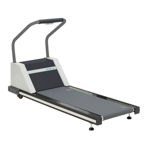
MedTrack ST medical treadmillsaredesigned specificallyfor
stress test applications.The treadmills arenot intended to
operateindependently or with a treadmillcontroller.They are
designedfor use in conjunctionwith either the Q4500 stress-test
monitor (QuintonP/N 00301)or the Q710 ExerciseMonitor
(QuintonP/N 00334).
Two MedTrackmodels are available: the ST 55 (P/N 00378) and
the ST
65
(P/N00383).Internationalversionshave a detachable
power cord and an emergencystopcontrol.
Hood
Emergency
Button
Cable
Connector

CONTROLS
-I'
Power
The treadmillmust be connected to the ECG monitor and plugged
intoa dedicated line.The treadmillcircuitbreaker, located on the
frontof the treadmill hood, must be set to
ON
and the ECG moni-
tor power mustbe on for the treadmill to operate.
NOTE
Always turn off the circuit breaker on the treadmill beforeconnecting
to or disconnectingfrom the power source.
Emergency Stop
Button Interface Power Cord
r
\
Operation
Except forthe emergencystopbutton, allcommands,including
walkbelt power, speed,grade, and protocol,areenteredfromthe
ECG monitor.All patient data appear on the monitor screen.Use
the manuals supplied with the ECG monitor to operate the tread-
../
mill and to enterservicemode.
Emergency
The treadmillmay have an emergencystopbutton located on the
Stop Button
fronthandrail: thebutton is optional
in
the U.S.A. When pressed,
thebutton stopsthebelt abruptly.
The stopbuttonis intended
onlyforemergency.
INDICATORS
Thereare no visualindicatorson the treadmill.
All
patient
responses andwarnings appear on the monitor screen.
INSTALLATION
Completetreadmill installation procedures, including site
requirements,are given in Appendix C
of
the MedTrack treadmill
operatormanuals.

ACCESSORIES
The followingaccessoriesare shippedwith eachMedTrack ST
treadmill:
Hand grip-
Operator manual (Englishlanguage)
Operatormanual (Frenchlanguage)
Operatormanual (Germanlanguage)
Operatormanual (Spanishlanguage)
Operatorm-anual (Italianlanguage)
Servicemanual (Englishlanguageonly).

Theory of
Operation
OVERVIEW
The treadmill consistsof two subassemblies: the headframe
and the deckand roller assembly. TheECG monitor, whichis
attachedby cable to the treadmill,functionsasthe user interface.
ECG
Monitor
The user entersall treadmill commandsthroughthe ECG monitor;
the informationappearsonthe monitor display. The monitor
processesthe informationand sendscommandsto the headframe
assembly.
Headframe
The headframeassembly receives speed and grade commands
Assembly
fromthe ECG monitor.The assemblyincludesthe driveand grade
systemsand the electronicsthat drivethese systems.Athree-phase
AC motor drivesthe walkbelt.
A
DC motormovesthe frontof the
treadmill up or downto simulatehills.The drivemotor supplies
torqueand speed to the drivepulley through a drivebelt.
Deckand Roller
The deckandroller assemblyis attachedto the headframeand
Assembly
supportstherear of the treadmill.It provides theplatformfor the
walking belt.The drivebelt supplies torque to thewalkbelt
through the drive roller pulley.
Support
Clinician Display
Input
4
f
Output
ECG
Monitor
Communicutions
Floor
P=l
Input,
Power
Support
Head Frame Deck and Roller
Assembly MectianicalAttachmen{ Assembly
-
Floor
LYY
I
I

Theory
of
Operation
ECG MONITOR TO TREADMILL INTERFACE
The ECG monitor communicateswith the treadmillVSD board
-
through a standard
RS422
interface.The monitor sendscommands
to theVSD board and receives acknowledgeand statusstatements
fromtheboard.
HEADFRAME ASSEMBLY
The headframeassembly consistsof the followingcomponents:
Input powermodule
Driveboard assembly
Transformer assembly
Drivemotor assembly
Grademotor assembly
Gradesystemconsistingof a pinion shaft,rack gears, feedback
potentiometer,and limit switches.
Input Power
Theinput power module receiveslinepower fromthepower out-
Module
let.All treadmills sold for use in the United Statesand Canada use
115VAC power.All units sold for use in Europe andthe United
Kingdomuse 230 VAC power. The power inputmodule also has a
connectorfor usewith the emergencystop switch: The emergency
stop switchisanoptiononunits sold in the US and Canadaand is
standard onunits sold in Europe and the United Kingdom.
Drive Board
The treadmill driveboard uses line power to develop300VDC
whichisthenused to create three-phase power forthe drivemotor
assembly.Thefrequencyof the three-phasesignalsent to the drive
motor determinesthe drivemotor rotationalspeed.The motor
current draw is a functionof the torqueloadplaced onthemotor
through the deck assemblyby the user.
The treadmill driveboard also uses llOVAC power to generatea
half wave rectified signalused to drivethe grademotor.Two solid
staterelays drivethe grade motor: one inthe directionof increas-
ing grade,the other inthe directionof decreasinggrade.
Drive Motor
The drivemotor, which is driven by the driveboard,delivers
Assembly
torqueand speed to the frontroller of thetreadmill through a
poly-V belt and a set of appropriate speed reductionpulleys. A
flywheel,integralto the motor poly-V pulley,isused to average
the pulsing runner loads.
Grade Motor
The grademotor drivesthe gradepinion shaft using a chainand a
Assembly and System
set of speedreductionsprockets.The gradepinion shaftin
turn
drivesaset of rack gears,whichraiseand lowerthe frontof the
treadmill.
Agradepotentiometersensesthe actualtreadmillgradefor the
grade systemfeedback.Limit switcheslimitthe travel of therack
gearsinthe eventof a potentiometerfailureor incorrectcalibration.
-1

Theory
of
Operation
DECK AND ROLLER ASSEMBLY
The deckand roller assemblyprovides the running surfacefor the
user. This surfaceconsistsof amovable and flexible walkbelt
supportedby a semi-rigidplatform. This platform is supported by
a steel-weldedframe.
A
poly-V belt, coupled through a pulley to the drive motor, drives
the frontroller.The front roller uses frictiontodrive the walk belt.
A
rearroller, acting as an idlerpulley, tensions the walkbelt.Both
rollers aremounted to the steel support structure.

3.
Troubleshooting
DIAGNOSIS
The tables andflow charts inthis chapter cover the following
potential problems:
electrical: power, cableconnections
electronic: error codes on
ECG
monitor
mechanical: noise,vibration, grade, speed,belts
Use the following tables andflow chartstodiagnoseproblems.
SeeChapter
4
for repair andreplacement procedures.
Tools
Thefollowing tools may be required:
Phillipsand flatbladescrewdrivers
M-inchhex wrench
stethoscope
ohmmeter
WARNING
High voltage is present under thehood when the treadmill is
plugged intoapower source;residual high voltageremains
for afewminutes afterthe power isremoved.
Turn
off the
treadmill circuitbreaker, then unplug thetreadmill fromthe
power sourcebefore removingthehood. Use extreme
caution at all times when the hood is removed.
Secureloose clothing,jewelry, and longhairbefore working
near treadmill parts.
Never placeyour fingersnear rotating parts.
Donot startthewalk belt when someone is on thetreadmill.

Troubleshootina
ELECTRICAL PROBLEMS
Treadmill Does Not Start
-
No Display
Power not on
I
Building circuitbreaker
tripped
Power cord cut
l--
Fusein treadmillblown
,
Controlcablebetweenvari-
ablespeed drive (VSD)*and
ECG monitor faulty
VSD failure
Config
-
plate
-
connectionfaulty
Optionalemergencyoff button
activated
*
VSD: the circuitboard assembly
Contactbuilding maintenance to reset circuit
breaker. If circuitbreaker trips again,
1. Check outletvoltage. If necessary,verify that
power at the outletand at thebreaker is the
correctrating for the treadmill.
2. Verify that thepower cord isnot caughtin
the rack gear.
3. Replace theconfigurationplate (faulty
in-rushlimiter).
RemoveIf anyof cordthe transformerfromoutletprimaryandreplace.fuses,F3
through F6, areblown:
1. Check theprimary transformer windings
forcontinuity(P/N327065-001). Should
be 2ohmsor less.
2. Replace fusesand if the fusesblow again,
isolatethe mechanical assemblyand ensure
that no parts arejammed (e.g.rack gear in
grade changeassembly).If F1 or F2 are
blown, check the 12Volt power supply.
Check forbent or broken pins. Replacecontrol
cable.
Check power supply attest points. Replace
VSDif necessary.
Rephce configurationplate.
Push
in
button and twist counter-clockwiseto
ud~k.
that controlsthe motor

Troubleshooting
ELECTRONIC PROBLEMS
Error Codes
Error codesprovide the firstmeansof treadmill diagnostics.The
treadmill performsanelectronic self-testeach timethat it is
powered up.If aproblemis detected during eitherpower-up or
operation,an errorcodeappears on the ECG monitor. Note the
coderecorded by the owner and referencethe table of error codes
intheECG monitor servicemanual.
If
you replacea faulty PCB Assembly return it to the factoryand
note theerrorcode.
MECHANICAL PROBLEMS
Mechanicalproblemscanincludenoise and vibration causedby
looseor worn parts.Use the followingtables to diagnosemechani-
cal failures.
Walk
Belt
Problem Action
Walk belt slipping
1.
Adjust walkbelt tension.
;
I":::::-::::
{
Walk belt not tracking Adjust tracking.
Walk belt worn out Replacewalk belt.
i
Walk deckworn out-Re lacedeck.
DriveBelt
Symptom
Squealingsound
similarto automobile
fanbelt
-or-
Walk belt slowswhen
user's foot strikesthe
deck.
Belt stopsandan
overcurrenterror
codeappears.
Possible
Cause
--
Drivemotorbelt
(poly-Vbelt)is
slipping.
1.
Stoppingthebelt
for morethan
2
secondswhen
thebelt is set to
oncan cause an
overcurrent shut-
down.
2.
The deck surface
isworn.
Action
Adjust belt
tension.
1.
Don't hold belt
longer than
2
seconds.
2.
Turn over or
replace the deck

Treadmill Noise
The followingtableprovides a diagnosticsummary of bearing
noises, alongwith other noises that may indicateproblems.
*
The type and the rate of bearing noise canhelp determine
whichbearingisat fault.The number of knocksper minute
varieswith treadmill speedbecausethe roller speedschange as
the belt speedchanges.
Possible
Cause
j
Action
Use a stethoscopewith a tube-like end, or apiece of hose about
twofeet long, toisolatebearingproblems.Hold oneend of the
hosenear the suspectedbearing, and the otherend near your
ear.Compare severalbearingstodeterminewhichis the faulty
one.
Front or rear roller
FLOW
CHARTS
Use the followingflow chartsfor step-by-steptroubleshooting.
Isolate*and replace
thumping. Rate (pulley)assembly roller.
increasesor bearings
decreaseswith
1
walkin belt s eed.
I
Squealing(similar Drivebelt loose Adjustbelt tension.
to loose automobile
Popping during Faulty elevation
ade
chan
e chain alignment
Replacebelt if
1
Adjust alignmentof

Troubleshooting
ERROR CODE FLOW CHART: EPHl
and
EPLO
BUS
voltage
/
Checkline
I
voltage.
1
BUS
voltage
Check line
voltage.
"-4'
1
voltage problern.l
v
No
Disconnect
Dower and wait
*BRS:
See
ST
headframe.
1
Yes
transformer
THEN
power up.
Check
transformer
ourput:
J7
pln
9
ond
10.
BUS
Voltage

Troubleshooting
p-pppp
--
ERROR CODE FLOW CHART: E001
Microprocessor VSD Micropro-
cessor EPROM1
RAM failure
E202
Speed Error Software
tachometer
fault
Press Power
I
1
or iear
1
pp
ed-+q
Persists
Grade Error
I
E201
I
Enter
Service
Calibrate
FI
Replace grade
Pot and
Error
(::::::.
Persists recalibrate
1
Inadvertant
Reset
Verify grounding
system
is
wired
correctlyand
is
intact
VSD
Board

Troubleshooting
ERROR CODE FLOW CHART: E204
Communications
Error
Verify
communication
cable connection
at each end.
.
Verify cable pins
are not bent or
broken or cable
damaged.
Check Ds2 on
VSD board.
Yes
-
Replace
controller.
Finished.
u
Damaged
Yes
v
Replacecable.
Error
No
Finished
onto
F1
and
F2
fuse holder base
closest to
J3.
THEN
turn on power. Measure
22
VAC
secondary.
ReplaceVSD.
I
Yes
transformer.
I I
CommunicationsLink

Troubleshooting
ERROR CODE FLOW CHART: E203
E203
Error
Overcurrent
Restrict use to
speed envelope.
No
obstructionsin disconnected
motor pulleys
CAUTION!
Disconnect
power andwait
for highvoltage
indicatorto go
resistance
between motor
leads.
Replace motor.
r-7
MotorOvercurrent
This manual suits for next models
1
Table of contents
Other Quinton Treadmill manuals

Quinton
Quinton ClubTrack 510 User manual

Quinton
Quinton HR ClubTrack Plus 00425 Manual

Quinton
Quinton ClubTrack 612 User manual

Quinton
Quinton Q50 User manual

Quinton
Quinton MedTrack CR60 User manual

Quinton
Quinton MedTrack CR60 User manual

Quinton
Quinton TM55 User manual

Quinton
Quinton Q55 User manual

Quinton
Quinton ClubTrack 510 User manual

Quinton
Quinton ClubTrack User manual