QuiQue's Aircraft Yak-54S User manual

Semi Scale Yak-54S, ARF 73”
ASSEMBLY MANUAL
Specifications
Wingspan: 73 in
Length Including Spinner: 69 in
Wing Area: 1,060 sq in
Weight (RTF): 11-12.5 lb
Radio: 4-6 Channel W/6 Servos
Recommended Engines:
2-Stroke 1.4-1.6
4-Stroke 1.4-1.80
Gas 26-30cc
1

Table of Contents
Quique’s Aircraft Company 3
Covering Colors 4
Going Over the Covering 5
Hardware Supplied 5
Additional Required Tools and Adhesives 6
Servo Selection 7
Using the Manual 7
Warning 7
Warranty Information 7
Section 1-Preparing Fuselage 8
Section 2-Horizontal Stab Installation 9
Section 3-Vertical Fin Installation 11
Section 4-Preparation and Installation of Hinges 13
Section 5-Elevator, Rudder and Aileron Control Horn Installation 15
Section 6-Rudder & Tail Wheel Installation 17
Section 7-Elevator Servo Installation 19
Section 8-Rudder Servo and Pull/Pull Installation 21
Section 9-Engine Mounting and Throttle Control Installation 24
Section 10-Landing Gear Installation 26
Section 11-Fuel Tank Installation and Engine Box Completion 28
Section 12-Engine Cowling 30
Section 13-Canopy Installation 34
Section 14-Wing Preparation and Aileron Servo Installation 37
Section 15-Battery Tray Installation 39
Section 16-Radio Equipment 40
Custom Muffler 41
Balancing the Model 42
Control Throws 43
Preflight at the Field 45
2

Quique’s Aircraft Company
3410 Saint Paris Pike
Springfield, OH 45504
Phone: (937) 629-0339
Fax: (937) 629-0335
Email: [email protected]
Website: www.Somenzini.com
www.QQAircraft.com
Online-Support:http://www.rcuniverse.com/forum/forumid_437/tt.htm
Quique and I want to express our thanks to you for choosing our 73” Yak-54 S.
We think that you will enjoy one of the best flying model aerobatic airplanes
available. It is patterned after the 37% Yak-54 which took First Place honors at
the 2003 Free Style Championships in Lakeland Florida, First Place at the Don
Lowe Master competition 2003 & 2004, First Place Tucson Shoot Out 2004 Free
Style, First Place XFC 2004, precision and free-style and Third Place at the
Tournament of Championships in Las Vegas in 2002.
Quique and I have tried to prepare the best assembly manual possible along with
best support on our line of Aircrafts. We are happy to announce that we have a
support forum on www.Rcuniverse.com that is being led by
Mr. Reza Gholamipour. Imagine, you are building your plane during weekend
when we are close and you desperately need to get answer to your question so
you can continue building, well we are happy to tell you that your question is
most likely answered on Rcuniverse forum that we handle, if not, just post your
question and have the answer in matter of hours.
Good flying to you!
Quique & Wayne
3

Covering Colors
Ultra-cote covering used on this 73” Yak-54 S can be purchased from Horizon
Hobbies Website. The codes are as follows:
Sky Blue Hanu875
Smoke Purple Hanu868
White Hanu870
Bright Yellow Hanu872
Going Over the Covering
Before beginning the assembly of your Yak-54 S, remove each part from its bag
for inspection. If you find any wrinkles in the covering, use a heat gun or covering
iron to remove them. Use caution while working around areas where the colors
overlap to prevent separating the colors. Make sure you go over the edges with
your iron as well.
4

Hardware Supplied
Pull/Pull Rudder-4 hinges Aileron-12 hinges Elevator-6 hinges
Engine Mount Wheels Wing Anti-rotation pins
Engine Cowl & landing gear Tail Wheel Elevator & Wing connecting rods
Fuel Tank Engine Box cowl mount blocks
5

Additional Required Tools and Adhesives
•Covering/Trim iron
•Xacto knife, #11 blade
•Pacer hinge glue (PT-55)
•5, 15 and 30-minute epoxy
•Petroleum jelly/Lithium grease
•Acetone/Alcohol swabs
•Felt-tip marker
•Pencil and Marker
•Ruler
•Drill
•Drill bit #1, #3, #28, #51 and #52
•Wire cutter
•Course and fine sandpaper
•Thin, medium and think C/A
•Full threaded servo mounting screws
•Sullivan inner nyrod
•Pliers
•Masking tape
•1/16” balsa strips
•Ultra fine point sharpie
•Electrical tape
•Double-sided tape
•Small sheet metal screws
•Rat-tail file
•Pin vise
•White glue such as Elmer’s Carpenter’s wood glue
•Round toothpick
•¼”x3”x3-1/4” balsa wood
•Velcro
Extensions:
•(2) 9” servo extensions for Ailerons
•(2) 24” servo extension for Elevators
•(2) 3” servo extension from receiver to Ailerons
6

Servo Selection
The servos used for the control surfaces of this Yak-54 S must have a minimum
of 130 ounce-inch of servo torque. In the prototype Yak-54 S, we used
JR8411SA on all control surfaces and on throttle we used one standard JR
servo. Best results can be obtained by using digital servos. Please do not risk
your plane by using low torque servos. This Yak-54 S has large control surfaces
and fully capable of any maneuvers that a pilot is able to perform, therefore using
weak servos will increase chance of flutter and can cause you crash.
Using the Manual
This manual is divided into sections to help make assembly easier to understand
and to provide breaks between each major section. Remember to take your time
and follow the directions.
Warning
I am sure that for the most of you this is not your first venture into the World of
flying radio controlled aircraft. For those of you that may be entering this exciting
sport early on in your modeling experience and for you with vast experience, I
think we all need to be reminded of the possible dangers that are associated with
a high performance aircraft of this type. This is not a toy. This aircraft flying at a
typical weight of ten pounds and up to one hundred miles per hour will inflect
unbelievable damage to property, life and limb. This aircraft must be flown in a
safe manner at all times. You should always do a preflight check including control
surfaces hook-ups, radio operation, (please refer to your radio equipment
instruction manual for range checks and other pertinent related information) and
all other checks relating to the safe operation of this aircraft.
Warranty Information
Quique’s Aircraft Company guarantees this kit to be free from defects in both
material and workmanship at the date of purchase. This warranty does not cover
any parts damaged by use or modification. In no case shall QQAC’s liability
exceed the original cost of the purchased kit.
7

Section 1-Preparing Fuselage
Required Tools and Adhesive
•Xacto knife, #11 Blade
•Trim Iron
•White Glue
•1/16” balsa strips
Step 1
Use a Xacto knife with a # 11 blade
and cut away the film covering on
both sides of the fuselage for the
wing openings, Figure 1.
Some modelers may want to overlap
the film covering down inside the
fuse in the opening for the wing. For
example this type of an opening for
the wing may be done as follows.
Simply cut the film about 1/8 of an
inch to the inside of the opening for
the wing. You may then bend this
extra 1/8 inch flap of film over ninety
degrees to the inside of the fuse
opening and iron it to the edge of the
balsa sheeting over the foam. Use
the trim iron for this application. Do
not touch the foam, bead board, with
your trim iron. Watch how much
heat you use here as too much will
melt the foam.
Figure 1
Step 2
Cut the film on the horizontal stab
openings, both elevator servo
openings and the slots for the rudder
cables. Please note that the elevator
servo opening on the right side of the
fuse is forward of the elevator servo
opening on the left side of the
fuselage. There is a hole on the right
side of the fuse just opposite of
opening on the left side however it is
a lightning hole and a little smaller
than a hole required for a servo.
Note: You may want to add four
pieces of 1/16 balsa strips
approximately ½ inch wide inside the
fuselage on the foam in the locations
shown in Figure 2. They are best
applied with white glue. We
mentioned this small situation to our
OEM and these areas should be
covered with some small plywood
pieces on your Somenzini Yak-54S.
Figure 2
8

Section 2-Horizontal Stab Installation
Required Tools and Adhesive
•Ultra fine point Sharpie
•Acetone
•Xacto knife, #11 Blade
•Felt tip marker
•Thin and thick C/A
Step 1
Center the H. Stab so that the left tip
and right tip are equal distance from
the fuselage sides. See Figure 3.
Figure 3
Step 2
Square up the H. Stab by measuring
the diagonal distance from the turtle
deck to the back corners (left and
right) of the H. Stab. They must be
the same distance. See Figure 4.
Figure 4
Step 3
Mark lines on both sides of the H.
Stab top and bottom with a fine felt
tip black marker, an Ultra Fine Point
Sharpie ® works well in this
application. Later when you are
ready to remove the black lines,
acetone works best.
Step 4
Remove the H. Stab from the fuse.
Mark a line, measured 1 mm on the
inside of the two lines top and
bottom that you marked along the
right and left sides of the fuse.
9

Step 5
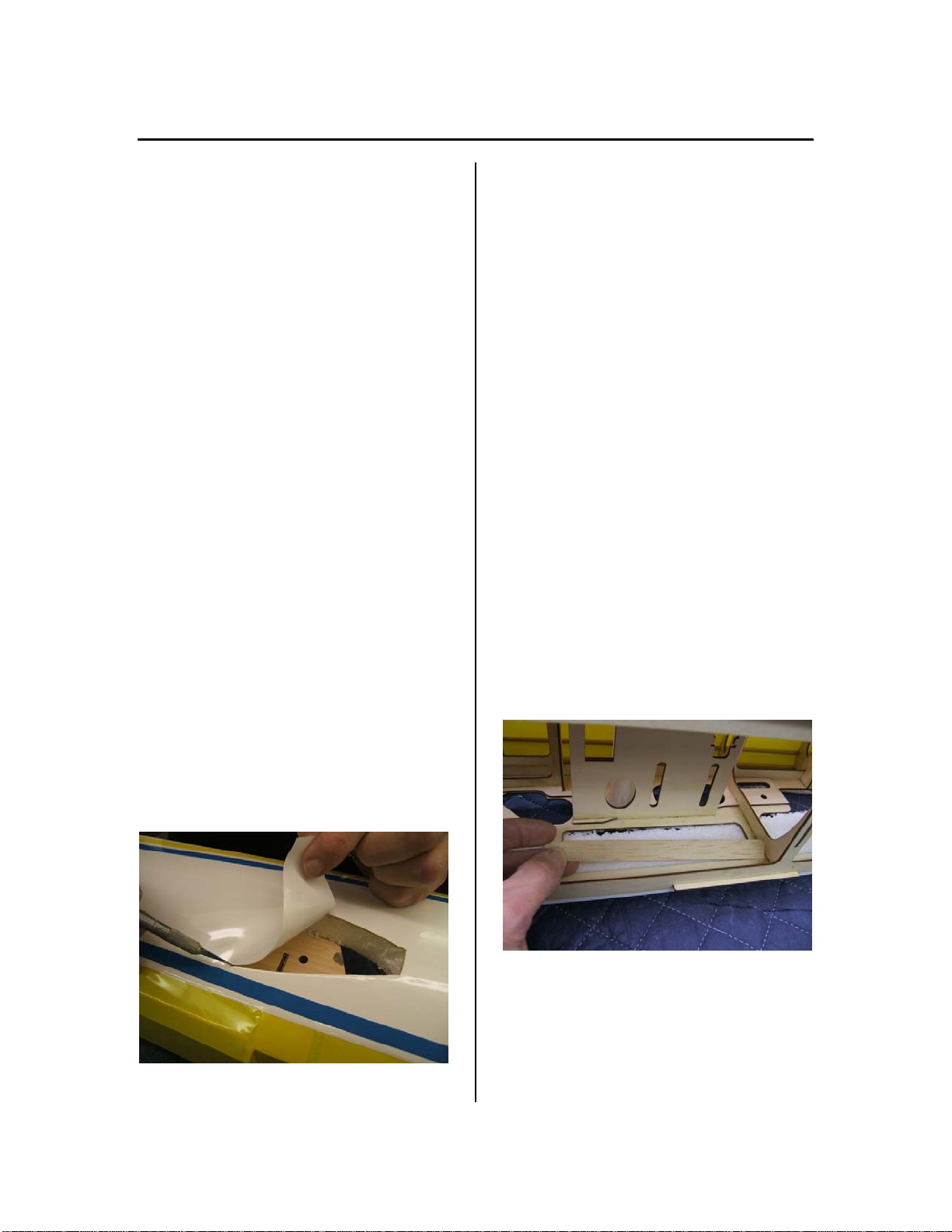
Use a new # 11 blade and gently cut
through the ultra cote. See Figure 5.
There are two layers, cut through the
top layer first and remove it. You
have probably cut through the
second layer. If not you may cut
through the second layer. Be very
careful not to cut into the balsa
sheeting as this will weaken the
structure of the Horizontal Stab as
the skin sheeting is important to its
structural integrity.
Figure 5
Step 6
Use your iron to seal down the Ultra-
cote where you removed the center
section before you make the final
attachment.
Step 7
Re-insert the H. Stab into the
fuselage. IMPORTANT: Check the
measurements again, see Figure 3 &
Figure 4 to make sure the H. Stab is
square. Before you make the final
attachment of the H. stab to the fuse,
you must check to see that the H.
stab is parallel with the wing.
To do this, you may sight down the
fuselage from the rear.
See Figure 6. Make sure you are
looking straight down the middle of
the fuse.
Figure 6
Step 8
Sight both sides of the H. stab and
compare with both sides of the wing.
If one side is lower and the other
higher, you will need to shim so both
the H. stab and the wing halves are
parallel. Our prototype needed a little
adjustment. We used a round
toothpick to wedge the one side
down a little. It was not enough so
we used another round tooth pick on
the other side of the fuse on the
opposite side to bring the H. stab
parallel with the wing. See Figure 7.
It should not take much shimming to
get it perfect. It is almost impossible
for our OEM to assemble this fuse so
that the H. stab and wing are always
parallel. You can see that the little
wedges with the round toothpicks
can correct this small problem with
very little adjustment. Now you are
ready to glue in place.
10

Section 3-Vertical Fin Installation
Figure 7
Step 9
Place the fuse so the H. Stab is
vertical so the thin C/A glue will flow
into the fuse sides.
Apply the thin C/A glue along the H.
Stab on both sides that do not have
the tooth pick wedges. Let the thin
C/A set up and then apply some
more thin C/A on the sides with the
toothpick wedges. Be careful not to
glue the toothpicks in place, as you
will of course remove them as soon
as the thin C/A sets up.
Step 10
Remove the toothpick wedges.
Apply a fillet of medium C/A over all
of the areas between the fuse sides
and the H. stab. If there is a small
gap, simply work more of the thick
C/A into the small gaps.
Required Tools and Adhesive
•Acetone
•Xacto knife, #11 Blade
•Felt tip marker
•30-minute epoxy
•Alcohol Swab/Alcohol and
paper towel
•Round toothpick
•White glue
Step 1
Insert the Vertical Fin in the fuse.
Mark a line along the V. Fin and
fuse. See Figure 8.
Figure 8
Step 2
Mark another line about ¼ or an inch
below the first line that you drew.
11

Step 3
Remove the film covering as shown.
As with the Horizontal Stab there is
more than one layer of film. By
removing the film covering you will
have a stronger bond between the
Vertical Fin and the Fuse as shown.
See Figure 9.
Figure 9
Step 4
Be careful to make a very shallow
cut through the film on the V. Fin so
you do not cut too deeply into the V.
Fin sheeting. A very sharp # 11
blade is helpful. Remove the black
ink line with acetone.
Step 5
Glue in place with 15 to 30 minute
epoxy glue. Remove any excess
epoxy with alcohol and a paper
towel.
Step 6
After epoxy hardens, check to make
sure the hinge slots between the
rudderpost and fuselage did not fill
up with epoxy. Before the epoxy
hardens, you might be able to clean
out most of the epoxy with a round
toothpick or thin piece of 1/64
plywood. The bottom hinge slots are
where the problem might occur. If
the epoxy hardens before you clean
out the hinge slots you will have a
problem. White glue could also be
used to attach the vertical fin and
clean up with water and a piece of
paper towel would be much easier.
12

Section 4-Preparation and Installation of Hinges
Required Tools and Adhesive
•Xacto knife, #11 Blade
•Lithium grease/Petroleum
Jelly
•Toothpicks
•Pacer hinge glue (PT-55) or
30-minute epoxy
The hinge slots are already installed
in the balsa hinge locations on both
the fixed surfaces and the moveable
surfaces. However they are covered
up with the covering film so they may
be a little difficult to see and locate.
Look closely and you will find the
hinge holes. I find them more easily
by running my finger along the edge
where the hinges are located. You
should feel a little depression in the
film at the opened slots under the
film.
Step 1
Use a # 11 blade to open the flat
hinge slot.
The hinge slots will have to have a
larger opening cut out just on either
side, top and bottom, of the pivot
point on both surfaces. So you will
need to open the area in the fixed
and moveable surfaces of the
ailerons, elevators and rudder.
Step 2
Use a #11 blade and make a wedge
tapered opening to accept the
pinned hinge area of the hinge. See
Figure 10 & 11.
Figure 10
Figure 11
Step 3
Make a V- cut in the fixed and
control surface area along the slot
location of the flat hinge. This
additional V- slot will insure that the
hinge will insert far enough into the
hinge slot so it is in the proper
location and provide enough depth
for the each hinge. The gap between
the flying surface and the control
surface needs to be at a minimum.
However we have to have enough of
a gap so full deflection is possible.
13

Step 4
Check the gap on each control
surface. The gap should be
somewhere between 2 and 3 mm.
This procedure will take some time
to do all of the hinges but take your
time and do a nice job. As you do
each hinge and check out the proper
depth and shape of the V-slot
necessary for each hinge, the time
involved to do each subsequent
hinge will lessen.
Before you glue the hinges in
place:
Take some lithium grease or
Vaseline and apply a very small
amount on both sides of the hinge
point on the flat hinges. Quique used
a round toothpick. See Figure 12.
This will help prevent any glue in the
pivot point.
Be very careful not to get any grease
etc. on the flat part of the hinges.
Also remember that you always glue
the hinges in to the fixed surfaces
first, let the glue harden before you
then glue in the control surfaces.
Remember to check for the correct
hinge gaps for rudder, elevators and
ailerons. You must have the correct
gap to insure the maximum control
deflection necessary for the best 3-D
aerobatics. For hinge attachment we
like to use Hinge Glue by Pacer.
You may use epoxy if you wish. If
you use epoxy, use an epoxy with a
curing time that will give you enough
time to work the hinges in place
before the epoxy hardens.
Figure 12
Step 5
Sealing the Control Surfaces
After you are done hinging the
ailerons and elevators, make sure
you seal the hinge line by using clear
ultracote. Unsealed control surfaces
may cause flutter like aileron flutter,
which may cause your plane to
crash, where sealed control surfaces
will give you better and crisper
response in flight.
For each aileron, cut ¾”x32” of clear
untracote and seal the hinge line
from bottom using a straight edge
and trim iron.
For each half elevator, cut ½”x10” of
clear unltracote and seal the hinge
line from bottom same way as you
did your ailerons.
14

Section 5-Elevator, Rudder and Aileron Control Horn Installation
Required Tools and Adhesive
•Course sandpaper
•Xacto knife, #11 Blade
•30-minute epoxy
•Alcohol Swab/Alcohol and
paper towel
Elevator Horn Installation
Step 1
Cut the slots in the bottom of the two
elevators to accept the two PC
Board elevator control horns. See
Figure 13. Notice that the slot is
located on the blue line. Again, rub
your finger over the approximately
location for the cut out to find it more
easily.
Figure 13
Step 2
Rough up the surface of the P/C
board control horn with coarse
sandpaper only where it will be glued
into the elevator.
Step 3
Then clean with alcohol or acetone
and glue in place with epoxy. Be
sure that the attachment point on the
control horn is perpendicular to the
hinge line. See Figure 14.
Figure 14
Rudder Control Horn Installation
Step 1
Find the location in the rudder where
the P/C Board rudder control horn is
to be inserted. Remove the film
covering as shown in Figure 15.
Figure 15
15

Step 2
Again rough up the surface on the
P/C board control horn that will be
glued into the rudder. Clean with
alcohol or acetone and epoxy. Be
sure that the rudder horn is square to
the rudder. You should be able to
eyeball this. See Figure 16.
Figure 16
Aileron Horn Installation
Step 1
Find the location for the aileron
servos in the bottom of each wing.
Note that the openings are in the
middle purple stripe. The location for
the aileron servo is also located in
the middle purple stripe. Note that
there are two rectangle openings
there. Use the smaller opening
available that is closest to the
fuselage. The other hole is one of
many lightening holes to keep your
Somenzini designed Yak-54 extra
light. Every little bit helps.
Step 2
Cut out the film over the servo
location hole.
Find the location on the ailerons for
the P/C Board control horn and
remove the film for both locations.
See Figure 17.
Figure 17
Note that the connecting hole on the
P/C board aileron control horn for the
connecting rod attachment should be
about 1/8 inch of an inch to the rear
of a line that is perpendicular to a
line drawn through the centerline
chord of the wing. See Figure 18,
which shows a straight edge with a
projected perpendicular line.
Figure 18
Step 3
Glue the control horns in place with 5
or 30-minute epoxy. If you work at a
slow pace, perhaps you should
choose the 30-minute.
16

Section 6-Rudder & Tail Wheel Installation
Required Tools and Adhesive
•Xacto knife, #11 Blade
•30-minute epoxy
•Alcohol Swab/Alcohol and
paper towel
•Wire cutter
You should have already prepared
all flat hinge slots for all control
surfaces. For flat hinge attachment
method, please refer again to
Section 4-Preparation and
Installation of Hinges.
Step 1
First place the plastic tail wheel
bracket on the tail wheel wire.
Step 2
Bend a 90-degree angle in the
correct direction on the tail wheel
wire that will be inserted in to a hole,
which you will soon drill into the
rudder. See Figure 19 that shows a
one inch distance from the 90-
degree bend to the bottom of the
plastic tail wheel-mounting bracket.
Figure 19
Step 3
Cut the wire that will go into the
rudder to about one inch in length.
Step 4
Cut a V-slot in the bottom of the
rudder to allow the space needed for
the tail wheel wire.
Step 5
Drill a hole in the rudder for the tail
wheel wire one inch from the bottom
of the rudder. Again please check
the v-slot in the bottom of the rudder
to make sure it will allow the hinge to
insert deep enough into the rudder.
See Figure 20.
Figure 20
Notice the hole that will accept the
tail wheel wire is just above the
hinge and the point of the Xacto
blade in this same picture.
17

Figure 21 shows the tail wheel
assembly ready for placement into
the rudder.
Figure 21
Step 6
Use the four screws provided and
attach the tail wheel bracket
assembly to the fuselage. See
Figure 22.
Figure 22
Step 7
After you have checked to make
sure all hinge slots are deep enough
and also that the V-slots are properly
cut and you have made a dry run
attachment, you may glue the hinges
into the vertical fin and fuse.
Step 8
Check the hinges for the proper
depth and allow the epoxy glue to
harden.
Step 9
Glue the rudder in place. Use
30- minute epoxy for the tail wheel
wire attachment wire that is inserted
into the rudder and also for the
hinges that will be inserted into the
rudder.
Step 10
After you have the epoxy applied,
slip the rudder onto the hinges.
Clean up any excess epoxy from all
areas with alcohol to keep hinges
from freezing up.
18

Section 7-Elevator Servo Installation
Required Tools and Adhesive
•24” servo extension
•Sullivan inner nyrod
•Pin vise
•2 full threaded servo mounting
screws
Step 1
Attach 24-inch servo extension wires
to the elevator servos. You may want
to wrap the servo plug connections
with a small piece of tape.
Step 2
To run the servo extension wires
forward, use a piece of Sullivan inner
Nyrod and place it through the oval
holes in the bottom of the fuse
formers starting from the canopy
hatch area and exiting through the
elevator servo mounting opening.
Step 3
Use a piece of tape and attach the
Nyrod to the end of the elevator
extension servo wire and gently pull
the extension through the oval holes
exiting into the canopy hatch area.
See Figure 23.
Figure 23
Step 4
Mount both elevator servos. Drill the
proper diameter holes with a pin vise
into the hardwood servo mounting
rails for the servo mounting screws.
Mount the servos so the output shaft
end of the servo is toward the front
of the fuselage.
Step 5
Attach the two extended elevator
control arms, provided, to the round
servo control arms with some small
screws. These screws are not
provided. See Figure 24.
Figure 24
19

Step 6
To attach the elevator servo control
arms to the elevator control horns,
use the titanium elevator connecting
rods, provided. The longer titanium
control rod is for the right side of the
fuse. Note that the ball links provided
should be mounted as shown in
Figure 25.
Figure 25
The ball links are mounted on the
outside of the servo arms and on the
inside of the elevator control horns.
The titanium control rods have
reverse threads for easy adjustment.
The plastic ball link connectors do
not have any threads so when you
turn the titanium connecting rods in
place you are in essence making the
threads as you make your
connections.
20
Other manuals for Yak-54S
1
Table of contents
Other QuiQue's Aircraft Toy manuals