qutools quED User manual

quED
Entanglement Demonstrator
Manual V4.0

2 quED Manual www.qutools.com
Index
Introduction and General System Description ............................................................................................3
Basic Principles of Operation........................................................................................................................... 4
Description................................................................................................................................................................ 7
Unpacking and Installation .................................................................................................................................10
Contents of Boxes .............................................................................................................................................. 10
Installation ............................................................................................................................................................. 11
Operation......................................................................................................................................................................12
Laser Safety............................................................................................................................................................ 12
Additional Warnings......................................................................................................................................... 13
Switching On......................................................................................................................................................... 14
Improving the Coupling .................................................................................................................................. 15
3.4.1 Operation of mirror mounts............................................................................................................... 15
3.4.2 Realignment of the setup .................................................................................................................... 16
3.4.3 Full Alignment Procedure..................................................................................................................... 17
Checking the Entanglement Quality (quick procedure)................................................................. 19
Troubleshooting ........................................................................................................................................................20
Improving the Entanglement Quality...................................................................................................... 20
High single count rates but very view coincidences........................................................................ 23
4.2.1 There is polarization contrast in both arms............................................................................... 23
There is no polarization contrast in at least one arm ..................................................................... 23
Experiments with the quED................................................................................................................................24
Measurement of correlation curves ......................................................................................................... 25
Bell state discrimination................................................................................................................................. 26
Bell experiment.................................................................................................................................................... 26
Tomographic reconstruction of the two-photon density matrix............................................. 29

www.qutools.com quED Manual 3
Introduction and General System Description
The quED is a complete system for the generation and analysis of polarization-entangled
photon pairs. In its basic version the quED delivers the coincidence counting rate of above 1 kHz
with at least 90%visibility of correlation curves in two complementary bases. These
parameters guarantee that the genuine two-particle entanglement can be detected and
demonstrated, e.g. via measurement of Bell inequalities, within few minutes after the start of
the system.
The heart of the quED employs a spontaneous parametric down-conversion process to
generate polarization-entangled photon pairs. Fiber coupled single photon detectors in
connection with polarizing filters are used to detect the photon pairs, analyze their polarization
and verify their non-classical polarization correlations. The quED control unit features a laser
diode driver and a multi-channel counter with integrated coincidence logic electronics, which
registers single photon detections and photon pair detections. The corresponding counting
rates are displayed on an integrated display or can be read out via a network (http://) interface.
This document contains user information for the optical unit of quED, i.e. the source of
polarization entangled photon pairs. Please read the manual carefully before operating the
source. Particular attention should be paid to the section of laser safety. For the details on
description and operation of quED control unit users are referred to the document “Down-
conversion Controller Manual”.

4 quED Manual www.qutools.com
Figure 1: Spatial distribution of the down-conversion emission for type I phase matching. The
transverse momentum conservation requires that down-conversion photons have to emerge
from the crystal along the directions lying always on exactly opposite sides of the cone.
Basic Principles of Operation
To generate entangled photon pairs, a second-order nonlinear process, usually referred to as
spontaneous parametric down-conversion (SPDC), is used in the quED. In the SPDC process
photons of an intense laser pump beam spontaneously convert in a nonlinear crystal with a
very low probability (≈ for standard materials) into pairs of lower-frequency photons. Due
to energy and momentum conservation in the nonlinear interaction the possible wavelengths
and emission directions of the generated photons are severely constrained. Consequently, the
emission pattern is formed by cones, which imprint the characteristic rings in the plane (P)
perpendicular to the pump-beam direction. In type I phase matching the cones are concentric
around the pump direction, as illustrated in Figure 1. Every cone corresponds to a distinct
emitted wavelength. The opening angles of the emission cones thus depend on the
wavelengths of the emitted photons, but also on the angle between the pump direction and
the optical axis; (the smaller the angle , the smaller the opening of the cone with a given
wavelength). This allows to angle tune the spatial emission of down-conversion photons as
required.

www.qutools.com quED Manual 5
To obtain polarization entanglement from SPDC, the quED utilizes a well-known method of
coherent spatial overlap of the emissions from two adjacent type-I crystals. Consider two non-
linear crystals, both operated in type-I phase-matching configuration and pumped with linearly
polarized light. The otherwise identical crystals are oriented such that their optical axes lie in
mutually perpendicular planes. For example, let the optical axis of the first crystal be aligned in
the vertical plane and the axis of the second crystal in the horizontal plane. Due to the type- I
coupling, the down-conversion process occurs only in the crystal, where the pump photon is
extraordinary polarized, emitting two ordinary polarized down-conversion photons into the
characteristic cone. That is, with the vertically-polarized pump the down-conversion process
occurs only in the first crystal emitting pairs of horizontally polarized photons, whereas with
the horizontally-polarized pump it occurs only in the second crystal producing two vertically-
polarized photons. By pumping the crystals with light, linearly polarized at 45° with regard to
horizontal and vertical direction, there is an equal probability that a pump photon will be down-
converted in either crystal. Provided that the two emission processes are coherent with one
another, which is fulfilled as long as there is no way of ascertaining whether a photon pair was
produced in the first or the second crystal, the following entangled state is automatically
generated:
The symbols |and |represent the horizontal and vertical polarization state of photons
and the labels and correspond to the two spatial modes, which are in practice selected
by e.g., pinholes or fibers. The relative phase is determined by the details of the phase
matching and thickness of the crystals but can be controlled by adjusting the relative phase
between the horizontal and vertical components of the pump light.
The distinguishing information, which might possibly label the emission processes and thereby
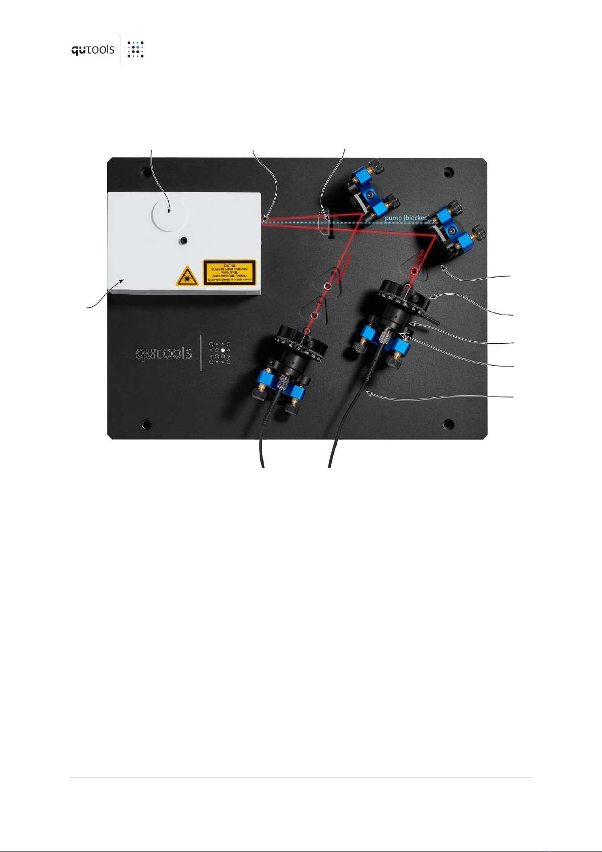
reduce their mutual coherence, can be either of temporal or spatial character. The latter case
occurs whenever the emission modes from the two crystals are spatially distinguishable. To
avoid this situation, the nonlinear crystals have to be thin enough and the down-conversion
photons have to be collected into spatially single-mode channels, such as a pair of single- mode
fibers. The use of thin crystals ensures that the emission cones from the two crystals overlap to
a great extent. Moreover, the single-mode nature of the collection modes re- moves practically
all the spatial information the photons may have carried before entering the fiber.
Consequently, there is even in principle no way how to spatially distinguish whether the down-
conversion photons are coming from the first or the second crystal and therefore pure
polarization-entangled photon pairs can be detected.

6 quED Manual www.qutools.com
In the time domain, the crystal birefringence in combination with dispersion lead to an un-
wanted effect as well. The arrival times of photons at the output face of the second crystal
depend on their wavelengths and polarizations, which reveal the actual position of the photon-
pair’s origin. This leads to a partial loss of coherence between the two emission processes, and
thus to the reduced entanglement quality. The detrimental temporal effect is two-fold, which is
illustrated in a simplified fashion in Figure 2. First, it is primarily the group-velocity mismatch
between the pump and the down-conversion light, which causes the photon pairs born in the
first crystal to be advanced with regard to those originating from the second crystal. This is
usually precluded using a continuous-wave pump laser. Since a (spectrally broadband) free-
running blue laser diode is used as the pump in the quED, a special birefringent crystal has to
be included in the path of the pump beam. It introduces a proper temporal retardation
between its horizontally and vertically polarized components and thus effectively pre-
compensates the effect. Second, the dispersive delay of the down-conversion photons at non-
degenerate wavelengths are different for the two emission possibilities, because the photons
generated in the first crystal acquire an extra spread by propagating through the second
crystal; (since the type I SPDC emission is spectrally very broadband, the detection of photons
with very non-degenerate wavelengths is indeed possible in the quED).
Figure 2: Explanation of the detrimental time effect inherent to SPDC emission in a two-crystal
configuration. Due to crystal birefringence and dispersion, the arrival times of non- degenerate
photons at the output face of the second crystal (2) differ in general for the two
emission possibilities. The photon pairs from the first crystal (1) are advanced with regard to
photon pairs from the second
.Moreover, the photons originating from the first
crystal experience higher dispersive delay due to their pass through the second crystal
. Consequently, a compensation using two additional birefringent crystals erasing
their temporal distinguishability has to be applied.

www.qutools.com quED Manual 7
Therefore, an additional birefringent crystal has to be put behind the down-conversion crystals
to counteract this second effect, too. The described double-crystal compensation technique
ensures a complete temporal indistinguishability of the emission processes even though a free-
running laser diode as a pump source is used and no spectral filtering of generated photons is
applied in the quED.
Description
Referring to Fig. 3, there is shown the source for the generation of polarization-entangled
photon pairs. For convenience, the whole optical set-up mounted on an aluminum breadboard
can be divided into two basic blocks: the pump-beam block and the down-conversion block. All
the components of the pump assembly are installed on a rectangular pedestal. This block
comprises a laser diode head, two mirrors, beam-shaping optics, two half-wave retarder, a pre-
compensation birefringent crystal, and nonlinear down-conversion crystals. The blue laser
diode is built in the laser diode mount. The mount features a protective circuit to maximally
eliminate laser diode failures due to electrostatic discharge and a thermoelectric module to
precisely regulate the operating temperature of the diode. The strongly divergent light from the
laser diode is focused using a telescope consisting of a collimating aspheric lens and a negative
spherical lens.

8 quED Manual www.qutools.com
Polarizer in
rotating mount
Longpass filter
Fiber coupler
PM fiber
Pump and
source
Figure 3: Architecture of the quED optical setup for the generation and collection of
polarization-entangled photon pairs. The pump laser and the actual crystal source is hidden
under the white cover for laser safety reasons. More details are displayed in
Figure 4.
Waveplate
Longpass filter
(pump block)
Slot for
alignment plate
Beam folding
mirror

www.qutools.com quED Manual 9
Figure 4: Inner details of the pump assembly with the nonlinear crystal.
The angle of linearly polarized laser light emitted from the laser diode is adjusted with the half-
wave plate. This have-wave plate can be inserted rotated by 180° to manipulate the down-
converted state. In the default position the pump laser enters through the circular aperture on
the back. The nonlinear down-conversion crystals are mounted at the focus of the laser beam.
Additionally, a pinhole with two adjacent crosses is mounted in the pump beam path. This
enables the realignment from scratch in case the couplers completely lost signal (see Figure 8).
All the components of the down-conversion block are positioned along the two down-
conversion emission directions and form two arms. Either arm comprises a mirror, a rotatable
polarizing filter optionally motorized, a long-pass filter, an adjustable optical coupler and a
polarization maintaining (PM) single-mode fiber (12). Long-pass filters are inserted into the
paths of down-conversion photons to block the residual laser-diode light and stray light.
Alignment
Target
Wave Plate
(parking Position)
Pre-/ post
Compensation
Crystals
BBO Crystal
Mirrors
Lens
neg. focal length
Laser Diode and
Collimation

10 quED Manual www.qutools.com
To verify the entanglement of down-conversion photons a pair of polarization filters is used.
Both the mirror and the coupler are held in kinematic mounts allowing the fine angular
alignment of the coupling mode, which is defined by the single-mode fiber. The full control over
the orientation and the divergence of the coupling mode is imperative to achieve high coupling
efficiencies of down-conversion photons into single-mode fibers. In either arm the iris
diaphragm (8) with adjustable opening is positioned between the mirror and the polarization
filter. For additional information on the alignment procedure, we refer to sections 3.4.2 and
3.4.3. The fiber-coupled down-conversion photons are detected using passively quenched
silicon avalanche photo diodes hidden in the quCR electronic control unit. The corresponding
single detection rates in both arms and the coincidence count rate are displayed on the counter
panel of this unit. To prevent the escape of laser radiation and to prevent personnel access to
the laser beam during normal operations, the pump assembly is housed in a protective
enclosure. The enclosure can be removed when the operator needs to perform maintenance or
adjustment tasks. This is required for example during full alignment procedure described in
section 3.4.3. The front output aperture of the protective enclosure contains the a long-pass
filter which acts as a beam block for the pump laser. Please verify periodically that this filter is in
place and intact. Otherwise, high power laser radiation can escape the housing and potentially
cause harm or damage.
Unpacking and Installation
Contents of Boxes
When you have received the product, please make sure that the following parts are included:
•Box 1: Optics part
oAluminum breadboard with source, mirrors, couplers and polarizers in rotating
mount.
o2 polarization maintaining fibers attached to the couplers. These fibers should
never be unplugged.
o2 long pass filter caps in front of the couplers.
oalignment plate (only to be installed during a full alignment procedure (see
Figure 8 and section 3.4.3).
oOptical fiber checker
oCable with with SUB-D9 connectors (to connect down-conversion source with
control unit)

www.qutools.com quED Manual 11
Installation
Before installing the system, make sure that you are familiar with and
have obeyed all necessary laser safety precautions. Please refer to
paragraph 3.1 for this purpose. Handle the source and all its components
very gently. Especially, do not tilt the breadboard too far and be very
careful with electrostatic discharges in the immediate vicinity of the laser
diode. For additional warnings please see the relevant section (3.2) of the
manual.
Please follow these steps:
1. Optionally: Remove the source from the plastics box. It is fastened to the box with four
screws in the corners of the aluminum breadboard. Remove the screws from the top.
Gently put the breadboard with the source on a stable table. In case you decide to
operate the source in the box, make sure to avoid any damage to the fibers when
closing the lid.
2. Place the control unit next to the breadboard and connect it to a power socket.
3. Connect the quED with the control unit using the SUB-D9 connector cable.
4. After removing the protective caps, plug and fasten the FC/PC connectors of the single
mode fibers into the optical inputs of the control unit (see also Figure 5).

12 quED Manual www.qutools.com
Operation
Laser Safety
This product contains Class 3B laser according to IEC 60825-1 (or EN 60825-1) Safety Standards.
Figure 5: The fiber connector is correctly inserted into the optical fiber input of the twin
detection module only if the keyway on the fiber receptacle mates with the positioning key on
the fiber connector.
Class 3B lasers are hazardous to the eye from direct beam viewing, and
from specular reflections even for short and unintentional exposures!
Therefore, it is absolutely necessary to take overall safety measures
when operating the source.
The quED should be operated in a restricted area equipped with post warning signs to alert
those present. To ensure adequate warning of hazards associated with the accessible laser
radiation, relevant warning signs and labels are conspicuously affixed to the quED. When
removing the protective laser enclosure, always wear suitable safety glasses to prevent
exposure to laser light. For additional information users should refer to appropriate documents
specifying the safety standards such as IEC 60825-1 “Safety of laser products –Part 1:
Equipment classification and requirements”.

www.qutools.com quED Manual 13
Additional Warnings
The following precautions should be thoroughly reviewed and followed to avoid the risk of any
damage or failure.
•Avoid any back-reflection into the aperture of the laser head. Permanent damage to the
laser diode can occur.
•Never connect or disconnect the cable between the control unit and the source while
the laser is switched on. These acts can lead to laser hazard for the operator and
possible permanent damage to the laser diode.
•The lifetime of the laser diode can be significantly shortened by applying the driving
currents higher than the limiting value preset in the control unit. Therefore, the laser
diode should be operated strictly below this value.
•ESD (electrostatic discharge) sensitive device! Electrostatic charges as high as several
thousand volts might readily accumulate on the human body and equipment and can
easily discharge. If this happens in the immediate vicinity of the laser diode, its
permanent damage can occur. Therefore, proper ESD precautions are strongly
recommended when handling and operating the source. These include avoiding
wearing clothes, which easily generate ESD, putting on work gloves to protect against
static electricity, maintaining environmental humidity 40–50%or more etc.
•Opening or removing the housing of the laser head might expose the user to the danger
of laser radiation and might cause the laser diode failure.

14 quED Manual www.qutools.com
Switching On
1. Make yourself familiar with the operation of the quCR Controller for the quED setup
which comes with its own “Down-conversion Controller Manual”. Switch on the control
unit.
2. Switch to the count rate panel. Once stabilized, compare the actual displayed single
count rates to dark count rates specified in the inspection data sheet, which is included
in the delivery notification. If the actual measured values are significantly higher, the
level of stray light in the room has to be lowered. Especially, please try covering the fiber
inputs at the control unit by a piece of a black tissue.
3. Switch the laser diode on and increase the input current on the laser driver tab. The
laser diode starts lasing at the threshold current specified in the inspection data sheet.
By further increasing the input current the source starts generating photon pairs and
the coincidence count rate (green ”01” number in the counter tab) becomes nonzero.
The single count rates rapidly increase above the level of dark counts. After shipping or a
longer period of storage there is probably a slight misalignment of the photon coupling
into the single-mode fibers. Please choose one of the following possibilities and act
accordingly:
a) If the displayed single and coincidence count rates reach approximately the values
specified in the inspection data sheet, the quED is still perfectly aligned and it is ready to
be used for entanglement tests and other experiments.
b) If the displayed coincidence count rate is well above zero and single count rates are well
above the level of dark counts, but all of them do not reach the regime specified in the
inspection data sheet, please try improving the coupling of the down-conversion
photons according to description given in section 3.4.2.
c) If the displayed coincidence count rate is zero or close to zero and single count rate in
one of the source arms is at the dark-count level but in the other arm well above this
level, please:
•Try improving the coupling of down-conversion photons in the arm, which
shows single count rate above the dark-count level. This arm can be easily
identified by blocking the path of down-conversion photons and observing the
drop in single count rate. To this end, please follow the instructions given in
section 3.4.2.
•Try finding down-conversion photons by angle tuning the adjustable coupler in
the arm, which shows single-count rate at the dark-count level. With this aim,
please scan angles in a systematic way around the initial position (which should
be always remembered), while observing the respective single-count rate at the
control unit. As the scanning is performed blindly without any reference, the
success comes only if the initial misalignment is small. If the scanning fails and
single-count rate does not increase above the level of dark counts, please align
the coupling mode in the arm according to steps of the full alignment procedure
described in section 3.4.3.

www.qutools.com quED Manual 15
d) If the displayed coincidence count rate is zero and single count rates in both arms are at
the level of dark count rates, please follow the steps of the full alignment procedure
described in section 3.4.3.
Improving the Coupling
3.4.1 Operation of mirror mounts
The setup features a total of four mirror mounts to hold the two folding mirrors as well as the
two fiber couplers. They allow for a fine angular alignment of the respective component. The
movements of both the mirror and the coupler are controlled using a pair of adjustment
screws, one, on the top, providing the control in vertical and the other, close to the breadboard,
in horizontal direction.
Please note that all manipulations have to be performed in very small steps. Especially when
finalizing the alignment, tiny steps of only a view degree are required.
In any case, you should avoid by all means any adjustments without signal feedback. This
means you should never turn any of the screws so far as to loose the single count rate
completely. Furthermore, make sure that the count rates you observe are actual down-
conversion signal before you make any adjustments. If the laser is accidentally switched off or if
the polarizers are set disadvantageous, the dark count rates of the detectors can easily be
mistaken for signal.
When improving the coupling and later the entanglement two fundamentally different actions
have to be performed:
Pointing alignment: This first type of adjustment aims to correct for a simple mispointing. In
the quED case, this means that one (or both) of the fiber couplers does not point exactly into
the pump center within the BBO crystal while it is assumed, that the angle of the coupler axis
relative to the pump beam is fine. This is the most common misalignment to occur with the
quED as the overlap of the two coupler modes with the pump center (and each other) is quite
sensitive. This is a 2 degree of freedom (DOF) problem which can be addressed using the
adjusters of the respective fiber coupler only. (We strongly advice not to change the orientation
of the mirrors in this situation despite being theoretically possible).

16 quED Manual www.qutools.com
Figure 6: Walking procedure: In the beginning the beam points directly onto the target along
path A. The dotted line, however, is the path we are aiming for. To solve this situation, a vertical
walk has to be performed: turning (just a little bit) the vertical adjuster of the mirror alone leads
to path B. The displacement at the target has now to be compensated with the vertical adjuster
of the coupler to arrive at path C. The beam, again, points directly to the target, yet the path is
closer to the dotted line. Each time the procedure is repeated, the path comes closer to the
dotted line. Usually, one cannot tell directly whether the beam is above or below the dotted line
in the beginning and when the perfect path is reached. Therefore, one first has to try one
direction of walking and change the direction in case the signal gets worse (or end the
procedure when on a maximum). It is essential not to mix up vertical and horizontal directions
and to keep good track of the signal values and the direction of the steps already performed.
Angle alignment, aka walking: This kind of adjustment aims to manipulate the angle under
which a target is hit. For the quED this usually means the angle between the coupler mode and
the pump beam axis while the overlap with the target –the pump center –is already
established. This is a four DOF problem and can in principle concern the horizontal and or the
vertical direction. Unfortunately, walking has to be done iteratively. The procedure is explained
in Figure 6.
3.4.2 Realignment of the setup
After a prolonged time of storage or after shipping often a slight misalignment of the setup
only occurs. This, however, only requires realignment of the pointing (2 DOF) to reestablish the
overlap of pump and coupler modes within the crystal. The crucial setting for the entanglement
is the diagonal polarization measurement basis. Therefore, set the polarizers for +45° and +45°
(PP). Modify the pointing carefully for a maximum coincidence rate. Check the coincidence rates
for vertically- and horizontally- polarized pairs. These should be fairly similar but do not have to
be equal. When these two requirements are accomplished, maximum in PP and similar rates in
HH and VV, you can make a quick check of the entanglement quality to be expected as
described in 3.5.

www.qutools.com quED Manual 17
3.4.3 Full Alignment Procedure
For this procedure, the white protective cover on the pump laser
assembly has to be removed which gives access to the pump laser
power.
Class 3B lasers are hazardous to the eye from direct beam viewing,
and from specular reflections even for short and unintentional
exposures! Therefore, it is absolutely necessary to take overall safety
measures when operating the source.
1. If not already turned off, turn off the laser.
2. W Remove the long-pass filters, which are positioned right in front of the adjustable
fiber couplers (see Figure 3).
3. Remove the screw on top of the white cover and lift it off.
4. Disconnect the single mode fibers from the electronic control unit (always use the
protective caps to cover fiber ends and optical inputs).
5. Remove the half wave plate from the pump assembly. Remove the polarizers.
6. Connect the fiber checker module to one of the single mode fibers and switch it on. You
should see red light coming out of one of the fiber couplers. You can reduce the
intensity if you retract the fiber 1 or 2 mm from the fiber checker module. Try to use as
little intensity as possible for a more precise alignment. You can reduce the intensity
even more if you retract the fiber 1 or 2 mm from the fiber checker module.
7. Turn on the pump laser as faint as possible. Just enough to see the spot on a white piece
of paper.
8. In order to align the system, you have to make the red beam hit two marks: the left
engraved alignment cross (see Figure 7) and –when inserted –the right engraving on
the alignment helper plate. Each time you insert the alignment helper plate, move it in
the slit to make sure, the blue pump laser hits the central vertical engraving. If the
pump is slightly above or below the horizontal marking, adjust the red beam for this
same height.
Note the diagonal beam path, i.e. use the left cross together with the right mark for one
beam and vice versa later for the second arm.
This alignment can only be accomplished iteratively: first, align for the engraving on the
helper plate using the two screws of the coupler mount, then remove the plate and
align for the small cross using the screws of the mirror mount. Repeat this until both
marks are hit simultaneously.

18 quED Manual www.qutools.com
9. Repeat alignment of the coupling mode from step 6 for the second arm of the source.
10. When the coupling modes in both arms of the source are aligned, switch off the pump
laser. Switch off the fiber checker, unplug it and connect the fibers to the optical inputs
of the controller unit.
11. Remove the alignment helper plate.
12. Place the long-pass filters in front of the fiber couplers and fasten them with the M2
screws.
13. Install the white protective cover back on the pump beam assembly and secure it with
the M4 screw on the top.
14. Switch on the laser and increase the input current to the operating value. Observe the
detected single- and coincidence-count rates and optimize the pointing of the couplers
for maximum single count rates (2 DOF, use only the screws on the coupler).
15. Perform a vertical walk (4 DOF) in one arm in order to increase the coincidence rate.
16. Place the half wave plate and the polarizers back in the setup. The coupling is now
optimized for one crystal only, thus optimize the coupling as described in section 3.4.2
with diagonal polarizers. You might want to check the HH and VV coincidence rates to
be fairly equal for a better entanglement.
17. Check the entanglement as described in section 3.5.

www.qutools.com quED Manual 19
Checking the Entanglement Quality (quick procedure)
While the contrast between correlation and anticorrelation for the horizontal and vertical
polarizations (HH/HV or VV/HV) usually leads to a visibility of well beyond 90 %, the contrast in
the diagonal polarizations (PP/PM and MM/PM) is a sensitive measure for the entanglement
quality one can expect. It also is much more sensitive than the S-value obtained from a bell
inequality and much faster to measure.
1. If not already inserted, put the polarizing filters into the paths of down-conversion
photons.
Figure 7: Alignment of the coupling modes using the alignment screen with the pinhole and
the engraved pinpoints.
Figure 8: Alignment helper plate. To be used only for a full alignment procedure. Remove for
normal quED operation.

20 quED Manual www.qutools.com
2. Verify the existence of correlations in the horizontal-vertical polarization basis
(maximum coincidence count rates for the filter combinations “horizontal/horizontal”
(HH) and “vertical/vertical” (VV) and minimum coincidence count rates for the filter
combinations “horizontal/vertical” (HV) and “vertical/horizontal” (VH)).
3. Rotate the polarizing filters to positions corresponding to polarization analysis in the
diagonal basis. Choose the combination of positions, which corresponds to the
expected minimum in coincidence count rate for the Bell state (i.e. “+45° /-45°”(PM)
or “-45° /+45°”(MP)) and register the coincidence rate.
4. Rotate the polarizing filters to positions corresponding to maximum in coincidence
count rate in diagonal polarization basis and register the rate.
5. Calculate visibility of the correlations in the diagonal polarization basis according to
, where is the maximum/minimum
coincidence count rate. If the visibility is lower than expected, we refer to section 4.1.
Troubleshooting
Improving the Entanglement Quality
In the following you can find a few issues to be addressed in order to reach a high quality of
polarization entanglement.
•In principle the amount of horizontally-polarized photon pairs detected during a time
unit should equal approximately the amount of vertically-polarized photon pairs. This
situation corresponds to the theoretical maximally-entangled state having equal
amplitudes of its two constituting terms, please see also section 1.1. Unfortunately, the
polarizers also have a small spatial effect on the modes when rotated due to a very
small yet finite wedge angle. Thus, one cannot reliably measure the ratio of
horizontally- and vertically-polarized photon pairs. If the ratio, however, is very
asymmetric (worse than ≈ 60/40) it is advisable to modify the coupling very carefully for
more symmetric rates. Geometrically, this means to move the overlap region of pump
and collection modes slightly back or forward in the BBO crystal (see Figure 9).
•In case the entanglement quality is still not satisfactory, this indicates that the
collection of the down-conversion photons is more or less asymmetric. The emission
cones of the two BBO crystals are preadjusted to overlap maximally. Due to the spectral
width, however, one can get reasonable coincidence rates from asymmetric collection
modes (see Figure 10) The procedure in Figure 11 aims to correct this error.
Other manuals for quED
2
Table of contents
Other qutools Laboratory Equipment manuals
Popular Laboratory Equipment manuals by other brands

VWR
VWR VWH07CESA Installation and operation manual

Aqua-Hot
Aqua-Hot 100 Series installation manual

VERDER
VERDER Carbolite Gero PN 60 Installation, operation and maintenance instructions

Microscan
Microscan MINI Series quick start guide

IKA
IKA KS 130 basic operating instructions

VWR
VWR Analog Vortex Mixer instruction manual