R2 MT Series Instructions for use

ENGLISH
Mill Grader
Mod. MT – MTL – MThi - MTLhi
Instructions and maintenance manual
(Translation of the original instructions)
Rev. 2
7
–
04
–
2016

2
2
ENGLISH
Index Pag.
Introduction...............................................................................................................................
3
Machine identification………………………………………………………………………………...
3
Description of the machine and its proper use.……………………………………………………
4
Technical specifications and dimensions................................................................................. 5
Handling and transportation of the machine………………………………………………………. 5
Accident prevention..................................................................................................................
6
Components assembly and coupling of the working equipment………………………………... 7
Preparation for use…………………......................................................................................... 8
Working depth adjustment……….............................................................................................
8
Levelling adjustment…............................................................................................................. 8
Machine use…………………………………………………………………………………………...
9
Maintenance.............................................................................................................................
10
Hoes replacement.................................................................................................................... 11
End of work and storage of the machine..................................................................................
12
Scrapping and disposal of the components and packaging ……………………………………
12
Specific references for the hydraulic machines……………………………………………………
13
Guarantee and Certification..................................................................................................... 17
WARNING
Always keep a safe distance when you are in view of the danger symbol placed on the side of the
machine
Never climb on the roller group or on the machine.
Before using the machine read the instruction booklet.
Turn off the walking tractor or tractor before making any adjustment in the
machine , take the key and read the instruction booklet.

3
3
ENGLISH
Introduction
We would start by thanking you for having chosen our product and hope that you will be happy with
your choise.
In order that your MILL GRADER Mod. MT – MTL – MThi - MTLhi can offer the maximum
efficiency for many years, we ask you to pay attention to the instructions for use and maintenance
which you will find in this manual. Observance of these regulations will prevent breakdowns and
accidents for which our company will not accept responsability.
This use and maintenance manual is to be considered an integral part of the machine and therefore
it must always accompany the machine when it is sold, even in the event of its sale to third parties.
If you keep this manual in a safe place and in good condition, you - and whoever must use the
machine - will be able to have a complete, legible reference on hand at all times.
Description of the symbols used in the manual
This symbol will be used in the
manual to indicate actions
( misuse ) elements, behaviours
and situations that could risk
your security and the one of
other people.
The rounded symbols with
white pictograms will be used in
the manual to indicate the
Individual Protective Devices
necessary while using the
machine or while making any
adjustments.
This symbol will be used in this
manual to indicate that the
described operation must be
done with the walking tractor or
tractor turned off and the key
disconnected.
NOTE: This manual concerns the use and maintenance description of the mecchanic mill graders
MT-MTL, which corrisponds largely to the hydraulic models MTLhi and MThi; the differences
between the two models will be indicated with a caption
(*note n mod. hi) (nindicates the note number)
and examined in an specific section of the manual
1 – Machine identification
Each R2 machine has a CE plate with the main details of the R2 company and of the machines.
The plate is positioned on the top center of the machine.
Fig. 1

4
4
ENGLISH
2 -Description of the machine and its proper use.
(*note 1 mod. hi)
The MILL GRADER Mod. MT – MTL – MThi - MTLhi is the only machine that can be applied to all
types of walking tractors or tractors of 12-14-18 HP with flange attachment; it levels, mills and
compresses the soil in a single operation.
As can be seen from the illustration (Fig.2), the MILL GRADER Mod. MT – MTL – MThi – MTLhi is
equipped with an adjustable –height scrapper on the front to shift the earth, a central rotating harrow
to mill the soil and a special grilled roller at the back, which makes it possible to adjust the working
depth of the rotating harrow and to compress the soil.
The MILL GRADER Mod. MT – MTL – MThi - MTLhi is used in the preparation of the soil for fields,
gardens, sporting facilities,vegetables, gardens and for anyone who needs the ground to be
perfectly levelled, also in small spaces.
Fig. 2
A – Main body of
the machine
(harrow)
B –Roller group.
C –Register roller
adjustment
D – Hoes
E – Scraper
F –Screws
adjustment scraper
G –Walking tractor
coupling.
H –Side and side
extension.
I - Protections.
THE MILL GRADERS Mod. MT – MTL – Mthi - MTLhi are designed to be applied
exclusively to professional driven tools with CE certificate and appropriate HP (walking
tractors, tractors with flange atttachment or hydraulic drive) THE MILL GRADERS Mod.
MT – MTL – Mthi - MTLhi are designed exclusively to prepare the soil.
Any other type of use is considered improper and so dangerous. In all those cases that the MILL
GRADERS Mod. MT – MTL – Mthi - MTLhi are used for different purposes of those determined , the
manufacturer disclaims any liabilityf for damages of any nature.
Read always the instruction booklet of the working equipment (walking tractor or tractor) before
fitting and using the R2 machine.
The proper use of the machine implies:
-The respect of the rules of use and maintenance established by the manufacturer and gathered in
this manual.
-the exclusive use of spare parts and original R2 accessories.
The machine must be used, maintained and repaired only by competent staff.
The qualified staff enabled to use the machine must be properly trained and informed of the proper
use of the equipment and the risks that could be run.
The user is required to comply with the rules and existing Legislation relating to fire prevention,
safety at work and traffic in public roads.
D
B
F
A
C
E
G
H
I

5
5
ENGLISH
3 – Technical specifications and dimensions
(*note 2 mod. hi) ModelMTL 50 MTL 75 MTL 100 MT 60 MT 90 MT 125
Milling width (Fig. 3 – Ref. A) 50 cm 75 cm 100 cm 60 cm 90 cm 122 cm
Levelling width (Fig. 3 – Ref. B) 50 cm 75 cm 100 cm 60 cm 90 cm 122 cm
Compactness width (Fig. 3 – Ref. C) 60 cm 85 cm 110 cm 70 cm 100 cm 132 cm
Depth (Fig. 3 – Ref. D) 75 cm 75 cm 75 cm 75 cm 75 cm 75 cm
Maximum height from the ground (Fig. 3
– Ref. E) 42 cm 42 cm 42 cm 42 cm 42 cm 42 cm
Walking tractor/tractor HP 8-10 HP 12-14 HP 14-18 HP 12-14 HP 14-18 HP 16-18 HP
Maximum working depth 14 cm 14 cm 14 cm 14 cm 14 cm 16 cm
Number of hoes 6 10 14 6 10 14
Weight 70 Kg 95 Kg 115 Kg 90 Kg 110 Kg 130 Kg
Lubricant: ROLOIL LITEX - EP/1
Note: Emission of airborne noise. The noise produced by the machine varies according to the soil
features at work. Exposure also depends strictly on the noise produced by the working equipment
(walking tractor or tractor). Considering the data in the literature relating to similar equipment, it can
be considered an approximate value of exposure to the noise (determined by the machine and the
walking tractor or tractor) between 90 dB (A) and 95 dB (A).
Verify the level of exposure to the noise with the proper instruments each time any work is performed. Follow the legislative
references of your country to identify the personal protective necessary equipment.
Fig. 3
Fig. 4
4 Handling and transportation of the machine.
(*note 3 mod. hi)
- The machine must be handled with lifting equipment Make sure that such equipment (including
the straps and the strings ) have a carrying capacity appropriate to the weight to be lifted and that
they are in good maintenance conditions.
The machine can be anchored in the coupling point as indicated in Fig. 4; b
ecause of the position of
the center of gravity, the machine will lean while lifted of 25 ° (Fig. 4).
In order to make handling operations safely , always wear safety shoes and
make sure that there are no people or animals nearby while working.
- The machine can be transported by professional means of conveyance (trucks, vans, etc.).
Transportation by car is permitted only if the car boot is divided by the driving / passenger seat with
a barrier that can hold the machine in case of frontal collision. In all cases, before transporting the
machine , make sure that it is well anchored with straps and strings and that it is stable enough. The
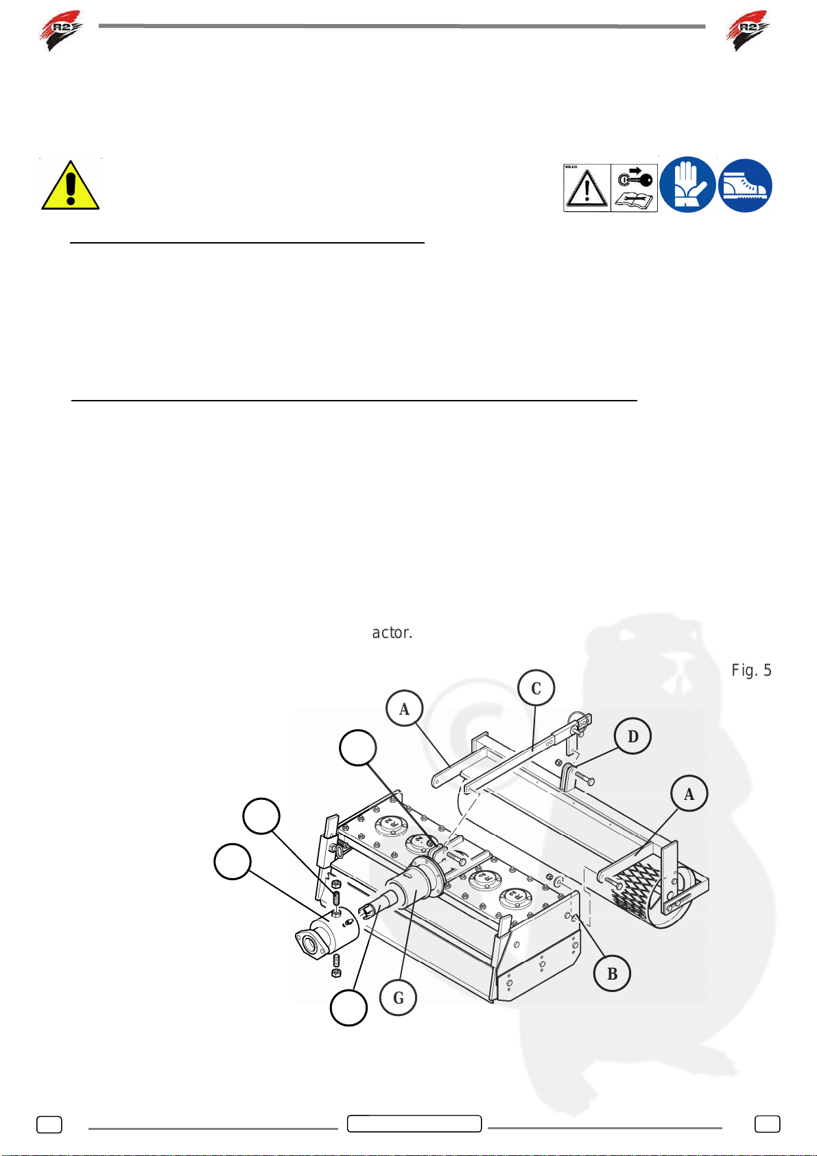
anchor points can be the roller group support and the front scraper. Make sure that the scraper
adjustment screws are properly tightened.
Always check that any walkways, ramps, etc. that must be crossed with means of conveyance and
lifting equipment are well anchored and have a capacity capable of supporting the total load of the
vehicle + machine + operator. When using ramps for loading, ensure that the vehicle has the
handbrake on and have been positioned the wedges suitable for locking the wheels.
E
A-B
D
25°
C

6
6
ENGLISH
5 – Accident prevention
(*note 4 mod. hi)
Most accidents that happen at work, during the maintenance or the shifting of a machine, are due to
negligence in the observance of the most elementary rules of accident prevention.
It is, therefore, necessary that whoever uses the machine read and respect the rules written below
and the ones on the adhesive stickers of the machine.
1. Verify that on the machine are stuck all the security signs and that they are readable.
2. Before cleaning the machine, making any adjustments or reparations, turn off the walking
tractor or tractor engine. Before each operation put the machine on the floor or on steady
supports.
3. Never approach to the machine moving parts.
4. The MILL GRADER Mod. MT – MTL – MThi - MTLhi has been manufactured for a
specialized use. It must, therefore,always be in perfect working conditions and only R2 spare
parts should be used when making any reparations.
5. Before using the machine , check the tightening of the nuts and screws, in particular those of
the hoes.
6. Keep away all the people or animals before starting to work.
7. Be careful when working alongside roads, pathways or sloping ground.
8. Do not leave the machine working without supervision.
9. While checking or repairing the machine, be sure that nobody can start it up accidentally.
10.Wear tight-fitting clothes that do not cause any footholds in the rotating parts of the machine.
11.Do not climb on the machine at work.
12.Do not interfere with objects on the machine while working.
13.Never use the machine without the back roller or without the protections delivered with the
machine. Never remove the protections.
14.In order to adjust the scraper, always turn off the walking tractor or tractor engine and make
this operation safely
15.In case the machine blocks, before making any reparations, turn off the walking tractor or
tractor engine and remove the key.
16.Always read the instruction booklet of the working equipment (walking tractor or tractor)
before fitting and using the R2 machine.Do not remove or evade the security systems of the
working equipment; before start working, be sure that the security systems of the walking
tractor or tractor work correctly; if not, do not use the machine.
17.Do not carry people , animals or objects on the machine.
18.In case of road traffic respect the regulations in force in your country; put on the machine all
the signals required.

7
7
ENGLISH
6- Components assembly and coupling of the working equipment.
(*note 5 mod. hi)
Note: all the components that make part of the machine and that must be assembled before using it,
have been designed to minimize the user’s work ; the parts should be assembled using hand tools
(wrenches).
The assembly must be made on a steady surface or on an
homogeneous level floor. During the assembly wear
leather gloves and accident-prevention shoes.
6.1 Roller group and roller adjustment rod assembly.
Put the roller group screwing the two arms (Fig. 5 – Ref. A) in the holes that you will find in the back
part of the power harrow. (Fig. 5 – Ref. B).
Screw the roller adjustment rod (Fig. 5 – Ref. C) in the points indicated on the roller support (Fig. 5 –
Ref. D ) and in the power harrow (Fig.5 – Ref. E).
NOTE: the screws used to fit the roller group and the roller adjustment rod must be well tightened in
order that all the elements can turn during the adjustment.
6.2 Flange assembly and coupling of the machine to the walking tractor or tractor.
Before fitting the machine flange (Fig. 5 - Ref. F), which varies according to the model of the walking
tractor, we advise you to apply some grease on th external diameter of the machine hub (Fig. 5 -
Ref. G) in order that the machine oscillates . Fit in the flange with two special screws (grub screws)
(Fig.5-Ref. H) and two muts; in order to fix the flange on the hub do as follows:
- Screw the grub screws completely and then turn back of one turn, close the nuts and tighten.
Once you have finished, check that the flange oscillates freely without tightening or seizing,
otherwise repeat all again.
- Put the transmission sleeve (Fig. 5 - Ref. I) on the machine shaft previously lubricated.
Afterwards, bring the walking tractor near to the machine paying attention that the sleeve
engages with the connecting-shaft of the walking tractor and that the two flanges, the one of
the walking tractor and the one of the machine, fit perfectly well; then tighten the machine
with the rods of the walking tractor or tractor.
Fig. 5
A
C
A
D
E
B
F
G
H
I

8
8
ENGLISH
7 – Preparation for use
Before using the machine it is necessary to perform the following controls with the
walking tractor or tractor off and the key off:
- Check that the lubricant is at the indicated level.
- Check the bolts tightening and that all the elements are in perfect conditions.
- Check that the signs security are present and legible.
8 – Working depth adjustment
(*note 6 mod. hi)
The working depth is adjusted by the roller support pin (Fig.6 - Ref.A); choosing a hole on the rod the
working depth can vary from 0 to 14 cm. It is important that while the operator works, lthe machine
leans on its roller.
To transport the machine applied to the walking tractor, use the first hole of the adjustment rod
(maximum extent of leverage); in this way the power harrow will not touch the soil and the roller will
function as a wheel.
In order to prevent the hoes from remaining exposed and to avoid any
dangerous situation during the milling, it is important the the extension
sides (Fig. 6 – Ref. B) are adjusted in such a way that they always touch
the soil; the extension sides adjustment must be made with the walking
tractor or the tractor off and the key off.
9 – Levelling adjustment
The levelling is made with the front shovel (Fig.6 - Ref.C); the scraper is adjusted manually with the
two special screws and depends on the working depth chosen (Fig.6 - Ref.D). For a good levelling
result, be sure that while working there is always earth in front of the scraper.
In order to prevent the hoes from remaining exposed and to avoid any dangerous
situation during the milling, it is important that the scraper is adjusted in a way that it
touches lightly the soil surface.
Adjust the scaper always with the walking tractor or tractor off and the key off.
Wear protective gloves to prevent injury to the skin of the hands.
Fig. 6
B
C
A
D

9
9
ENGLISH
10 – Machine use
(*note 7 mod. hi)
10.1 – Soil working
Once you have made the adjustments, it is possible to operate the walking tractor (or tractor) and so
the PTO that will determinate the hoes rotation . Pressing the forward, the working soil will start. The
operator’s position is at the rear of the walking-tractor (or semi-laterally where it is possible to adjust
the handlebars) or at the driver’s tractor seat.It is important to remember that while driving you
should not make any turning maneuvers (the hoes are inserted into the ground) but only small
corrections of direction.
To change direction do as follows:
1. Stop the motion of the walking tractor or tractor feed.
2. Stop the PTO motion.
3. Lift the machine using the walking tractor handlebars or the tractor lift group.
4. In order to change direction, place yourself in the track you would like to follow.
5. Lower the machine
6. Operate again the PTO motion.
7. Operate again the forward motion.
Keep in mind the rules for the prevention of accidents mentioned in Section 5.
5. Always remember to:
- Keep away people or animals from the working area; do not allow anyone to aprroach to the
machine while working.
- Never approach to the mecchanical moving parts; wear safety shoes. If while working, there is a lot
of dust (which will depend on the type of soil) wear a dust mask.
- Do not use the machine in reverse; do not use the machine on steep slopes
(verify the walking tractor or tractor instruction booklet ).
- Before operating the machine, verify that the safety system of the walking
tractor or tractor functions correctly.
10.2 – Power harrow locking
The MILL GRADER Mod. MT – MTL – MThi – MTLhi has been designed and constructed so as to
minimize the possibility that the mill grader can lock while working.
. It is not excluded, however, that this can happen if there are stones or big stones, iron wires or
other elements that can fit in or roll in the hoes. In order to avoid the power harrow from locking, we
advise to do as follows:
-Before starting to work, remove the big stones, the iron wires, etc. from the surface .
-Adjust the working depth needed.
-Replace the hoes when they are worn out (see paragraph12)
If the power harrow locks, before making any adjustment , TURN OFF
THE ENGINE of the walking tractor or tractor and REMOVE THE KEY.
The key must be kept by the person that will remove the stuff that
has locked the machine.
To unlock it, remove the stuff with a tool of lengthened shape; do not use the hands. NOTE: usually
the machine is unlocked when the walking tractor or tractor engine is turned off as there is no
pressure in the hoes that keep the blocking piece.

10
10
ENGLISH
11 - Maintenance
(*note 8 mod. hi)
Operations to be carried out in order to maintain the machine in good working conditions:
- Before using the machine:
1. Check the clamping of the walking tractor tie-rods on the machine flange.
2. Check that the screws are tight, in particular check that the hoes screws are intact, if while
working they break, it is necessary to stop working and replace them.
- At the beginning of the working season:
1. Grease the flange using the appropriate greaser (Fig. 7 Ref. A).
2. Check the grease level in the tank using the specially provided cap (Fig. 7 – Ref. B); this
must be made when the machine has worked for several minutes.
During the maintenance operations wear protective gloves; for the
lubrification/greasing operations always wear nitrile gloves and protective glasses.
If the maintenance is made on a raised plane (for example on a workbench), always wear safety
shoes.
All the maintenance work must be performed with the walking tractor or tractor off and the key off.
After finishing the lubrification/greasing operations, clean the residual of lubricant left on the floor.
Fig. 7
A
B

11
11
ENGLISH
12 – Hoes replacement
The hoes replacement must be made disassembling the roller group and placing the machine on
the back side so that the hoes are parallel to the ground. Place the machine on a stable and safe
plane. When mounting the new hoes, be sure that the clamping nut fits well in its seat (Fig. 8 Ref.
B); It is necessary to use new nuts, bolts and washers each time the hoes are replaced. N.B. Use
always original steel bolts. In order to use the hoes as much as possible, the machine has on the
sides two extensions(Fig. 6 - Ref. B), this allows to work even if the hoes are worn out, the
consumption must not exceed the 2/3 of the hoe itself.
N.B. For low-powered walking tractors (8-10HP) check that the PTO height from the ground is at
least 28-30 cms. If the height is of 25-26 cms. it is necessary to replace the hoes with shorter ones in
order that the machine is in-line with the walking tractor or tractor.
Fig. 8
While replacing the hoes, wear protective gloves. If the maintenance is made on a raised
plane, always wear safety shoes.
All the maintenance work must be made with the walking tractor or tractor off and the key off.
If the tightening of the hoes screws is
made with pneumatic screwdrivers,
put on ear protections and protective
glasses.
Tightening of the hoes screws: 85 Nm
A
C
D
E
F
A: Steel self-locking nut M10
B: Nut seat
C: Hoe fork
D: Hoe
E: Plate
F: Spring strengthened Washer
G: Steel screw M 10x1,25x45 DIN 960-8.8
B
G
10 Kg
6-7 bar

12
12
ENGLISH
13 – End of work and storage of the machine
If the MILL GRADER Mod. MT – MTL – MThi - MTLhi must remain unused for a long period, it is
necessary to perform the following steps:
1. Wash thoroughly the MILL GRADER Mod. MT – MTL – MThi - MTLhi and then dry it.
2. Check thoroughly the working of all the moving parts and replace the damaged, worn or
deteriorated ones.
3.Check the tightening of all the bolts.
4.Check the lubricant level.
5. Protect and lubricate all the metal unpainted parts, then cover the machine and keep it in a dry
place, it will be ready for use at any time.
Attention: Before using the machine again, refer to the “Maintenance” chapter.
Keep the machine in a way that people or animals do not run any risk (stumbling, machine falling
down) and protect the prominent parts in order that they do not cause injury.
To avoid danger situations, store the machine in a way that does not hamper the escape routes, the
emergency exits, fire protections (fire extinguishers, hydrants, etc.) and first aid (first aid boxes,
etc.) form the storage place.
If the washing and/or cleaning of the machine is made by compressed air
or water, be sure that there are no people or animals in the working area
and wear protective glasses and if necessary a dust mask. Do not direct
the jet of compressed air or water to people or animals.
14 – Scrapping and disposal of the components and packaging.
In case of machine scrapping it is necessary to make it unusable to prevent that others can
use it
again
; the reuse of the machine by a third party, can be dangerous and accidents can be
prosecuted according to Civil and Criminal Procedure, under the laws in force in your country
towards those that get rid of the machine without precautions.
In order to make the machine unusable, it is necessary to disassemble the pinion-hub (Fig. 5 – Ref.
G) and dispose it separately from the rest of the machine.
The machine is made of metal parts and of lubricant substances; they must be disposed in special
waste disposal centers.
According to the type of transport, the machine can be packed in a cardboard (box) wood (pallet)
plastic (polypropylene strapping and stretch film polyethylene) and metal (steel strapping seal or
wire if the machine is delivered directly on a pallet); these items must be disposed in special waste
disposal centers.
The polyethylene stretch film must not be used as a children toy because it may cause e
suffocation.
For the environment respect, dispose the materials in centers for separate collection of
rubbish.

13
13
ENGLISH
Specific references for the hydraulic machines
(*note 1 mod. hi)
The power harrows MThi and MTLhi have been
designed to be applied to hydraulic machines
which have an oil pressure between 160 and
170 bar.
1 – Register adjustment roller(screw crank)
2 - Register adjustment roller support
3 – Hydraulic motor
Fig. 9
(*note 2 mod. hi)
ModelMTL 50 hi MTL 75 hi MTL 100 hi MT 60 hi MT 90 hi
Maximum height from the ground (Fig. 5 – Ref
4) 70 cm 70 cm 70 cm 70 cm 70 cm
Oil pressure requested 150-180bar 150-180bar 150-180bar 150-180bar 150-180bar
Technical specifications of the hydaulic motor.
NOTE: the following data which concerns to the engine specifications are given by the manufacturer of the
hydaulic motor; for the specifications of the engine application to the R2 machine look at the previous table
and to the considerations of the following notes.
Data Value (Cont. Funct.)
Geometric displacement (cm³/rev.) 102
Max input pressure (bar) 210
Max operating pressure (bar) 175
Max torque (daNm) 26
Max flow (l/min) 75
Max rotating speed (rpm) 735
Max power (kw) 17
Max cont. Return pressure without drain line (bar) 0 ÷ 100 rpm 75
Max cont. Return pressure without drain line (bar) 100 ÷ 300 rpm 50
Max cont. Return pressure without drain line (bar) > 300 rpm. 25
Max return pressure with drain line (bar) 140
Max starting pressure with no load (bar) 12
Min. starting torque (daNm) at max. ∆P 21,5
1
2
3

14
14
ENGLISH
(*note 3 mod. hi)
The power harrows Mthi and MTLhi can be lifted anchoring the lifting equipment to the frame Fig. 9
Ref. 2; pay attention to the machine inclination while lifting it.
(*note 4 mod. hi)
For the hydraulic machines, it is important to consider the following rules to pevent
accidents:
- Caution: the hydraulic system is under pressure.
- Before connecting a hose to the hydraulic circuit of the tractor, be sure that the circuits side
of the tractor and side of the machine are not under pressure.
- The pipe connections are protected by rubber stoppers, to prevent foreign bodies from
entering. When the Mill Grader R2 is disconnected from the tractor , it is recommended to
place the protective taps on the pipe fittings. When the Mill Grader R2 is connected to the
tractor, the caps remain attached through a ring to the hoses, so that they can be repositioned
next time.
- Check regularly the hydraulic hoses! Ithe damaged or worn out must be replaced
immediately. The new ones must have the specifications and the quality required by the
constructor(contact our technical service).
- If there is a leak, you must repair it immediately to avoid accidents.
- All the liquids under pressure, especially the hydraulic circuit oil , can cause serious skin
accidents!In case of wounds, go immediately to the doctor: there can be risk of infection!
- Before working on the hydraulic circuit, lower
the machine, remove the pressure from the
hydraulic circuit, stop the tractor and remove
the key from the console .
- In case of repair or work wear nitrite gloves and
protective glasses.

15
15
ENGLISH
(*note 5 mod. hi)
In the hydraulic machines the register roller is a screw crank and follow the same steps as those
described in the paragraph for the rod register.
In this type of machines the tractor connection is supplied by the reseller. Address to the reseller for
the assembly connection instructions of the Mill Grader R2-Tractor. Fig. 10
Hydraulic circuit connection
A –
G1/2” main ports thread depth 15 mm
B –
G1/4” drain port thread depth 15 mm
Screw the hoses to the engine and fit them through the
quick coupling to the feed circuit and tractor drain (Fig. 11).
Note: the Mill grader R2 can work in both sense of rotation.
Always wear gloves and protective glasses.
Fig. 11
A: Main ports
B: Drain port
C: Pipe-connecting feed hose ( with sealingwasher)
D: Feed hose
E: Pipe-connecting drain hose (with sealing washer)
F: Drain hose
A
B
C
D E F
A
B

16
16
ENGLISH
(*note 6 mod. hi)
Adjust the working depth using the screw crank
(*note 7 mod. hi) (*note 8 mod. hi)
General rules for the hydraulic motor use:
- Working oil temperatures in the hydraulic system should be kept between +30°C and +60°C. The
anti-wear and lubrication properties of the oil are greatly reduced at higer temperatures.
- The ambient temperature around the engine should be between -30°C and +90°C
- Only use an oil containing antiwear additives ISO 46 or with a viscosity at normal operating
temperature of approx. 37 cSt, it should also have an adeguate viscosity index. Under no
circumsances should oil viscosity be outside the range of 22 cSt to 75 cSt.
- Before starting the hydraulic system check oil level and firm mounting of all components.
- Run the system unloaded for 10÷15 minutes to purge air from the circuit to prevent foaming and
deviation.
- Check for leak, rectify and refill reservoir
- Check oil level regularly and clean filters or replace them according to filter manufacturers advice
For maximum life from motor oil contamination shoul never exceed the 20/16 (see ISO 4406).
To ensure this level, return line filters should maintain 40 µm absolute or 25 µm nominal in open
circuit, 20 µm absolute and 10 µm nominal in closed circuit.

17
17
ENGLISH
Guarantee
Our equipment is covered by guarantee against manufacturing and/or assembly defects for 2 years
from the date of delivery to the customer.
This guarantee is limited to the replacement of defective parts and does not include labour costs or
transport.
This guarantee does not cover the following cases:
- When the user has made adaptations to the original machine.
- When the machine has been used in excess of its power limits.
- When R2 spare parts are not used.
- When the equipment is not used in accordance with the manual instructions.
- When the equipment has been used incorrectly.
The R2 Company reserves the right to modify the data in this manual whenever this is considered
necessary for technical or commercial improvements regarding the product itself.
Certification
The EC certification supplied with the
machine certifies that the machine
complies with the current provisions
of Law.
INFORMATION
The EC certificate is enclosed with
the machine documentation and
contains the manufacturer’s details,
the machine data and the machine’s
declaration of conformity according
to the Directive EC as in the copy
shown in the figure beside.
R2 Rinaldi S.r.l.
Stampato in Italia – Printed in Italy
It is forbidden to copy this booklet or part of it
without the authorization.

18
18
NOTE


R2 Rinaldi S.r.l.
Via degli Artigiani, 23
40024 – Castel San Pietro Terme
Bologna (ITALY)
Tel. (0039) 051.94.30.42
Fax (0039) 051.69.42.086
www.R2RINALDI.com
R2@R2RINALDI.com
This manual suits for next models
14
Table of contents