manuals.online logo
Brands
  1. Home
  2. •
  3. Brands
  4. •
  5. RAB Lighting
  6. •
  7. Outdoor Light
  8. •
  9. RAB Lighting WPLED26DC User manual

RAB Lighting WPLED26DC User manual

WPLED26DC INSTALLATION INSTRUCTIONS
IMPORTANT
READ CAREFULLY BEFORE INSTALLING FIXTURE. RETAIN THESE INSTRUCTIONS FOR FUTURE REFERENCE.
RAB xtures must be wired in accordance with the National Electrical Code and all applicable local codes. Proper
grounding is required for safety. THIS PRODUCT MUST BE INSTALLED IN ACCORDANCE WITH THE APPLICABLE
INSTALLATION CODE BY A PERSON FAMILIAR WITH THE CONSTRUCTION AND OPERATION OF THE PRODUCT.
WARNING: Make certain power is OFF before installing or maintaining xture. No user serviceable parts inside.
Thank you for buying
RAB LED lighting.
Comments? Call us at
888-RAB-1000, or email:
[email protected]
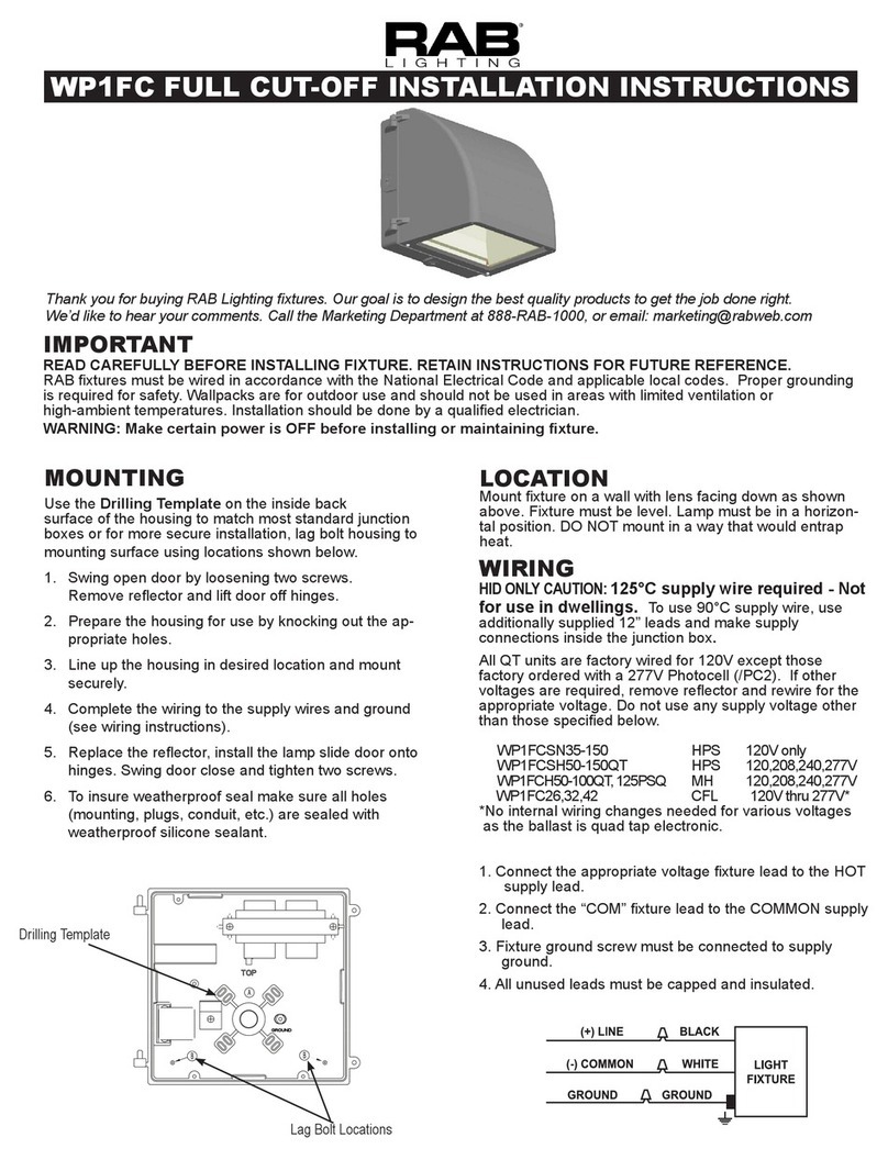
JuNcTION bOx MOuNT fOR
cONduIT
For use on applications where conduit wiring is needed.
1. Loosen and remove (4) Lens Screws. Remove Door.
2. Loosen and remove (2) Housing Screws. Remove
Housing from Back Box. Keep Housing Gasket intact
for re-assembly.
3. Secure Back Box to the mounting surface using
hardware appropriate for that mounting surface.
4. Wire the xture using UL listed wire connectors
according to NEC and local codes. Apply sealant to all
unused conduit entry points.
5. Place Gasket between Back Box and Housing.
Re-mount Housing to Back Box. Check Housing
Gasket seal all around the Back Box.
6. Re-mount Door to Housing. Tighten (4) Lens Screws.
Check door gasket (not shown) seal.
7. Fixture can be mounted in a downlight or uplight
position. Fixture may not melt heavy snow accumulation
in an uplight position.
CAUTION: For proper weatherproof function all
gaskets must be seated properly and all screws
inserted and tightened rmly.
Lens
Screws
Junction Box Surface Mount
Back Box
Housing
Gasket
Housing
Door
Housing
Screws
suRfAce MOuNT fOR Recessed
JuNcTION bOx
For use with recessed junction box and wiring.
1. Mount Surface Plate to xture with (4) Surface Plate
Screws. There are two screws from the front and two
screws from the back. Make sure Housing Gasket
makes complete seal all the way around.
2. Use supplied crossbar. Mount Crossbar to recessed
junction box with (2) screws.
3. Place Junction Box Gasket on back of the xture.
Gasket should create seal against mounting surface.
4. Wire xture to supply wires in recessed junction box
according to wiring section.
5. Use 1/4 x 20 stainless steel Mounting Screw to attach
xture to Crossbar. Tighten Mounting Screw.
6. Cover screw with Cap, provided.
7. Fixture can be mounted in a downlight or uplight
position. Fixture may not melt heavy snow accumulation
in an uplight position.
CAUTION: For proper weatherproof function all
gaskets must be seated properly and all screws
inserted and tightened rmly.
Crossbar
Junction
Box Gasket
Mounting
Screw Cap
Recessed
Junction Box
(not provided)
Surface
Plate
Housing
Gasket
(4) Surface
Plate Screws
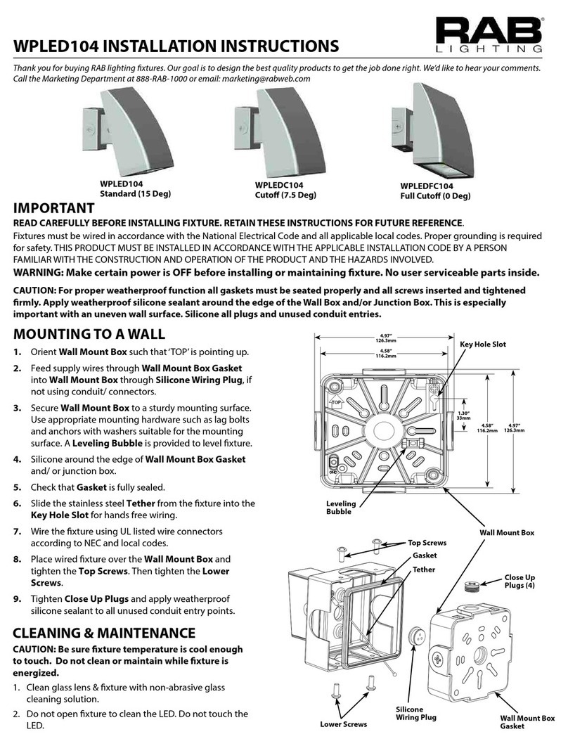
fIxTuRe MOuNTINg
To ensure weatherproof seal, apply weatherproof silicone sealant around the edge of the Housing and/or Back Box. This
is especially important with an uneven wall surface. Silicone all plugs and unused conduit entries.
WPLED26DC INSTALLATION INSTRUCTIONS
TROubLesHOOTINg
1. Check that the line voltage at xture is correct. Refer
to wiring directions.
2. Is the xture is grounded properly?
3. Is the photocell, if used, functioning properly?
WPLED26DC-IN-0213
cLeANINg & MAINTeNANce
CAUTION: Be sure xture temperature is cool
enough to touch. Do not clean or maintain while
xture is energized.
1. Clean glass lens with non-abrasive glass cleaning
solution.
2. Do not open xture to clean the LED. Do not touch
the LED.
JuNcTION bOx
1. The Junction box has (4) conduit entry points on the
center of each side and (1) in the center back.
2. Mounting Points are dimensioned below.
US and International Patents Pending
4 3/4”
2 3/16”
3 1/2”
1 1/8”
1 1/8”
Mounting Points
Note: These instructions do not cover all details or variations
in equipment nor do they provide for every possible situation
during installation, operation or maintenance.
WIRINg
Universal DC voltage driver permits operation at 10VDC
to 30VDC.
1. Connect the WHITE xture lead to the
(+) supply lead.
2. Connect the BLACK xture lead to the
(-) supply lead.
3. Connect the bare copper Ground wire from xture to
supply ground.
(+) (+) WHITE
(-) (-) BLACK
WPLED20DC INSTALLATION INSTRUCTIONS
IMPORTANT
READ CAREFULLY BEFORE INSTALLING FIXTURE. RETAIN THESE INSTRUCTIONS FOR FUTURE REFERENCE.
RAB xtures must be wired in accordance with the National Electrical Code and all applicable local codes. Proper
grounding is required for safety. THIS PRODUCT MUST BE INSTALLED IN ACCORDANCE WITH THE APPLICABLE
INSTALLATION CODE BY A PERSON FAMILIAR WITH THE CONSTRUCTION AND OPERATION OF THE PRODUCT.
WARNING: Make certain power is OFF before installing or maintaining xture. No user serviceable parts inside.
Thank you for buying
RAB LED lighting.
Comments? Call us at
888-RAB-1000, or email:
[email protected]
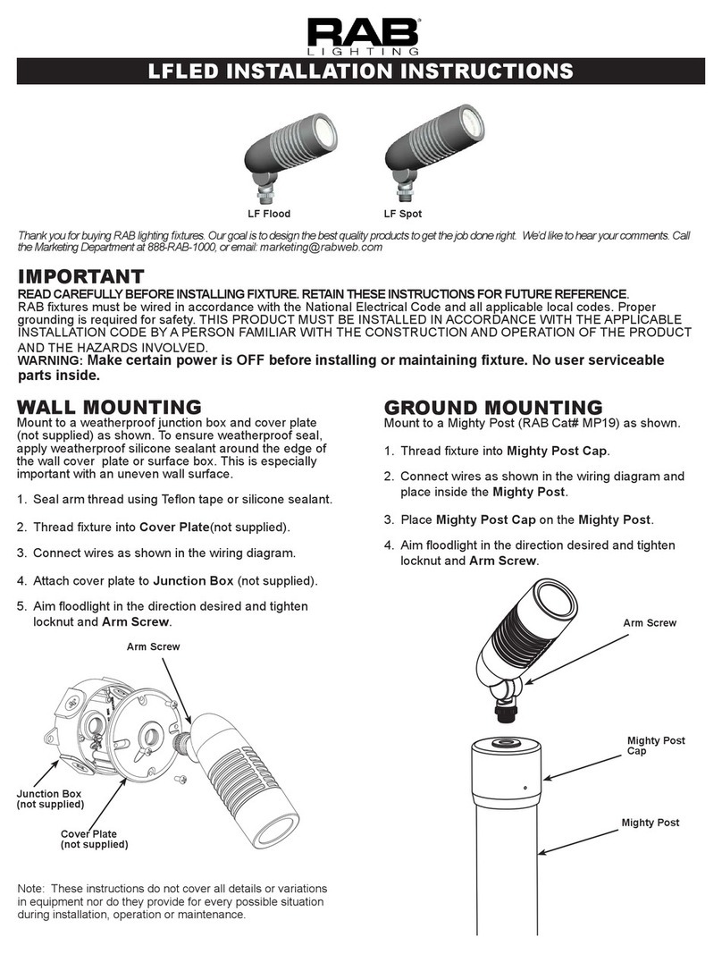
JuNcTION bOx MOuNT fOR
cONduIT
For use on applications where conduit wiring is needed.
1. Loosen and remove (4) Lens Screws. Remove Door.
2. Loosen and remove (2) Housing Screws. Remove
Housing from Back Box. Keep Housing Gasket intact
for re-assembly.
3. Secure Back Box to the mounting surface using
hardware appropriate for that mounting surface.
4. Wire the xture using UL listed wire connectors
according to NEC and local codes. Apply sealant to all
unused conduit entry points.
5. Place Gasket between Back Box and Housing.
Re-mount Housing to Back Box. Check Housing
Gasket seal all around the Back Box.
6. Re-mount Door to Housing. Tighten (4) Lens Screws.
Check door gasket (not shown) seal.
7. Fixture can be mounted in a downlight or uplight
position. Fixture may not melt heavy snow accumulation
in an uplight position.
CAUTION: For proper weatherproof function all
gaskets must be seated properly and all screws
inserted and tightened rmly.
Lens
Screws
Junction Box Surface Mount
Back Box
Housing
Gasket
Housing
Door
Housing
Screws
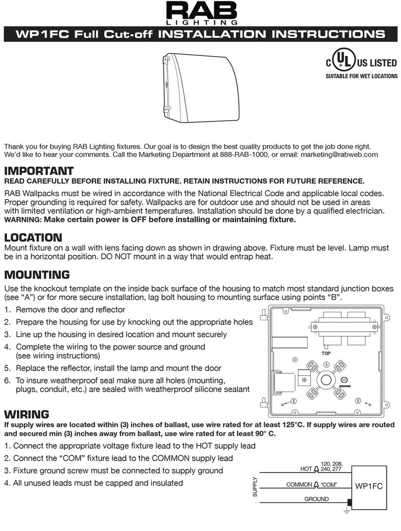
suRfAce MOuNT fOR Recessed
JuNcTION bOx
For use with recessed junction box and wiring.
1. Mount Surface Plate to xture with (4) Surface Plate
Screws. There are two screws from the front and two
screws from the back. Make sure Housing Gasket
makes complete seal all the way around.
2. Use supplied crossbar. Mount Crossbar to recessed
junction box with (2) screws.
3. Place Junction Box Gasket on back of the xture.
Gasket should create seal against mounting surface.
4. Wire xture to supply wires in recessed junction box
according to wiring section.
5. Use 1/4 x 20 stainless steel Mounting Screw to attach
xture to Crossbar. Tighten Mounting Screw.
6. Cover screw with Cap, provided.
7. Fixture can be mounted in a downlight or uplight
position. Fixture may not melt heavy snow accumulation
in an uplight position.
CAUTION: For proper weatherproof function all
gaskets must be seated properly and all screws
inserted and tightened rmly.
Crossbar
Junction
Box Gasket
Mounting
Screw Cap
Recessed
Junction Box
(not provided)
Surface
Plate
Housing
Gasket
(4) Surface
Plate Screws
fIxTuRe MOuNTINg
To ensure weatherproof seal, apply weatherproof silicone sealant around the edge of the Housing and/or Back Box. This
is especially important with an uneven wall surface. Silicone all plugs and unused conduit entries.
WPLED20DC INSTALLATION INSTRUCTIONS
TROubLesHOOTINg
1. Check that the line voltage at xture is correct. Refer
to wiring directions.
2. Is the xture is grounded properly?
WPLED20DC-IN-0213
cLeANINg & MAINTeNANce
CAUTION: Be sure xture temperature is cool
enough to touch. Do not clean or maintain while
xture is energized.
1. Clean glass lens with non-abrasive glass cleaning
solution.
2. Do not open xture to clean the LED. Do not touch
the LED.
JuNcTION bOx
1. The Junction box has (4) conduit entry points on the
center of each side and (1) in the center back.
2. Mounting Points are dimensioned below.
US and International Patents Pending
4 3/4”
2 3/16”
3 1/2”
1 1/8”
1 1/8”
Mounting Points
Note: These instructions do not cover all details or variations
in equipment nor do they provide for every possible situation
during installation, operation or maintenance.
WIRINg
Universal DC voltage driver permits operation at
10VDC to 30VDC.
1. Connect the WHITE xture lead to the
(+) supply lead.
2. Connect the BLACK xture lead to the
(-) supply lead.
3. Connect the bare copper Ground wire from xture
to supply ground.
(+) (+) WHITE
(-) (-) BLACK

Other RAB Lighting Outdoor Light manuals

RAB Lighting WP1FC FULL CUT-OFF User manual

RAB Lighting

RAB Lighting WP1FC FULL CUT-OFF User manual

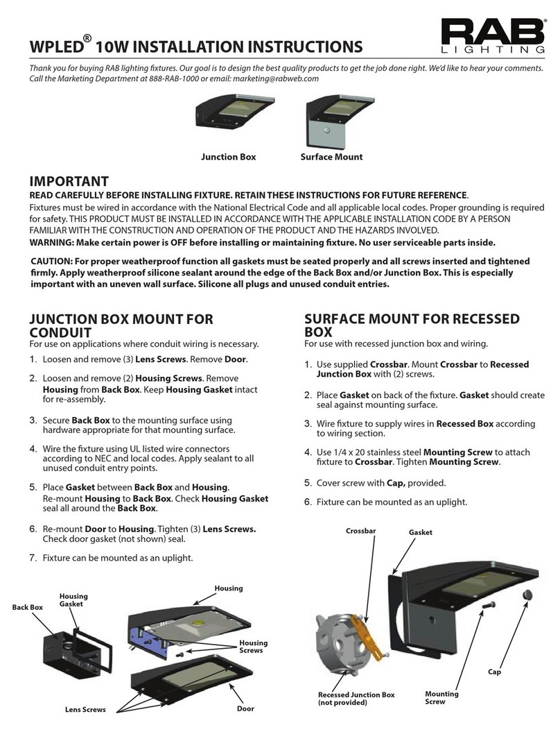
RAB Lighting WPLED 10 User manual

RAB Lighting

RAB Lighting WPLED 10 User manual

RAB Lighting WP1FC User manual

RAB Lighting

RAB Lighting WP1FC User manual

RAB Lighting WPLED52 User manual

RAB Lighting

RAB Lighting WPLED52 User manual

RAB Lighting LFLED Series User manual

RAB Lighting

RAB Lighting LFLED Series User manual

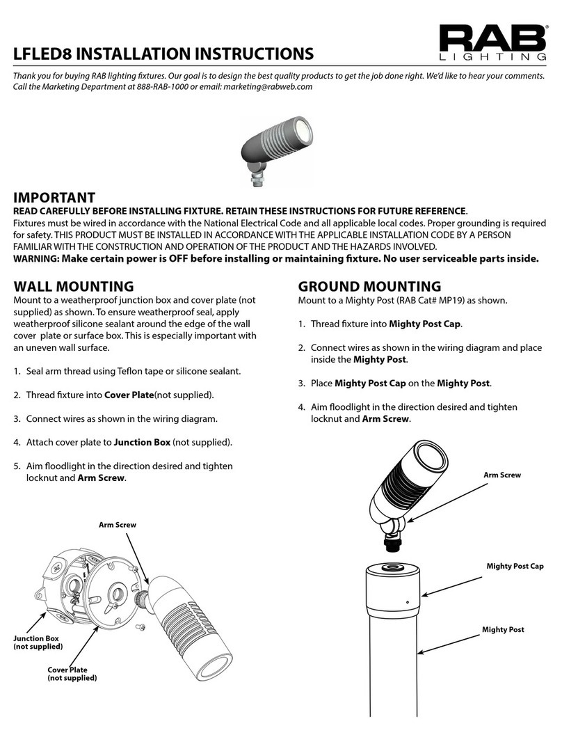
RAB Lighting LFLED8 User manual

RAB Lighting

RAB Lighting LFLED8 User manual

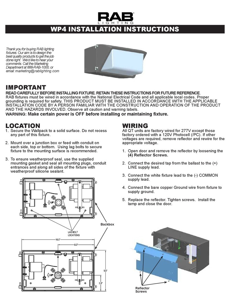
RAB Lighting WP4 Series User manual

RAB Lighting

RAB Lighting WP4 Series User manual

RAB Lighting LOTBLASTER 65W User manual

RAB Lighting

RAB Lighting LOTBLASTER 65W User manual

RAB Lighting WPLED104 Service manual

RAB Lighting

RAB Lighting WPLED104 Service manual

RAB Lighting LFLED4LV User manual

RAB Lighting

RAB Lighting LFLED4LV User manual

RAB Lighting TRIBORO TBLED Service manual

RAB Lighting

RAB Lighting TRIBORO TBLED Service manual

RAB Lighting ALED Series User manual

RAB Lighting

RAB Lighting ALED Series User manual

RAB Lighting LESLIE LES2X13 User manual

RAB Lighting

RAB Lighting LESLIE LES2X13 User manual

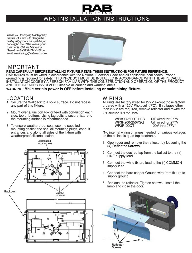
RAB Lighting WP3 User manual

RAB Lighting

RAB Lighting WP3 User manual

RAB Lighting TALLPACK User manual

RAB Lighting

RAB Lighting TALLPACK User manual

RAB Lighting HSLED Series User manual

RAB Lighting

RAB Lighting HSLED Series User manual

Popular Outdoor Light manuals by other brands

DS Produkte CF-001M/LED instructions

DS Produkte

DS Produkte CF-001M/LED instructions

Gama Sonic 16B01 instruction manual

Gama Sonic

Gama Sonic 16B01 instruction manual

LIGMAN LBX 7 installation manual

LIGMAN

LIGMAN LBX 7 installation manual

Quoizel TPE8408MB installation guide

Quoizel

Quoizel TPE8408MB installation guide

LIGMAN NORDSTROM 3 installation manual

LIGMAN

LIGMAN NORDSTROM 3 installation manual

Timberlab Basso 30 installation guide

Timberlab

Timberlab Basso 30 installation guide

LightPro Dolomite 101S Manual and safety instructions

LightPro

LightPro Dolomite 101S Manual and safety instructions

LUDECO ORSIN PL4001 manual

LUDECO

LUDECO ORSIN PL4001 manual

Trio 4035011-04 quick start guide

Trio

Trio 4035011-04 quick start guide

for Living 67064 Assembly instructions

for Living

for Living 67064 Assembly instructions

Tupex MEZZO Use and care guide

Tupex

Tupex MEZZO Use and care guide

STEINEL L 690 S manual

STEINEL

STEINEL L 690 S manual

LIGMAN POWERVISION 5 installation manual

LIGMAN

LIGMAN POWERVISION 5 installation manual

VIBIA Skan 0250 Assembly instructions

VIBIA

VIBIA Skan 0250 Assembly instructions

FUMOSA 30300 manual

FUMOSA

FUMOSA 30300 manual

LIGMAN KIOS 2 installation manual

LIGMAN

LIGMAN KIOS 2 installation manual

Livoo LH104 user manual

Livoo

Livoo LH104 user manual

Rebelle CYL-003 7600T LED Series installation instructions

Rebelle

Rebelle CYL-003 7600T LED Series installation instructions

manuals.online logo
manuals.online logoBrands
  • About & Mission
  • Contact us
  • Privacy Policy
  • Terms and Conditions

Copyright 2025 Manuals.Online. All Rights Reserved.