manuals.online logo
Brands
  1. Home
  2. •
  3. Brands
  4. •
  5. Radio Shack
  6. •
  7. Computer Hardware
  8. •
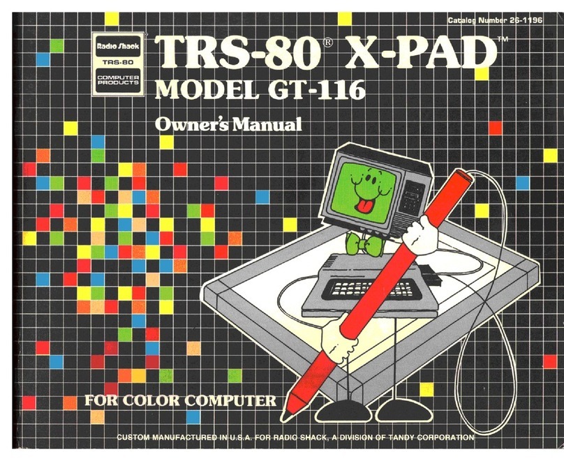
  9. Radio Shack TRS-80 X-PAD GT-116 User manual

Radio Shack TRS-80 X-PAD GT-116 User manual

Cadalocj Number 26-1196
Radio /hack
TRS-SO
caiviPUTEn
PRODUCTS
V»JA
luminal net us mi
MMiiMteWiir
IfcLi^liitLLLiiiUJI
1rJ
«
HI
IIB
«I
III
n^
*.
IB Ml I
TERMS AND CONDITIONS OF SALE AND LICENSE OF RADIO SHACK COMPUTER EQUIPMENT AND SOFTWARE PURCHASED FROM ARADIO SHACK
COMPANY-OWNED COMPUTER CENTER, RETAIL STORE OR FROM ARADIO SHACK FRANCHISEE OR DEALER AT ITS AUTHORIZED LOCATION
CUSTOMER OBLIGATIONS LIMITED WARRANTY
A. CUSTOMER assumes full responsibility that this Radio Shack computer hardware purchased (the "Equipment"), and any copies of Radio Shack software included with the
Equipment or licensed separately (the "Software") meets the specifications, capacity, capabilities, versatility, and other requirements of CUSTOMER.
B. CUSTOMER assumes full responsibility for the condition and effectiveness of the operating environment in which the Equipment and Software are to function, and for its installation.
II. RADIO SHACK LIMITED WARRANTIES AND CONDITIONS OF SALE
A. For aperiod of ninety (90) calendar days from the date of the Radio Shack sales document received upon purchase of the Equipment, RADIO SHACK warrants to the original
CUSTOMER that the Equipment and the medium upon which the Software is stored is free from manufacturing defects. THIS WARRANTY IS ONLY APPLICABLE TO PURCHASES OF
RADIO SHACK EQUIPMENT BY THE ORIGINAL CUSTOMER FROM RADIO SHACK COMPANY-OWNED COMPUTER CENTERS, RETAIL STORES AND FROM RADIO SHACK
FRANCHISEES AND DEALERS AT ITS AUTHORIZED LOCATION. The warranty is void if the Equipment's case or cabinet has been opened, or if the Equipment or Software has been
subjected to improper or abnormal use. If amanufacturing defect is discovered during the stated warranty period, the defective Equipment must be returned to aRadio Shack
Computer Center, aRadio Shack retail store, participating Radio Shack franchisee or Radio Shack dealer for repair, along with acopy of the sales document or lease agreement. The
original CUSTOMER'S sole and exclusive remedy in the event of adefect is limited to the correction of the defect by repair, replacement, or refund of the purchase price, at RADIO
SHACK'S election and sole expense. RADIO SHACK has no obligation to replace or repair expendable items.
B. RADIO SHACK makes no warranty as to the design, capability, capacity, or suitability for use of the Software, except as provided in this paragraph. Software is licensed on an "AS
IS" basis, without warranty. The original CUSTOMER'S exclusive remedy, in the event of aSoftware manufacturing defect, is its repair or replacement within thirty (30) calendar
days of the date of the Radio Shack sales document received upon license of the Software. The defective Software shall be returned to aRadio Shack Computer center, aRadio
Shack retail store, participating Radio Shack franchisee or Radio Shack dealer along with the sales document.
C. Except as provided herein no employee, agent, franchisee, dealer or other person is authorized to give any warranties of any nature on behalf of RADIO SHACK.
D. Except as provided herein, RADIO SHACK MAKES NO WARRANTIES, INCLUDING WARRANTIES OF MERCHANTABILITY OR FITNESS FOR APARTICULAR PURPOSE.
E. Some states do not allow limitations on how long an implied warranty lasts, so the above limitation(s) may not apply to CUSTOMER,
III. LIMITATION OF LIABILITY
A. EXCEPT AS PROVIDED HEREIN, RADIO SHACK SHALL HAVE NO LIABILITY OR RESPONSIBILITY TO CUSTOMER OR ANY OTHER PERSON OR ENTITY WITH RESPECT TO ANY
LIABILITY, LOSS OR DAMAGE CAUSED OR ALLEGED TO BE CAUSED DIRECTLY OR INDIRECTLY BY "EQUIPMENT" OR "SOFTWARE" SOLD, LEASED, LICENSED OR FURNISHED
BY RADIO SHACK, INCLUDING, BUT NOT LIMITED TO, ANY INTERRUPTION OF SERVICE, LOSS OF BUSINESS OR ANTICIPATORY PROFITS OR CONSEQUENTIAL DAMAGES
RESULTING FROM THE USE OR OPERATION OF THE "EQUIPMENT" OR "SOFTWARE". IN NO EVENT SHALL RADIO SHACK BE LIABLE FOR LOSS OF PROFITS, OR ANY
INDIRECT, SPECIAL, OR CONSEQUENTIAL DAMAGES ARISING OUT OF ANY BREACH OF THIS WARRANTY OR IN ANY MANNER ARISING OUT OF OR CONNECTED WITH THE
SALE, LEASE, LICENSE, USE OR ANTICIPATED USE OF THE "EQUIPMENT" OR "SOFTWARE".
NOTWITHSTANDING THE ABOVE LIMITATIONS AND WARRANTIES, RADIO SHACK'S LIABILITY HEREUNDER FOR DAMAGES INCURRED BY CUSTOMER OR OTHERS SHALL NOT
EXCEED THE AMOUNT PAID BY CUSTOMER FOR THE PARTICULAR "EQUIPMENT" OR "SOFTWARE" INVOLVED.
B. RADIO SHACK shall not be liable for any damages caused by delay in delivering or furnishing Equipment and/or Software.
C. No action arising out of any claimed breach of this Warranty or transactions under this Warranty may be brought more than two (2) years after the cause of action has accrued or
more than four (4) years after the date of the Radio Shack sales document for the Equipment or Software, whichever first occurs.
D. Some states do not allow the limitation or exclusion of incidental or consequential damages, so the above limitation(s) or exclusion(s) may not apply to CUSTOMER.
IV. RADIO SHACK SOFTWARE LICENSE
RADIO SHACK grants to CUSTOMER anon-exclusive, paid-up license to use the RADIO SHACK Software on one computer, subject to the following provisions:
A. Except as otherwise provided in this Software License, applicable copyright laws shall apply to the Software.
B. Title to the medium on which the Software is recorded (cassette and/or diskette) or stored (ROM) is transferred to CUSTOMER, but not title to the Software.
C. CUSTOMER may use Software on one host computer and access that Software through one or more terminals if the Software permits this function.
D. CUSTOMER shall not use, make, manufacture, or reproduce copies of Software except for use on one computer and as is specifically provided in this Software License. Customer is
expressly prohibited from disassembling the Software.
E. CUSTOMER is permitted to make additional copies of the Software only for backup or archival purposes or if additional copies are required in the operation of one computer with the
Software, but only to the extent the Software allows abackup copy to be made. However, for TRSDOS Software, CUSTOMER is permitted to make alimited number of additional
copies for CUSTOMER'S own use.
F. CUSTOMER may resell or distribute unmodified copies of the Software provided CUSTOMER has purchased one copy of the Software for each one sold or distributed. The
provisions of this Software License shall also be applicable to third parties receiving copies of the Software from CUSTOMER.
G. All copyright notices shall be retained on all copies of the Software.
V. APPLICABILITY OF WARRANTY
A. The terms and conditions of this Warranty are applicable as between RADIO SHACK and CUSTOMER to either a sale of the Equipment and/or Software License to CUSTOMER or to a
transaction whereby RADIO SHACK sells or conveys such Equipment to athird party for lease to CUSTOMER.
B. The limitations of liability and Warranty provisions herein shall inure to the benefit of RADIO SHACK, the author, owner and/or licensor of the Software and any manufacturer of the
Equipment sold by RADIO SHACK.
VI. STATE LAW RIGHTS
The warranties granted herein give the original CUSTOMER specific legal rights, and the original CUSTOMER may have other rights which vary from state to state.
IMPORTANT INFORMATION
This equipment generates and uses radio frequency energy. If it is
not installed and used properly, that is, in strict accordance with the
manufacturer's instructions, it may cause interference to radio
and television reception. It has been type tested and found to
comply with the limits for aClass Bcomputing device in accordance
with the specifications in Subpart Jof Part 15 of FCC Rules, which
are designed to provide reasonable protection against such inter-
ference in aresidential installation. However, there is no guarantee
that interference will not occur in aparticular installation. If this
equipment does cause interference to radio or television reception,
which can be determined by turning the equipment off and on,
the user is encouraged to try to correct the interference by one
or more of the following measures
:
•reorient the receiving antenna
•relocate the computer with respect to the receiver
•move the computer away from the receiver
•plug the computer into adifferent outlet so that computer and
receiver are on different branch circuits.
If necessary, the user should consult the dealer or an experienced
radio/television technical for additional suggestions. The user may
find the following booklet prepared by the Federal Communications
Commission helpful: How to Identify and Resolve Radio-TV
Interference Problems, This booklet is available from the United
States Government Printing Office, Washington, DC 20402, Stock
No. 004-000-0035-4.
Warning: This equipment has been certified to comply with the
limits for aClass Bcomputing device, pursuant to Subpart Jof Part
15 of FCC Rules. Only peripherals (computer input/output devices,
terminals, printers, etc.) that are certified to comply with the Class
Blimits may be attached to this computer. Operation with non-
certified peripherals is likely to result in interference to radio and
TV reception.
SERVICE POLICY
Radio Shack's nationwide network of service facilities provides
quick, convenient, and reliable repair services for all of its computer
products, in most instances. Warranty service will be performed in
accordance with Radio Shack's Limited Warranty. Non-warranty
service will be provided at reasonable parts and labor costs.
Because of the sensitivity of computer equipment, and the problems
which can result from improper servicing, the following limitations
also apply to the services offered by Radio Shack;
1. If any of the warranty seals on any Radio Shack computer
products are broken, Radio Shack reserves the right to service
the equipment or to void any remaining warranty on the equip-
ment.
2. If any Radio Shack computer equipment has been modified
so that it is not within manufacturer's specifications, including,
but not limited to, the installation of any non-Radio Shack parts,
components, or replacement boards, then Radio Shack reserves
the right to refuse to service the equipment, void any remaining
warranty, remove and replace any non-Radio Shack part found
in the equipment, and perform whatever modifications are
necessary to return the equipment to original factory manufac-
turer's specifications.
3. The cost for the labor and parts required to return the Radio
Shack computer equipment to original manufacturer's specifica-
tions will be charged to the customer in addition to the normal
repair charge.
To Our Customers ..
.
The TRS-80® X-Pad (Model GT-116) is arevolutionary
way to take advantage of the high-resolution graphic
capabilities of your TRS-80 Color Computer.
With aminimum of programming, the X-Pad lets you plot
graphics that are displayed on your Color Computer's TV
Screen. Furthermore, all graphic displays can be saved on
cassette tape for later use or printed on agraphics printer
for "hard-copy" output.
The X-Pad will open an entire world of graphic
applications for you —mapping, graphic displays,
statistics, waveform analysis, marketing analysis, and
charting, to name just afew. Besides that, it's fun!
To use X-Pad, you'll need a:
•16K or 32K Color Computer with Extended Color
BASIC.
•Color TV.
And while not required, it is extremely convenient to save
your programs on cassette; we suggest the CTR-80A
Cassette Recorder (Radio Shack Catalog Number
26-1206).
About This Manual ..
.
In this manual, we'll be showing you how to program and
use your X-Pad.
We're going to follow this course:
•First we'll be describing how to connect the X-Pad.
•Then we'll let you try afew short programs.
•Next we'll discuss the X-Pad, its parts and its
functions, in detail.
•We'll also show you afew programs you can use.
You might find it convenient to review the Extended
Color BASIC manual (Going Ahead With Extended Color
BASIC) before using the X-Pad.
TRS-80® X-Pad Owner's Manual
©1982 Tandy Corporation
All Rights Reserved
Reproduction or use, without express written permission
from Tandy Corporation, of any portion of this manual is
prohibited. While reasonable efforts have been taken in
the preparation of this manual to assure its accuracy,
Tandy Corporation assumes no liability resulting from
any errors or omissions in this manual, or from the use of
the information obtained herein.
CONTENTS
Introduction 1
1/ Getting Started 3
2/ Meet Your X-Pad (Line, Box, Point) 5
3/ The X-Pad's Surface Area 9
4/ It's aBird, It's aPlane, No It's ...X-Pad! 15
5/ Art For X-Pad's Sake (Drawing) 17
6/ From Here to Eternity (Length) 19
II Plenty of Air and Plenty of Room (Area) 21
8/ Circling the Landing X-Pad (Circles) 23
9/ Brushing on the First Coat (Painting) 25
10/ Menu or Ala Carte? (Menu) 31
11/ ADisplay Saved .. . (CSAVEM/CLOADM) 35
12/ Troubleshooting and Maintenance 39
Appendix A/ Specifications 41
Appendix B/ Pen Status Summary 43
Appendix C/ Chapter Checkpoint Answers 45
Appendix D/ X-Pad Data Interpretation 47
Appendix E/ Template/Menu Demonstration Program 49
Appendix F/ Defining Your Own Menu Commands 55
Important Note!
Be sure your Color Computer is turned OFF before you
insert or remove the X-Pad's Interface Pak; otherwise,
damage to the Color Computer or X-Pad (or both) may
occur.
Introduction
The TRS-80 X-Pad is basically an X-Y coordinate
digitizer that converts aposition on the X-Pad into an
equivalent position on the TV Screen of the Color
Computer-
After coordinates are digitized by the X-Pad and sent to
the Color Computer, the Computer reads the data (e.g.,
the X-Y coordinates) and interprets that information
according to the program you're currently running.
Sometimes you might use the X-Pad to calculate the
distance between two points or compute the area of a
geometric figure. Other times, your program might allow
you to draw lines, boxes, circles, or any other graphic
display you can imagine.
In other words, the same graphic figures you're drawing
on the X-Pad appear on the Color Computer's TV Screen
—but in full color. As you can imagine, the graphic
possibilities are nearly endless!
It's important to remember, however, that the X-Pad does
not do this "automatically". The action of the X-Pad
depends upon the program you're running with the Color
Computer.
In this manual, we've included many sample programs
you can use, but we're also going to show you how to write
your own programs (and we hope you will!).
1/ Getting Started . .
.
Before setting up the X-Pad, you'll need to connect your
Color Computer to the TV. See your TRS~80mColor
Computer Operation Manual for details. Do not turn the
Computer's power ON!
Figure 1. X-Pad
The X-Pad consists of three parts. These are the:
•Pen which enables communication between the X-Pad
and the Computer,
•Pad which is the base of the GT-116 and which has an
8-1/2" x11" Writing Surface. Do not write on the Pad!
Always be sure to have asheet of paper covering the
Pad's surface.
•X-Pad Interface Pak which is inserted into the
cartridge slot on the right side of the Color Computer.
Setting Up the X-Pad
Each time you use the X-Pad, you should put asheet of
standard-sized 8-1/2" xIT' paper over the Writing Surface
of the Pad,
Paper on the Wtiting Surface protects the surface and
keeps it clean mwell.
Connecting the X-Pad
You must connect the X-Pad to the Color Computer before
turning the Computer ON!
1. Be sure the Writing Surface is clean and dry.
2. Place asheet of standard-sized paper (8 1/2" x11") on
the Writing Surface. You can tape the paper in place (a
piece of tape at each of the Pad's corners will do the
trick).
3. Turn the TVON, select channel 3or 4, and set the
Antenna Switch to COMPUTER.
4. Carefully insert the Interface Pak into the cartridge
slot (on the right side of the Computer). Be sure the
Pak is firmly connected to the Computer.
5. Turn the Computer ON.
6. The Extended Color BASIC start-up message, followed
by OK fwill appear on the TV.
The Computer and the X-Pad are now ready for use.
Using th« Pen
When the Pen kon the Writing Surface (or even near!)
and you move tlie tip of the Pen around, asignal which
defines an X-Y coordinate is "sent" to the Computer.
What the Computer does with that signal depends on the
program you're running.
Some programs will require that you actually have to
press the tip of the Pen down on the paper; other
programs simply require that you move the Pen from one
position to another.
Important Note! Do not use apencil or felt-tip pen to
write on paper that is on the X-Pad surface or inaccuracy
may occur.
For consistent repeatibility of data, you must maintain a
consistent angle when holding the Pen.
Chapter 1Checkpoint
1. The X-Pad works by:
a. reading points with light.
b. ultrasound.
c. digitizing coordinates.
d. biorhythms.
2. The X-Pad has three parts:
a. Pen, Interface Pak, and Keyboard.
b. Pen, Interface Pak, and Pad.
c. Pen, Keyboard, and Tape Recorder.
2/ Meet your X-Pad
So What's the Point?
The point is —X-Pad is easy and fun to use!
The following Extended Color BASIC program sets
individual points on the Color Computer TVScreen.
Before you type in the program:
Be sure your X-Pad isproperly connected.
[<£] Insert asheet ofpaper on the Writing Surface.
fij Take aruler, place it horizontally near the center ofthe
paper, and draw a4" horizontal line
.
Nowtype in this program:
10 PMODE Htl :REM POINT PROGRAM
20 PCL5
30 SCMEN 1*1
40 GOSUB 80
50 IF S< >3 THEN fl0
G0 PSET(X *Y »i
)
70 GOTO 40
80 X=PEEK(E537G) :Y=PEEK (S5377 )
:
S=PEEK fB537B) jRE TURN
and RUN it.
Take the Pen and position the tip over the left end of the
line you drew. Press down on the Pen (a light touch is all
that's needed}. Notice that adot (point) appears on the
Screen.
Next position the Pen's tip over the right end of the line
and press down lightly. Note that another dot appears on
the Screen.
To create more dots, simply move the Pen to other points
on the paper and press the Pen down.
You can set as many points as you want by just running
the program once. To clear the Screen, press (BREAK) and
re-run the program.
Let the Pixels Fall
Where They May ..
.
As areview of the Color Computer Extended BASIC
language, this is what happens in the program:
•Line 10 (PMODE 4,1) creates the point size
("resolution") and specifies atwo-color "high
resolution".
•Line 20 (PCLS) clears the Graphics Screen.
•Line 30 (SCREEN 1,1) selects the Graphics Screen and
the Color Set (black and green).
•Line 40 (GOSUB 80) tells the Computer to
automatically branch to the subroutine in line 80.
•Line 50 (IF S<>3 THEN 40) decides that, if S(which
represents the Pen) is not touching the X-Pad's surface,
program control goes to line 40, Since S=3when the
Pen is on the X-Pad, program control goes to the next
program line.
•Line 60 (PSET(X,Y,1)) sets the X-Y coordinates and
specifies the points' color.
•Line 70 (GOTO 40) sends the Computer to line 40 so
you can set more points.
•Line 80 (X-PEEK(65376):Y =PEEK(65377):S =PEEK
(65378) :RETURN) accesses each memory location in the
X-Pad where digitized data is available. You'll have to
include these PEEK statements in each X-Pad program
you write.
The Big Cheese —PEEK
After running the program, it should be obvious to you
that there aren't any new commands the X-Pad uses.
The only special thing the X-Pad does is to PEEK into
certain memory addresses which store information about
the current X-Y coordinates of the Pen (see line 80).
You'll have to PEEK into these memory locations in every
X-Pad program you write.
Do you want to see what we mean? If so, type in this
program:
NEW (ENTEffi
10 PRINT PEEK<G537S>
5
20 PRINT PEEK(65377)
5
30 PRINT PEEK(65378)
40 A$=INKEY$: IF A$="
50 GOTO 10 THEN 40
Position the Pen above the Writing Surface of the X-Pad
and RUN the program. The Screen will display arow of
three numbers. For now, all you want to concentrate on is
the first two (but don't totally ignore the number on the
right. We'll ccme back to it later). Move the Pen to a
different position and press any key on the Keyboard.
Three more numbers should appear. Repeat the operation
as much as you like.
Are you ready for some answers? The first column of
numbers (i.e., on the left side of the Screen) contains the
X-coordinate value for the current Pen position. Memory
location 65376 contains that information.
The second column is the current Y-coordinate value.
Memory location 65377 contains that information.
(And the third number is the current Pen Status —but
more on that later!)
As you move the Pen from location to location (i.e.,
"location" defined by an X-Y coordinate value), the X-Y
coordinate values change.
•Line 10 of the program continuously returns the
current X-coordinate of the Pen. This number will
always be between and 255. (Unless you move the
Pen into a"margin" where the counting wraps-around.)
•Line 20 continuously returns the current
Y-coordinate of the Pen. This number will always be
between 0-191. (Unless you move the Pen into a
"margin" where the counting wraps-around.)
(And line 30 returns the current Pen Status.)
6
Color Computer/ X- Pad Memory Locations
Address Function
65376 Reads the current X-Axis Coordinate on
the horizontal axis.
65377 Reads the current Y-Axis Coordinate on
the vertical axis.
65378 Reads the current Pen Status.
Table 1
For example, if the Pen is postioned at an X-coordinate
reading of 228 and aY-coordinate of 120 with aPen
Status of 3, the data might be displayed this way:
18 120
And that's really all there is to the X-Pad! Of course,
what you do with those X-Y values (and the Pen Status)
is where all the fun comes in,
Everything Points In
that Direction
Now run the Dot program again, but first change line 10
to:
10 PMQDE 2>1
Create some dots. Notice that this time the dots are larger
since you're using "lower resolution".
Change line 30 to:
30 SCREEN 1,0
and RUN the program. SCREEN 1,0 changes the Screen
to the two-color low resolution mode of black and green.
Gotta Draw the Line Somewhere
In Color Computer graphics, every line you draw has a
^startpoint" and an "endpoint"
startpoint endpoint
Figure 2. Line
This next program draws aline on the Screen after you
simply specify astartpoint and an endpoint on the X-Pad
(with the Pen).
Place the sheet of paper with the 4" line on the X-Pad and
type this program:
5REM LINE PROGRAM
10 PMODE 4,1
20 PCLS
30 SCREEN 1,1
40 GDSUB 140
50 IF S<>3 THEN 40
B0 PSET(XtY»l)
70 IF PEEK(S537S)-3
80 X1=X:Y1~Y
90 GDSUB 140
100 IF S<>3 THEN 90
110 LINE(X1 tYl)-<X *Y)
120 IF PEEK(G537B)=3
130 GOTO 40
140 X=PEEK(G5376) :Y=PEEK <65377
)
:S= PEEK (65378) RETURN
RUN the program. Now position the Pen to the left end of
the line and press down. Then move it to the right end of
the line and press down again, Aline will appear on the
Screen.
THEN 70
>PSET
THEN 120
Go ahead —take the Pen by the horns! Specify several
points on X-Pad and draw several lines. Now try drawing
lines using varying lengths (8", 10", 5", etc.). Be sure to
experiment with horizontal, vertical, and diagonal lines.
You might also try changing PMODEs (for lower
resolution and thicker lines) and SCREEN (for different
Color Sets).
What happens is this:
•Line 40 goes to 140 and gets the data.
•Line 50 waits for Pen down.
•Line 60 gets the first point.
•Line 70 waits for Pen up.
•Line 80 saves the first point.
•Line 90 gets the data.
•Line 100 draws the line.
•Line 110 draws the line.
•Line 120 waits for Pen up.
•Line 130 goes back for more data.
To draw atriangle, box, or rectangle, specify astartpoint
and endpoint for the first side of the figure. Then use that
endpoint as the next startpoint. Repeat this procedure for
all the sides of the figure.
Notes
Chapter 2Checkpoint
1. (True/False) PEEK addresses X-Pad's memory
locations.
2. Before you enter aprogram:
a. be sure X-Pad is properly connected.
b. insert asheet of paper on the Writing Surface.
c. be sure the Color Computer is powered-up.
d. all of the above.
e. none of the above.
3. Aline has:
a. two endpoints.
b. astartpoint and an endpoint.
c. alinear row of points.
d. all of the above.
e. none of the above.
3/ The X-Pad's Surface Area
You should know that there are two areas on the Writing
Surface of the Pad. They are the:
•Display Area. This area takes up most of the Writing
Surface of the Pad. Anytime you move the Pen into this
area, adisplay will appear on the Screen.
•Menu Area. This area makes up the "margins" of the
Pad, Anytime the Pen moves into this area, the Screen
doesn't display anything but something does happen.
Well go into this in more detail later in this section.
-Display Area
Menu Area
Figure 3. X-Pad Writing Surface
Note that the X-Pad's Display Area is the same size as
the Display Area of the Color Computer.
9
Figure 4. X-Pad Display Area vs. Screen Display Area
Anytime the Pen moves onto the X-Pad's Display Area
(see Figure 6later in this manual, as well), agraphics
display will appear on the Screen. (You can also use this
area to create amenu, but it is primarily designed for
display only!)
The Menu Area, which is the margin area and which runs
around the perimeter of the Display Area (about 1" from
the edge all around), works differently. The X-Pad will
send signals from that area but will not display anything
on the Screen, Nevertheless, this Area is extremely
powerful. For instance, you might assign various
Extended Color BASIC commands to sections in the Menu
Area. Then, instead of typing in acommand (such as
PAINT) from the Keyboard, just touch with the Pen that
part of Menu assigned to PAINT and that statement will
be the next one used.
You can think of the Display Area of the X-Pad as having
an imaginary Cartesian coordinate (point-plotting)
system. The range for Xis to 255 and the range for Yis
to 191. The upper-left corner is the origin (0,0), the
upper-right corner is (255,0), the lower-left corner is
(0,191) and the lower-right corner is (255,191), The
centerpoint is (127,95),
On the Writing Surface, Xand Yare measured by the
X-Pad in "increments" or individual units of calibration.
Each of these increments represents one pixel on the
Color Computer's Graphic Screen.
Marginally Speaking ..
.
In the Menu Area, there are three types of margins on the
Writing Surface of the X-Pad:
•X-Margin, the left and right vertical margins.
•Y-Margin, the top horizontal margin.
•Bottom Margin, the bottom horizontal margin but can
be defined by your program.
(0,0) (255,0)
V+y
(0,191) (255,1911
10,200) 1255,2001
Figure 5. X-PacTs Margins and Cartesian System
The Cartesian System
According to X-Pad
We've already talked about the X-Pad Cartesian system.
Bat since you now know about X-Y coordinates, here are
some more important facts about X-Pad's plotting system:
•The center of the Cartesian system is (127,95).
•If you move the Pen beyond the range (into amargin,
10
for instance), the counting "wraps-around" or starts
over.
•The range for Yis to 191, but you will get greater
values for Ybecause coordinate counting wrap-arounds
at the Top margin.
To see how this coordinate wrapping works, try this
(Note: The coordinates listed below are approximate.
Your actual readings will be near these.):
1. Enter the one-line PEEK program and RUN it:
10 PRINT PEEKCS537S) 5PEEK (G5377 >5
PEEK(G5378) :G0T0 10
2. Take the Pen and put it down as far to the left of the
left margin as you can. Your Screen should display
about 240.
3. Now move it horizontally from this point to the
furthest point to the right of the right margin. As you
move from left to right, the horizontal Xcoordinate
(the only one we're changing since we're moving
horizontally) is about 240; then it goes to 255 (end of
margin), to (start of the Display Area), to 255 (end of
Display Area), to 0, and then begins counting to about
15.
(Pen) Status Conscious
Remember earlier we talked about Pen Status (i.e., the
third column of numbers on the Screen)?
Pen Status tells the Computer the current location and
condition of the Pen. There are 16 different statuses: 0-15.
Pen Status 3("Pen pressed down on Display Area") is the
normal operating condition.
Why do you need to worry
about Pen Status?
Simple. Programs that you write for the X-Pad will
usually incorporate information about Pen Status.
The Pen Status information provides additional
capabilities in the use of the X-Pad. Pen Proximity
provides ameans of disabling data when the Pen is out of
range of the Writing Surface. Pen Down tells the
Computer when the Pen is touching the Writing Surface.
Xand Ymargins tell when the Pen is beyond the 7" x9"
Display Area and defines left, top and right margin areas
that can be used for menu or other purposes. Alower
margin is not defined. However, alower margin can be
easily created in your program. It should be noted that a
menu can be created in the Display Area as well as the
Menu Area.
For instance, in the sample programs we've shown you so
far, Shas been used as avariable representing the Pen's
Current Status (S =PEEK(65378)) and we've also tested
that current status with an IF/THEN statement (IF S=3
THEN 40, for instance). What this IF/THEN statement is
really saying is, "If the Current Pen Status is Ten
pressed down on the Display Area', then goto line 40". In
all other instances (such as if the Pen were pressed down
on the Menu Area), the program would continue
execution at the next line.
Other examples include:
100 IF S<>3 THEN 90
This program line waits until you press the Pen down on
the Display Area or on the bottom margin.
220 IF S=15 THEN RETURN
This program line reads if the Pen is pressed down in the
upper-left or upper-right corner of the margins.
There are several Pen Statuses (4-15) that tell you when
you are beyond the perimeters of the 7" x9" Display Area.
Three of the Statuses (5, 9, and 13) rarely occur and are
difficult to reproduce. However, since these are possible,
they are included in the list.
11
X-Pad Pen Status
Signal Sent to
Computer Meaning
4
1
2
5
6
8
g
10
12
13
14
15
Pen not down, out of range of Pad
(Pen out of proximity)
Pen down, oft Pad
Pen near Surface {within 1")
(Pen proximity only)
Pen down on Display Area or on bottom
margin
(Pen down and proximity)
Pen not within 1" of X-margin (left or
right margin)
X-margin and Pen down
Pen touching paper on X-margin (left or
right margin) but Pen not down
(X-margin and proximity)
Pen down on X-margin (left or right
margin) (X-margin, Pen down, and
proximity)
Pen not within 1"of the Y-margin (top
margin)
Y-margin and Pen down
Pen within 1" of Y-margin (top
margin) (Y-margin and proximity)
Pen down on Y-margin (top margin)
(Y-marginTPen down, and proximity)
X- and Y-margin
X- and Y-margin and Pen down
Pen touching paper in upper-right or
upper-left X-Y corner but Pen not down
(X- and Y-margin and proximity)
Pen down in upper-right or upper-left
X-Y corner (X- and Y-margin, Pen down,
and proximity)
Table 2
Status 1might be confusing ("Pen down, off Pad"). This
Status means the tip of the Pen is being held down but
the Pen is not on the Pad.
Type this one line program and RUN it:
10 PRINT PEEK(G537SJ :G0T0 10
The program, which PEEKs the memory address for Pen
Status, displays the current Pen Status on the far left side
of your Screen.
With the program running:
1. Hold the Pen vertically about 4" above the center of the
Display Area (with the point of the Pen down). APen
Status of ("Pen not ready, out of range of Pad") will
be in effect.
2. Slowly move the Pen downward towards the Display
Area. When you are about 1" from the Surface, the
Status changes to 2CPen near Display Area"),
3. Move the Pen onto the Surface and apply slight
pressure. The Pen Status changes to 3("Pen down on
Display Area or on Bottom Margin").
To show you the Pen Status of the margins, keep the
same one-line program (10 PR INT
PEEKC65378) :G0T0 10) *
1. Press the Pen down on the center of X-Pad (reading: 3,
"Pen down on Display Area or on Bottom Margin").
2. From the center, move the Pen diagonally to the lower
right corner (reading: 7, "Pen down on Xmargin") and
press down,
3. Then move the Pen vertically up the right margin
(reading: 7) to the upper right corner (reading: 15t
"Pen down in upper right or upper left X-Y corner").
Press down.
4. Move the Pen across the top margin (reading: 11, "Pen
down on Ymargin") to the upper left corner (reading:
15) and press down.
5. Then move the Pen down the left margin (reading; 7)
to the lower left corner (reading: 7). Press down.
6. Move the Pen across the bottom margin (reading: 3) to
the lower right corner (reading: 7).
12
Chapter 3Checkpoint Notes
1. Name the two areas on the surface of X-Pad.
2. X-Pad can read coordinates when the Pen is:
a. on the Writing Surface.
b. on the Active Surface.
c. anywhere on the Pad.
d. all of the above.
3. The origin coordinate on X-Pad is located in the:
a. upper-left corner.
b. lower-left corner.
c. upper-right corner.
d. lower-right corner.
e. none of the above.
4. (True/False) You set the Working Area using PMODE
in your program.
5. The coordinate (255,0) is located in the:
a. lower-left corner.
b. upper-right corner.
c. upper-left corner.
d. lower-right corner.
e. none of the above.
13

Other manuals for TRS-80 X-PAD GT-116

1

Other Radio Shack Computer Hardware manuals

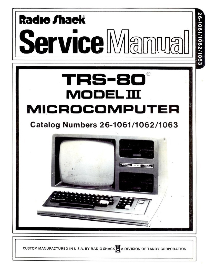
Radio Shack TRS-80 User manual

Radio Shack

Radio Shack TRS-80 User manual

Radio Shack TRS-80 X-PAD GT-116 User manual

Radio Shack

Radio Shack TRS-80 X-PAD GT-116 User manual

Radio Shack Deluxe RS-232 User manual

Radio Shack

Radio Shack Deluxe RS-232 User manual

Radio Shack TRS-80 User manual

Radio Shack

Radio Shack TRS-80 User manual

Radio Shack 26-3801 User manual

Radio Shack

Radio Shack 26-3801 User manual

Radio Shack VoxBox TRS-80 User manual

Radio Shack

Radio Shack VoxBox TRS-80 User manual

Radio Shack Bluespoon 17-1000 User manual

Radio Shack

Radio Shack Bluespoon 17-1000 User manual

Radio Shack Telephone Interface II User manual

Radio Shack

Radio Shack Telephone Interface II User manual

Popular Computer Hardware manuals by other brands

Sensata Magnum Energy MSH Series quick start guide

Sensata

Sensata Magnum Energy MSH Series quick start guide

Linear Technology LTC2923 quick start guide

Linear Technology

Linear Technology LTC2923 quick start guide

Cirrus Logic ARM CDB89712 user manual

Cirrus Logic

Cirrus Logic ARM CDB89712 user manual

Zmotion ZMIO300 Series Hardware manual

Zmotion

Zmotion ZMIO300 Series Hardware manual

Panasonic AJHDP2000 - 2K PROCESSOR operating instructions

Panasonic

Panasonic AJHDP2000 - 2K PROCESSOR operating instructions

Alphacool Eisbecher All in One 250 mm instruction manual

Alphacool

Alphacool Eisbecher All in One 250 mm instruction manual

Phanteks GLACIER G3090Ti MSI installation guide

Phanteks

Phanteks GLACIER G3090Ti MSI installation guide

Cypress Semiconductor AutoStore STK14CA8 Specification sheet

Cypress Semiconductor

Cypress Semiconductor AutoStore STK14CA8 Specification sheet

ekwb EK-FB KIT ASUS R4BE Installation and mounting manuals

ekwb

ekwb EK-FB KIT ASUS R4BE Installation and mounting manuals

Renesas Single-Chip Microcomputer M34519T-MCU user manual

Renesas

Renesas Single-Chip Microcomputer M34519T-MCU user manual

Yamaha MY8-SDI-ED owner's manual

Yamaha

Yamaha MY8-SDI-ED owner's manual

VIA Technologies AMOS-820 SKU Development guide

VIA Technologies

VIA Technologies AMOS-820 SKU Development guide

Intel CD1IV128MK manual

Intel

Intel CD1IV128MK manual

Adaptec 2100S - SCSI RAID Controller quick start guide

Adaptec

Adaptec 2100S - SCSI RAID Controller quick start guide

Arduino MKR IoT Carrier Rev2 Product reference manual

Arduino

Arduino MKR IoT Carrier Rev2 Product reference manual

DFI HR902-B/BL Series user manual

DFI

DFI HR902-B/BL Series user manual

OLIMEX ESP32-C6-EVB user manual

OLIMEX

OLIMEX ESP32-C6-EVB user manual

Ikegami IK-VS4 operating instructions

Ikegami

Ikegami IK-VS4 operating instructions

manuals.online logo
manuals.online logoBrands
  • About & Mission
  • Contact us
  • Privacy Policy
  • Terms and Conditions

Copyright 2025 Manuals.Online. All Rights Reserved.