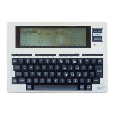
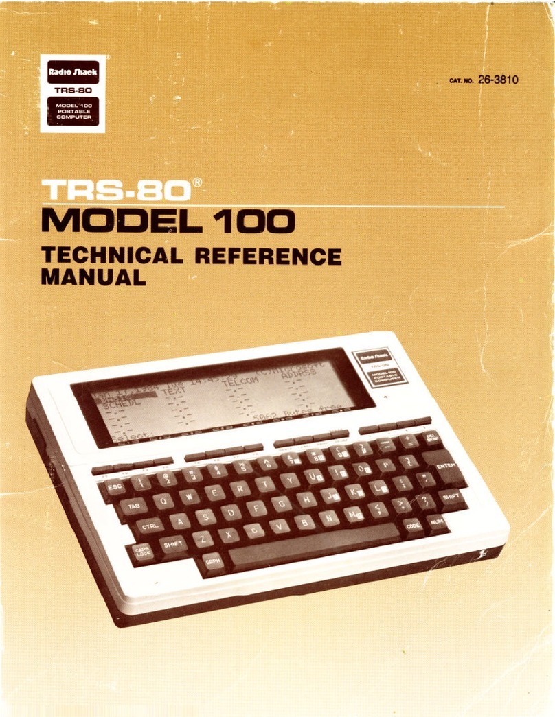
Radio Shack Tandy 200 Product manual

Tandy 200 Technical Reference Manual
26-3861


TERMS AND CONDITIONS OF SALE AND LICENSE OF TANDY COMPUTER EQUIPMENT AND
SOFTWARE PURCHASED FROM RADIO SHACK COMPANY-OWNED COMPUTER CENTERS, RETAIL
STORES AND RADIO SHACK FRANCHISEES OR DEALERS AT THEIR AUTHORIZED LOCATIONS
LIMITED WARRANTY
I. CUSTOMER OBLIGATIONS „,„ j
A. CUSTOMER assumes full responsibility that this computer hardware purchased (the "Equipment' ), and any
copies of software included with the Equipment or licensed separately (the "Software") meets the specifications,
capacity, capabilities, versatility, and other requirements of CUSTOMER.
B. CUSTOMER assumes full responsibility for the condition and effectiveness of the operating environment in which
the Equipment and Software are to function, and for its installation.
II. LIMITED WARRANTIES AND CONDITIONS OF SALE
A. For aperiod of ninety (90) calendar days from the date of the Radio Shack sales document received upon
purchase of the Equipment. RADIO SHACK warrants to the original CUSTOMER that the Equipment and the
medium upon which the Software is stored is free from manufacturing defects. This warranty It only applicable
to purchases ol Tandy Equipment by tha original customer from Radio Shack company-owned computer
centers, retail stores, and Radio Shack franchisees and dealers at their authorized locations The warranty is
void if the Equipment's case or cabinet has been opened, or if the Equipment or Software has been subjected to
improper or abnormal use. If amanufacturing defect is discovered dunng the stated warranty period, the defective
Equipment must be returned to aRadio Shack Computer Center, aRadio Shack retail store, aparticipating Radio
Shack franchisee or aparticipating Radio Shack dealer for repair, along with a copy of the sales document or
lease agreement. The original CUSTOMER'S sole and exclusive remedy in the event of adefect is limited to the
correction of the defect by repair, replacement, or refund of the purchase price, at RADIO SHACK'S election and
sole expense. RADIO SHACK has no obligation to replace or repair expendable items.
B. RADIO SHACK makes no warranty as to the design, capability, capacity, or suitability for use of the Software,
except as provided in this paragraph. Software is licensed on an AS IS" basis, without warranty. The original
CUSTOMER'S exclusive remedy, in the event of aSoftware manufacturing defect, is its repair or replacement
within thirty (30) calendar days of the date of the Radio Shack sales document received upon license of the
Software. The defective Software shall be returned to aRadio Shack Computer Center, aRadio Shack retail store,
aparticipating Radio Shack franchisee or Radio Shack dealer along with the sales document.
C. Except as provided herein no employee, agent, franchisee, dealer or other person is authorized to give any
warranties of any nature on behalf of RADIO SHACK. .„
D. EXCEPT AS PROVIDED HEREIN, RADIO SHACK MAKES NO EXPRESS WARRANTIES, AND ANY IMPLIED
WARRANTY OF MERCHANTABILITY OR FITNESS FOR APARTICULAR PURPOSE IS LIMITED IN ITS DURATION
TO THE DURATION OF THE WRITTEN LIMITED WARRANTIES SET FORTH HEREIN.
E. Some states do not allow limitations on how long an implied warranty lasts, so the above limitation(s) may not
apply to CUSTOMER.
A. EXCEPT AS PROVIDED HEREIN, RADIO SHACK SHALL HAVE NO LIABILITY OR RESPONSIBILITY TO CUSTOMER
OR ANY OTHER PERSON OR ENTITY WITH RESPECT TO ANY LIABILITY, LOSS OR DAMAGE CAUSED OR
ALLEGED TO BE CAUSED DIRECTLY OR INDIRECTLY BY "EQUIPMENT' OR "SOFTWARE" SOLD. LEASED.
LICENSED OR FURNISHED BY RADIO SHACK. INCLUDING. BUT NOT LIMITED TO, ANY INTERRUPTION OF
SERVICE. LOSS OF BUSINESS OR ANTICIPATORY PROFITS OR CONSEQUENTIAL OAMAGES RESULTING FROM
THE USE OR OPERATION OF THE "EQUIPMENT" OR "SOFTWARE." IN NO EVENT SHALL RADIO SHACK BE
LIABLE FOR LOSS OF PROFITS. OR ANY INDIRECT. SPECIAL. OR CONSEQUENTIAL DAMAGES ARISING OUT OF
ANY BREACH OF THIS WARRANTY OR IN ANY MANNER ARISING OUT OF OR CONNECTED WITH THE SALE.
LEASE, LICENSE, USE OR ANTICIPATED USE OF THE "EQUIPMENT' OR "SOFTWARE." _
NOTWITHSTANDING THE ABOVE LIMITATIONS AND WARRANTIES. RADIO SHACK'S LIABILITY HEREUNOER FOR
DAMAGES INCURRED BY CUSTOMER OR OTHERS SHALL NOT EXCEED THE AMOUNT PAID BY CUSTOMER FOR
THE PARTICULAR "EQUIPMENT" OR "SOFTWARE" INVOLVED.
B. RADIO SHACK shall not be liable for any damages caused by delay in delivering or furnishing Equipment and/or
Software.
C. No action arising out of any claimed breach of this Warranty or transactions under this Warranty may be brought
more than two (2) years after the cause of action has accrued or more than four (4) years after the date of the
Radio Shack sales document for the Equipment or Software, whichever first occurs.
D. Some states do not allow the limitation or exclusion of incidental or consequential damages, so the above
limitation(s) or exclusion(s) may not apply to CUSTOMER.
IV. SOFTWARE LICENSE
RADIO SHACK grants to CUSTOMER anon-exclusive, paid-up license to use the TANDY Software on one computer,
subject to the following provisions:
A. Except as otherwise provided in this Software License, applicable copyright laws shall apply to the Software.
B. Title to the medium on which the Software is recorded (cassette and/or diskette) or stored (ROM) is transferred to
CUSTOMER, but not title to the Software.
C. CUSTOMER may use Software on amultiuser or network system only if either, the Software is expressly labeled
to be for use on amultiuser or network system, or one copy of this software is purchased for each node or
terminal on which Software is to be used simultaneously.
D. CUSTOMER shall not use, make, manufacture, or reproduce copies of Software except for use on one computer
and as is specifically provided in this Software License. Customer is expressly prohibited from disassembling the
Software.
E. CUSTOMER is permitted to make additional copies of the Software only for backup or archival purposes or d
additional copies are required in the operation of one computer with the Software, but only to the extent the
Software allows abackup copy to be made. However, for TRSDOS Software, CUSTOMER is permitted to make a
limited number of additional copies for CUSTOMER'S own use.
F. CUSTOMER may resell or distribute unmodified copies of the Software provided CUSTOMER has purchased one
copy of the Software for each one sold or distributed. The provisions of this Software License shall also be
applicable to third parties receiving copies of the Software from CUSTOMER.
G. All copyright notices shall be retained on ail copies of the Software.
VAPPLICABILITY OF WARRANTY
A. The terms and conditions of this Warranty are applicable as between RADIO SHACK and CUSTOMER to either a
sale of the Equipment and/or Software License to CUSTOMER or to atransaction whereby Radio Shack sells or
conveys such Equipment to athird party for lease to CUSTOMER.
B. The limitations of liability and Warranty provisions herein shall inure to the benefit of RADIO SHACK, the author,
owner and or licensor ofthe Software and any manufacturer of the Equipment sold by Radio Shack.
VI. STATE LAW RIGHTS „..„
The warranties granted herein give the original CUSTOMER specific legal rights, and the original CUSTOMER may
have other rights which vary from state to state. 8/85
Chip specifications are reprinted by permission of Hitachi
America, Ltd., Semiconductor and I.C. Sales and Service
Division.
Tandy 200 Technical Reference Manual:
°1986, Tandy Corporation
All Rights Reserved
Reproduction or use, without express written permission
from Tandy Corporation and/or its licensor, of any portion of
this manual is prohibited. While reasonable efforts have been
taken in the preparation of this manual to assure its ac-
curacy, Tandy Corporation assumes no liability resulting
from any errors or omissions in this manual, or from the use
of the information contained herein.
Tandy and Radio Shack are registered trademarks of Tandy
Corporation.
10 987654321

CONTENTS
INTRODUCTION 1-1
External View ,1-1
Internal View ,1-4
Specifications 1-6
THEORY OF OPERATION 2-1
General 2-1
Block Diagram ,2-2
CPU 2-4
Memory 2-4
Address Decoding and Bank Selection Circuit 2-7
I/O Map 2-8
Keyboard 2-11
Cassette Interface Circuit 2-12
Printer Interface Circuit 2-13
Bar Code Reader Interface Circuit 2-14
Buzzer Control Circuit 2-15
Clock Control Cirucit 2-16
Serial Interface Circuit 2-20
LCD 2-30
Power Supply and Auto-Power ON/OFF Circuit 2-39
APPENDIX A/ INSTALLATIONS A-1
Installation of Operational RAMs and ROM A-1
Installation of Nickel-Cadmium Batteries A-1
APPENDIX B/ KEYBOARD LAYOUT, CONNECTOR PIN
ASSIGNMENTS AND CHARACTER CODE TABLE .... B-1
Keyboard Layout B-1
Connector Pin Assignments B-2
Character Code Table B-7
APPENDIX C/ TECHNICAL INFORMATION C-1
80C8SA C-1
81C55 C-13
82C51
A
C-19
Basic Construction of LCD C-29
HM6264LFP-12 C-31
HM6264LP-10 C-37
HN613256P C-45
HN61364P ,C-49
MC14412 C-51
RP5C01 C-57
APPENDIX D/ 200 ROM INFORMATION D-1

List of Illustrations
FIGURE PAGE
NUMBER DESCRIPTION NUMBER
1Front View 1-2
2Rear View 1-2
3Bottom View 1-3
4Main PCB 1-4
5LCD PCB 1-5
6Memory PCB 1-5
7Organization 2-1
8Biock Diagram 2-3
9Functional Block Diagram of Bus Separation Circuit 2-4
1Memory Map 2-5
1
1
Internal Wiring Diagram of RAM Package 2-6
12 Bank Selection Circuit 2-7
13 I/O Address Decoding Circuit 2-8
14 I/O Map and I/O Port Description 2-9
1
5
Condition of Pressing "T" Key 2-11
16 Write Circuit of Cassette interface 2-12
17 Read Circuit of Cassette Interface 2-12
18 Remote Circuit of Cassette Interface 2-13
1
9
Printer Interface Circuit 2-14
20 Bar Code Reader Interface Circuit 2-15
21 Buzzer Control Circuit 2-15
22 RP5C01 Internal Block Diagram 2-16
23 Flowchart for the TIMER IC 2-18
24 Functional Block Diagram of the Serial Interface 2-21
25 RS-232C/MODEM Selection Circuit 2-23
26 RS-232C Interface Circuit 2-24
27 MODEM IC and Peripheral Circuit 2-25
28 Transmission Filter Circuit 2-26
29 Reception Filter Circuit 2-27
30 MODEM Connector Interface Circuit 2-28
31 Tone Signal Generator Circuit 2-29
32 Internal Block Diagram of HD61830B 2-31
33 Internal Block Diagram of HD61103 2-33
34 Output Waveform of HD61103 2-34
35 Internal Block Diagram of HD61100 2-35
36 Output Waveform of HD61100 2-36
37 Driving Waveform of LCD 2-38
38 Power Distribution 2-40
39 DC/DC Converter and Low Power Detection Circuit 2-42
40 Power Contra! and Reset Circuit 2-45
41 Power-Up/Down Sequence 2-46

FIGURE PAGE
NUMBER DESCRIPTION NUMBER
A-1 Memory PCB A-1
A-2 Installation of Nickel-Cadmium Batteries A-2
B-1 Keyboard Layout B-1
B-2 System Bus Connector B-3
B-3 RS-232C Connector B-4
B-4 Printer Connector B-5
B-5 Cassette Connector B-5
B-6 Modem Connector B-5
B-7 Bar Code Reader Connector B-6
C-1 Functional Block Diagram C-2
C-2 Pin Configuration of 80C85A C-3
C-3 Trap and RESET IN C-8
C-4 80C85A Basic System Timing C-12
C-5 Functional Block Diagram C-1
3
C-6 Pin Configuration of 81C55 C-13
C-7 Internal Register ot 81C55 C-15
C-8 Programming the Command/Status Register C-16
C-9 Reading the C/S Register C-17
C-10 Bit Assignments to the Timer Counter C-18
C-1
1
Functional Block Diagram C-1
9
C-12 Pin Configuration of 82C51A C-20
C-13 Function-Setting Sequence C-24
C-14 Bit Configuration of Mode Instruction (Asynchronous) C-25
C-15 Bit Configuration of Mode Instruction (Synchronous) C-26
C-16 Bit Configuration of Command C-27
C-17 Bit Configuration of Status Word C-28
C-18 Construction of LCD Panel C-29
C-19 Operation Theory of LCD Panel C-30
List of Tables
TABLE PAGE
NUMBER DESCRIPTION NUMBER
1Port Assignment of the 81 C55 2-10
2RP5C01 I/O Port Address Assignment 2-17
B-1 System Bus Connector Pin Assignments B-2
B-2 RS-232C Connector Pin Assignments B-3
B-3 Printer Connector Pin Assignments B-4
C-1 Interrupt Priority, Restart Address and Sensitivity C-6
C-2 80C85A Machine Cycle Chart C-10
C-3 80C85A Machine State Chart C-1
1
C-4 I/O Address of 81C55 C-15
C-5 Port Control Assignment C-16
C-6 Operation between 82C51A and CPU C-23
in


INTRODUCTION
Tandy 200 portable computer is an enhanced version of the Radio Shack Model
100 Portable Computer. The Tandy 200 is software compatible with the Mode!
100 in BASIC so that both system users can take advantage of the large
number of programs available.
One important difference between the Model 100 and Tandy 200 is the size of
the LCD screen. The Tandy 200's LCD screen is double the size of the Model
100's. That is, the Model 100's display capability is 40 x8characters while the
Tandy 200 has adisplay capability of 40 x16characters.
The Tandy 200 has the following applications programs in the standard ROMs:
BASIC, TEXT, ADDRSS, SCHEDL, TELCOM, MSPLAN, and ALARM.
External View
1Keyboard. Can be used like the standard typewriter. However, the Tandy
200 does have afew special keys. (See Appendix Bof this manual for more
details.)
2LCD Unit. The Tandy 200 display has sixteen lines that allows 40
characters on each line.
3POWER Switch. Push this switch to turn the power ON or OFF. To
conserve the batteries, the Tandy 200 automatically turns the power off if
you do not use it for 10 minutes.
4Low Battery Indicator. Before the Tandy 200's operational batteries
become exhausted, this indicator will illuminate.
5Display Adjustment Dial. This control adjusts the contrast of the LCD
display relative to the viewing angle.
6External Power Adapter Connector. Connect the appropriate end of
Radio Shack's AC Power Supply (Catalog Number 26-3804, optional/extra)
to this connector. Connect the other end of the power supply to astandard
AC wall outiet or approved power strip.
1-1

Figure 1. Front View

DIR/ACP Selector. This selector allows you to select either adirect or
acoustic coupler connection. If you are communicating with another
computer over the phone Sines via the built-in, direct-connect modem, set
this switch to the DIR position. If you are using the optional/extra Model 100
Acoustic Coupler (26-3805), set this selector to the ACP positron.
RESET Switch, if the Tandy 200 "locks up" (i.e., the display "Ireezes" and
all keys seem to be inoperative), press this button to return to the Main
Menu (start-up). It is not likely that the Tandy 200 will lock-up when you are
using the built-in applications programs, however, it may occur with
customized programs.
RS-232C Connector. Attach aDB-25 cable (such as Radio Shack Catalog
Number 26-1408) to this connector when you need to receive or transmit
serial information. When communicating directly with another Radio Shack
computer, aNull MODEM Adapter (26-1496) is required. An 8" Cable
Extender (26-T497) may also be required.
SYSTEM BUS Connector. Connect this connector to the Disk/Video
Interface (26-3606), using the system bus cable.
PRINTER Connector. For hard-copy printouts of information, attach any
Radio Shack parallel printer to this connector, using an optionai/extra printer
cable.
Direct-Connect MODEM (PHONE) Connector. When communicating with
another computer via the Tandy 200's built-in MODEM, connect the round
end of the optional/extra modem cable to this connector.
CASSETTE Recorder Connector. To save or load information on a
cassette tape, connect the cassette recorder here. An optional/extra
cassette recorder (and cable) is required.
Bar Code Wand Connector. Attach the optional/extra bar code wand to
this connector. Note that special bar code reader software is required.
oOOo
oOOo
(D ®®
Figure 3. Bottom View
1-3

1MEMORY POWER Switch. This switch is used to prevent discharge of the
internal Nickel-Cadmium battery, which is used for RAM back-up. The Tandy
200 will operate only when the power switch is set to ON. Set this switch to
the OFF position when the Tandy 200 will not be used for along period of
time. Note that the RAM will not be backed up when this switch is set to the
OFF position.
2Optional ROM and RAM Compartment. An optional/extra ROM and
RAMs can be inserted into this compartment to enhance Tandy 200
capabilities.
3Battery compartment. When not connected to an AC power source, the
Tandy 200 gets its power from four AA size batteries that must be installed
in this compartment. If the Tandy 200 has the modification jumper module
installed Bar Nickel-Cadmium batteries, the battery cover is fixed by a
tapping screw and covered by ablack sticker.
Internal View
The Tandy 200 consists of four printed circuit boards:
•LCD PCB
•Keyboard PCB
•Main PCB
•Memory PCB
Potentiometer VR1
for MODEM Transmitting Level
Tone Dialer IC
Xtal for Tone Dialer IC
Gate Array
(SLA5080F0U)
LCDC
(HD61830B)
CPU
(80C85A)
PIO(81C55)
ROM (BASIC, etc.)
ROM (MSPLAN)
RAM for LCDC
Battery for
Memory Back-up
USART
(82C51A)
Figure 4. Main PCB
1-4

Segment Driver Common Driver
Segment Driver OP Amp. for Power Supply
Figure 5. LCD PCB
Standard RAMs (8 K-byte x3) xtal for Timer IC Timer IC
Reserved through Holes
for Modification
Jumper Module
IC Sockets for IC Socket for Optional ROM Memory Power Switch
Optional RAMs
Figure 6. Memory PCB
1-5

Specifications
Main Components
Keyboard
71 keys (9x8 matrix)
Alphabet keys 27
Number keys 10
Picture-control keys 7
Function keys 8
Special symbol keys 8
Mode keys 5
Other special-use keys 6
LCD display
Dot pitch 240 x128 full-dot matrix
1/64 duty
1/9 bias
Dot pitch 0.8x0.8 mm
Dot size 0,73x0.73 mm
Effective display area 191.2 (W}x101.6(D) mm
Operation batteries
Batteries Four type AA
Alkaline-manganese batteries
Operation time 7days (at two hours/day)
(Note: Without I/O units at normal
temperature)
Memory protection battery (on Main PCB)
Battery Rechargeable battery
Back-up time About 15 days (24 KB)
About 5days (72 KB)
Recharge method Trickle charge by AC adapter or
operation batteries
LSIs
CPU
ROM
RAM
Dimensions
Weight
80C85A
Code and pin compatible with 8085
Maximum 104 KB
Standard 72 KB
Option 32 KB
Maximum 72 KB
Standard 24 KB RAM
Incremental 24 KB RAM on the
memory PCB
11 -4/5"{L) x8-4/9"(D) x2"(H)
4lbs. 4oz.
1-6

I/O Interface
RS-232C
Conforms to E1A Standard Signal
Communications Protocol
Word length
Parity
Stop Bit length
Baud rate
Maximum transmission
distance
Drive maximum voltage output
Drive minimum voltage output
Receive maximum voltage
input
Receive minimum voltage
input
MODEM/Coupler
Conforms to BEL103 Standards
Data length
Parity
Stop bit
Full duplex
Other functions
Audio cassette interface
Data Rate
Printer interface
Conforms to Centronics
interface standards
Handshake Signal
TXR {Transmit Data)
RXR (Receive Data)
RTS (Request to Send)
CTS (Ciear to Send)
DSR (Data Set Ready)
DTR (Data Terminal Ready)
6, 7or 8bits
NON, EVEN, ODD or IGNORE
1or 2bits
75, 110, 300, 600, 1200, 2400, 4800,
9600, 19200 BPS
5meters
±5volts
±3.5 volts
±18 volts
±3 volts
6, 7or 8bits
NON, EVEN, ODD or IGNORE
1or 2bits
Answer mode/originate mode,
switchable by software
Hang-up function
Auto-diafer function
1500 BPS
(MARK: 2400 Hz, SPACE: 1200 Hz)
STROBE, BUSY, BUSY
1-7


THEORY OF OPERATION
General
This section describes the theory of operation for the Tandy 200. Figure 7
shows how this section is organized and highlights significant areas.
I*
CO
CJJ
III
ji!
—til
lis
id
11
(6 u
5_
HI
So li
r^
h
Q
(J bI,
si
i
l,
si
i
i
91
1
ii
j
c
I
O
s
2-1

Block Diagram
The Tandy 200 has four principal LSis:
•60C85A CPU
This is the Central Processing Unit which controls all functions.
•61 CSS PIO
This is the Parallel Input/Output Interface controller which controls the printer
interface, keyboard, buzzer, clock, LCD interface and data input of BCR
interface.
•82C51AUSART
This is the Universal Synchronous/Asynchronous Receiver/Transmitter which
controls the serial interface such as the RS-232C and MODEM.
•SLA5080FOU Gate Array
This LSI consists of the large number of general-purpose gates which are
used for the I/O addressing, bank selection and other control circuits.
The input/output for acassette recorder and the interruption from the BCR for
the starting data are controlled by the CPU directly through its SOD, SID and
RST 5.5 terminals.
2-2

J/D DON TROLL Eft
E
£
8
m
3
en
2-3

CPU
The CPU is an 80C85A thai runs at aclot* speed of 2.4576 MHz. It is an 8-bit,
parallel Central Processing Unit using C-MOS technology. The Instruction set is
fully compatible with the 8085A microprocessor. The 80C85A uses a
multiplexed data bus. The CPU bus is divided into two sections —the 8-bit
address bus named the A8-A15, and the 8-bit address and data bus named the
AD0-AD7, The address and data bus are separated in the SLA5080FOU by
using the ALE signal. The functional block diagram of this circuit in the
SLA5080FOU is shown in Figure 9.
AL.E ^»
TNTA o-
H>
x>
DQ
H>>
<h
Figure 9. Functional Block Diagram of Bus Separation Circuit
Memory
The Tandy 200 uses a32K-byte ROM for the MSPLAN, 40K-byte ROM for
BASIC and the other application programs, and 24K-byte static RAM to store
the data and programs. The 40K-byte ROM consists of an 8K-byte ROM (M13)
and 32K-byte ROM (M15). The 24K-byte RAM consists of three 8K-byte RAMs.
Furthermore, a32K-byte ROM and two 24K-byte RAM packages can be used
optionally. The 24K-byte RAM package consists of three 8K-byte RAMs and
one decoder IC {40H138), mounted on aceramic substrate.
Figure 10 shows the memory map and Figure 11 shows the interna! wiring
diagram of the RAM package.
2-4
This manual suits for next models
1
Table of contents
Other Radio Shack Laptop manuals

Radio Shack
Radio Shack TRS-80 Model 100 User manual

Radio Shack
Radio Shack 60-2642 User manual

Radio Shack
Radio Shack TRS-80 Model 100 User manual

Radio Shack
Radio Shack TRS-80 Model 100 User manual

Radio Shack
Radio Shack 60-2632 User manual

Radio Shack
Radio Shack TRS-80 Model 100 Product manual

Radio Shack
Radio Shack TANDY 102 User manual

Radio Shack
Radio Shack TRS-80 4P Gate Array Reference manual

Radio Shack
Radio Shack TRS-80 User manual