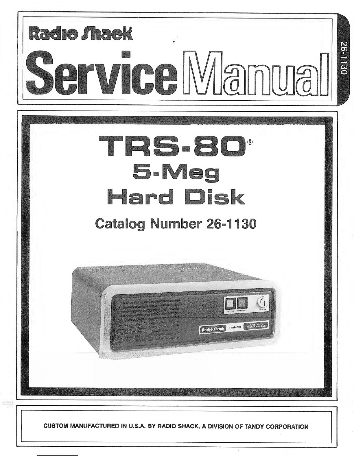
Radio Shack TRS-80 User manual

SfeJ
m
W
M
life
w^m\ mmmm®
rs^joi
G3
LJ5 ^iFr^r^
ar SJ IV
t>C •.^...^.JiH-SittiSJ*
OS'"" ... -'-.-"tll-'*'
f^<" :-;.^i?«i*"»'tSi'*
at-vei:;~!y.»35ivB,i."-it
:"
l^fe?J|
tbeate


5-Meg Hard Disk Service Manual
——TRS-SO ®—;
TRS-80® 5-Meg Hard Disk
Service Manual
Catalog Number 26-1130
Radio HaelC
-i-

5-Meg Hard Disk Service Manual
TRS-SO ®=—
—
TRS-80® 5-Meg Hard Disk Service Manual
Copyright® 1982 Tandy Corporation
All Rights Reserved
Reproduction or use, without express written permission from
Tandy Corporation, of any portion of this manual is
prohibited. While reasonable efforts have been taken in the
preparation of this manual to assure its accuracy, Tandy
Corporation assumes no liability resulting from any errors
or omissions in this manual, or from the use of the
information obtained herein.
Radia/haalc
-2-

5-Meg Hard Disk -rrsea Qn ®Service Manual
Contents
Warnings
1/ Overview „a5
2/ Technical Specifications 7
3/ Connections 11
Model I15
4/ Power-Up and Power-Down 19
5/ Replacement Procedures .23
6/ Maintenance 25
7/ Theory of Operation ...29
Hard Disk Controller Board .... 34
8/ Troubleshooting the Power Supply (Secondary
Drive Only) 47
9/ Printed Circuit Boards 51
10/ Wiring Diagrams 53
11/ Parts List 57
12/ Schematics 63
13/ Supplement 69
Radie/haalf
-3-

5-Meg Hard Disk Service Manual
——TRS-BO ®———————
—
************************************************************
Warnings
************************************************************
Do not move or tilt the Hard Disk Drive unit while the drive
is running. Permanent damage to the drive may occur
resulting in the loss of information or damage to the disk.
Do not drop the Hard Disk Drive unit from any height as
permanent damage to the drive may occur.
Radio JTiaelf
-4-

5-Meg Hard Disk Service Manual
—«——~__«_TRS-SO *
1/ Overview
The TRS-80 5-Meg Hard Disk Unit consists of two
non-removable 5»25-inch disks,, There are four Read/Write
heads (one on each side of each platter) which move towards
or away from the center of the disk as needed.
The Disks and Read/Write heads are fully enclosed in a
sealed chamber .Aspecial air filteration system prevents
dust and other particles, which destroy data, from reaching
the disks oAnother filtering system allows pressure
equalization with the "outside" air pressure.
UNDER NO CIRCUMSTANCES MUST THE CHAMBER BE UNSEALED IN THE
FIELD* ACLASS 100 CLEAN ROOM ENVIRONMENT IS NEEDED FOR
UNDER-THE-BUBBLE REPAIR.
On all Hard Disk Units, flaws in the media are indentified
at the factory before the disk drives are delivered to the
customer .Attached to the bottom of each disk drive unit is
a"Media Error Map". This map identifies the flawed tracks
on that particular unit.
Radio /haek"
-5-

-6-

5-Meg Hard Disk Service Manual
2/ Technical Specifications
Basically, the hard disk unit consists of two platters (or
disks) lying parallel within the unit. There are also four
Read/Write heads, one on each side of each platter .These
heads move towards or away from the center of the disk as
needed.
When aunit is purchased, there will be no more than 3
tracks per head with defects .This will not exceed 8tracks
per drive with defects. Also there will not be any flaws on
Track 0*
Disks/Platters
Heads/Recording Surfaces
Tracks per Inch
Cylinders
Tracks
2
4
254
153
612
Hard Disk
1
Cylinders Tracks Sectors Bytes
153
1612
4
1
19,584 5,013,504
128 32,768
32 8,192
1256
AC Power Requirements
50/60 Hz +/- 0o5 Hz
100/115 VAC installations (90 to 127 V)
200/230 VAC installations (100 to 253 V)
Fuse 2.5 at 250 Volts (Internal)
Power Supply (Primary Drive) Operating Characteristics
Min Typ Max Units
Vin Range
Input Select 115V 90 115 135 Vrms
Input Select 230V 198 230 264 Vrms
Line Frequency 47 50/60 63 Hz
isi^to ff^Qfi
-7-

5-Meg Hard Disk
Output Voltages Vl +5V 4.95
V3 +12V 11.4
V4 -12V 11
Output Current Vl +5V 2.50
V3 +12V .75
V4 -12V .005
Ripple Voltages Vl +5V
V3 +12V
V4 -12V
Efficiency 70
Hold Up Time
Full Load, Low Line 10
Full Load, Norn Line 16
Over-Voltage Protection 5.80
®Service Manual
J©£a —J Volts
12 12 .
6
Volts
-12 -15 Volts
5.0 Amps
2.0 Amps
.10 Amps
50 mv
150 mv
150 mV
6.80
mSec
mSec
Volts
Power Supply (Secondary Drive) Operating Characteristics
Min Typ Max Units
Vin Range
Input Select 115V
Input Select 230V 95
180 115
230 135
264 Vrms
Vrms
Line Frequency 47 50/60 63 Hz
Output Voltages +5V
+12V
-12V
4.75
11.4
-11
5
12
-12 12.6
-15
Volts
Volts
Volts
Output Current +5V
+12V
-12V
.45
.75
.005 2.0
.10
Amps
Amps
Amps
Load Regulation
(measured by varying
load on considered output
from typ to either min or max
rated load) +5V 5
12V -5
-12V -8.3
5
5
25
jo /iaelf
-8-

5-Meg Hard Disk Service Manual
Ripple Voltages +5
12V
-12V
S-QO ®
Efficiency 65
Over-Voltage Protection 5*80
Dimensions
Height
Width
Length
Weight Primary
Secondary
Environment
Ambient Temperature
Relative Humidity
Maximum Wet Bulb
Heat Dissipation
Altitude
50 mV
150 mV
150 mV
%
6.80 Volts
5.50 in (13.97 cm)
14.00 in (35.56 cm)
15o00 in (38.10 cm)
15.5 lbs (33.10 kg)
12.5 lbs (27.5 kg)
50 to 95 degrees F.
(10 to 35degrees C.)
8% to 80%
78% non-condensing
operating: to 6000 feet
(0 to 1829 meters)
storage: -1000 to 12000
feet
(-305 to 3656 meters)
Warm-Up Period
Minimum On Power-Up 2minutes
Minimum to Turn System On
After Turning System Off 15 seconds
Hard Disk Drive
Disk Organization
Tracks per Unit
Tracks per Platter
Sectors per Track
Bytes per Sector
Cylinders per Disk
Average Latency
Rotational Speed
Recording Density
Flux Density
Track Density
Storage Capacity (Hard Disk)
Unformatted
Bytes per Track
612
306
34
256
153
8.34 msec
3600 rpm +/- 1%
7690
7690
254
10400
-9

5-Meg Hard Disk Service Manual
Bytes per Surface 1B59 MEG
Bytes per Drive 6„33 MEG
Formatted
Bytes per Drive 5M(Primary)
5M(Secondary)
Radio /haek"
-10 -

5-Meg Hard Disk Service Manual
—————————TRS-OO ®——-~——-—=_,___
3/ Connections
Connecting Your Primary Drive to aModel III
Be sure all power is OFF,
Notes Master unit does not come with Data Out connectors
.
These are supplied with each secondary unit and require
installations
.
Locate the hard disk expansion cable. Connect one end to
the I/O bus card edge of your Model III. Be sure the cable
exits the rear of the computer so that it won Btbind*
Connect the opposite end of this cable to the COMPUTER IN
connector, located on the rear panel of the primary drive a
Connect the power cord to the primary drive* Plug the other
end into an appropriate AC power source.
Radio Haelf
-11 -

5-Meg Hard Disk ®Service Manual
Figure 1. Back Panel of Hard Disk Drive
1. Computer In (50-pin) Connect the Hard Disk
Expansion Cable from the I/O bus card edge of the
Model III to this jack*
2. Control Out (34-pin) Connect one end of a
Secondary Hard Disk Expansion Cable to this
connector. The other end connects to the first
secondary drive
3. Data Out A(20-pin) Connect one end of the
Data Cable from the first secondary drive to this
connector
.
4eData Out B(20-pin) Connect one end of the
Data Cable from the second secondary drive to this
connector.
5. Data Out C(20-pin) Connect one end of the
Data Cable from the third secondary drive to this
connector.
6oFilter
-12

5-Meg Hard Disk Service Manual
Connecting Secondary Drives
The secondary drives are connected to the computer via the
primary disk drive. The drives must be stacked with the
primary drive on top of the secondary drives.
Locate the secondary hard disk expansion cable. Connect one
end to the Control In jack of the secondary drive and the
other end to the Control Out jack of the previous drive in
the chain. If you have only two hard disk drives, this
connector connects to the primary drive.
If you have another secondary drive* connect the second
secondary hard disk expansion cable to the Control Out jack
and the other end to the Control In jack of the next drive
in the chain.
Locate the data cable. Connect one end to the appropriate
data jack (A for the first secondary drive, Bfor the
second, and Cfor the third). Connect the other end to the
Data In jack on the secondary drive.
Radio /hack
-13 -

5-Meg Hard Disk Service Manual
®
Figure 2. Back Panel of Secondary Hard Disk Drive
1. Control In (34-pin) Connect one end
of aSecondary Hard Disk Expansion
Cable to this jack. The other end
connects to the previous Hard Disk
Drive*
2o Control Out (34-pin) Connect one
end of aSecondary Hard Disk Expansion
Cable to this jack. The other end
connects to the next secondary drive.
3eData In (20-pin) Connect one end of
the Data Cable from the the primary
drive to this jack.
4. Filter
Figure 3»AFully Configured Hard Disk System
14 -

5-Meg Hard Disk Service Manual
———TRS-OO ®
Connecting the Primary Hard Drive to the Model I
To connect the hard disk drives to the Model Iyou need a
Model IKit (Catalog. Number 26-1132). Included in this kit
ares
AModel IAdapter Cable
Three Diskettes?
HARD DISK OPERATING SYSTEM
XTRA
INITIALIZATION
Important Notes The Expansion Interface must be buffered
before the hard disk can be connected to your Model I*
Instructions on how to determine whether the Expansion
Interface is buffered are given next.
There are two types of Buffered Expansion Interfaces. The
first type is recognized by its cables. The flat ribbon
cable between the Expansion Interface and the Keyboard will
have ablack box on it. There will also be a3-wire cable
with adin plug type connector in the middle. See Figure 4
Radio /hade
-15 -

5-Meg Hard Disk Service Manual
Buffered Cable Modification
-Din Plug Modification
Figure 4* Expansion Interface/Keyboard with Buffered Modification
If the computer does not have these cables ,then you must
look inside the Expansion Interface through the bottom
cover
.
Look through the vents on the bottom cover for two rows of
eight memory chip sockets .(The sockets may or may not
contain memory chips *)
If the ROWS of sockets run long ways in the interface —
parallel to the keyboard -- then the computer is buffered
and is ready to be connected to the hard disk* See Figure
5.
-16 -

5-Meg Hard Disk Service Manual
®
Figure 5„Buffered Expansion Interface as Viewed From the Bottom
If the ROWS of sockets run perpendicular to the keyboard ,
the computer is not buffered. See the illustration belows
Figure 6. Non-buffered Expansion Interface Viewed From the Bottom
Radi# #iaett
-17 -

5-Meg Hard Disk ToQ.pn ®Service Manual
Figure 7. Connecting the Hard Disk to Your Model I
lo Locate the Model IAdapter Cable.. One end has a
connector (40-pin) .The other end has ablack box
with acard edge exiting it*
2. Connect the 40-pin connector (the end with the cable)
to the Bus Extension port (also called screen printer
port) of your Expansion Interface. The cable should
exit towards the bottom of the expansion interface.
3. Connect the card edge end to the card edge connector of
the Hard Disk Expansion Cable (50-pin) .The Hard Disk
Expansion Cable should exit the bottom of the
connector.
4. Connect the other end of the Hard Disk Expansion Cable
to the COMPUTER IN connector of the primary hard drive.
The cable should exit towards the bottom of the
connector.
The primary hard disk drive is now connected.
Radi# /haed
18
Other manuals for TRS-80
46
Table of contents
Other Radio Shack Laptop manuals

Radio Shack
Radio Shack 60-2632 User manual

Radio Shack
Radio Shack TRS-80 4P Gate Array Reference manual

Radio Shack
Radio Shack TRS-80 Model 100 User manual

Radio Shack
Radio Shack 60-2642 User manual

Radio Shack
Radio Shack TRS-80 Model 100 User manual

Radio Shack
Radio Shack TANDY 102 User manual

Radio Shack
Radio Shack TRS-80 Model 100 Product manual

Radio Shack
Radio Shack Tandy 200 Product manual

Radio Shack
Radio Shack TRS-80 Model 100 User manual