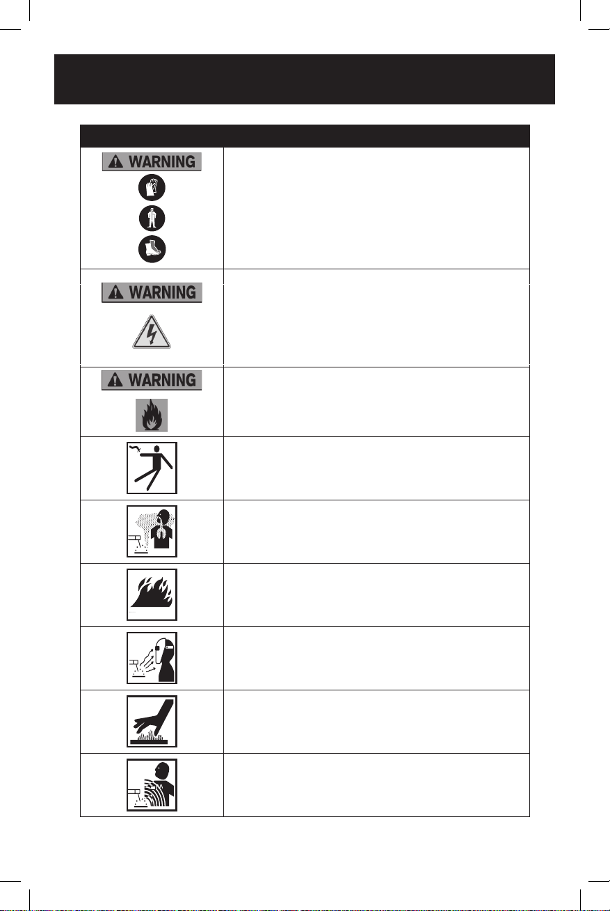
RADLEY 1150-000 User manual

229683
EXTREME 80
OWNER’S MANUAL
3 Year Limited Warranty on tool

Input Voltage 1ph 120V
Input Power (KVA) 2.4
Input Current (A) 20
Output Current Range (A) 20-75A
Max. Output Current (A) 75A/23V
No-load Voltage (V) 70
Rated Duty Cycle 40% at 75A
85
Power Factor 0.65
Protection Class IP21S
Insulation Class H
Tool Dimensions 12 3/8" x 4 x 6 15/16" (31.5 x 10.2 x 17.6cm)
Net Weight 6.61lb/3kg
Input Power Cord Length 2m/6.5ft
Welding Cable Length 1.5m/4.9ft
Earth Clamp Length 1.5m/4.9ft
Call us on our toll free customer support line:
1-866-349-8665 (Monday through Friday 9am - 5pm Eastern Time)
•Technical questions
•Replacement parts
•Parts missing from package

1150-000
INVERTER STICK WELDER KIT
2
TBE F CNET
...........................................................................................................1
................................................................................................................... 2
......................................................................................................
................................................................................
.......................................................................................................................
........................................................................................ 10
................................................................................................................................ 11
...............................................................................................................................12
...................................................................................................................16
......................................................................................................................
................................................................................................................................18
Warranty .................................................................................................................................18

3
GNRL SFT ANNS
IMPORTANT SAFETY INSTRUCTIONS
Read and understand all safety and operational instructions. Failure to follow the
safety rules listed below and other basic safety precautions may result in serious
personal injury. Keep this manual, sales receipts and applicable warranty forms
for future reference.
SAFETY SYMBOLS
SYMBOL MEANING
DANGER WILL
WARNINGMAY
CAUTIONMAY
NOTICE or a CAUTION
MAY
ALWAYS WEAR EYE PROTECTION THAT CONFORMS WITH CSA
Z94.3 or ANSI SAFETY STANDARD Z87.1
Non-compliant eyewear can cause serious injury if broken during
the operation of a power tool.
WEAR A DUST MASK THAT IS DESIGNED TO BE USED WHEN
OPERATING A POWER TOOL IN A DUSTY ENVIRONMENT.

1150-000
INVERTER STICK WELDER KIT
4
SYMBOL MEANING
Always wear non-slip gloves that fit properly to protect your hands
and to help you grip the tool.
Always wear sturdy clothing with long sleeves and long pants.
Never operate the tool while wearing shorts, short sleeve shirt or
while shirtless.
Always wear non-slip safety boots to prevent foot injuries and slipping
that could cause loss of control of the tool.
To avoid electrical hazards, fire hazards or damage to the tool,
use proper circuit protection.
WARNING: Ventilation openings in batteries and chargers must
always be open to allow cooling air to circulate freely. Air vents that
are blocked, restricted or covered may result in the battery or charger
overheating. Overheating may lead to damage to the tool or cause a
fire, resulting in possible serious injury.
ELECTRIC SHOCK CAN KILL
FUMES AND GASES
FIRE HAZARDS
ARC RAYS
HOT MATERIALS
MAGNETIC FIELDS
This machine is wired at the factory for 120V AC operations
(Plug will only fit one way). Plug the power cord into a properly
grounded, GFCI protected 120V AC receptacle that
matches the plug. The circuit must be equipped with delayed
action-type circuit breaker or fuses. To avoid shock or fire, replace
power cord immediately if it is worn, cut or damaged in any way.

5
WARNING:
OWNER’S MANUAL.
TRAINED OPERATORS ONLY.
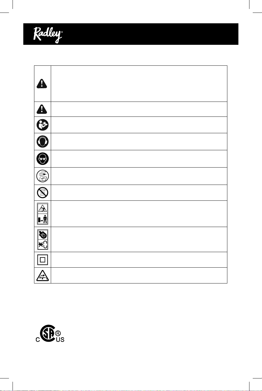
DANGEROUS ENVIRONMENTS.
MENTAL ALERTNESS REQUIRED.
ELECTRICAL EQUIPMENT INJURY RISKS.
DISCONNECT POWER FIRST.
EYE PROTECTION.
WEARING PROPER APPAREL.
HAZARDOUS DUST.
HEARING PROTECTION.
REMOVE ADJUSTING TOOLS.
USE CORRECT TOOL FOR THE JOB.
AWKWARD POSITIONS.
CHILDREN & BYSTANDERS.

1150-000
INVERTER STICK WELDER KIT
6
GUARDS & COVERS.
FORCING MACHINERY.
NEVER STAND ON MACHINE.
STABLE MACHINE.
USE RECOMMENDED ACCESSORIES.
UNATTENDED OPERATION.
MAINTAIN WITH CARE.
DAMAGED PARTS.
MAINTAIN POWER CORDS.
SERVICE
•

7
SEFC SFT ANNS FR WLES
WARNING:
In order to avoid mistakes that could cause serious injury, read the following steps
carefully and understand them thoroughly before using this welder.
WELDING FUMES.
WELDING IN A CONFINED SPACE CAN BE HAZARDOUS.
ELECTRIC SHOCK. DO NOT
PREVENT FIRES.
WORKING AREA.
PROTECT BODY FROM ARC BURNS, SPARKS, AND SPATTER. Wear correct and
HANDLING GAS CYLINDERS.

1150-000
INVERTER STICK WELDER KIT
8
PROTECT GAS CYLINDERS FROM HEAT OR DAMAGE.
or death.
ELECTRIC AND MAGNETIC FIELDS (EMF).
EXPERIENCING DIFFICULTIES.
SAVE THIS USER MANUAL
WARNING:
MISUSE or failure to follow the safety rules stated in this instruction manual may cause
serious personal injury.

9
SAFETY SYMBOLS
WARNING:
EXTREME 80

1150-000
INVERTER STICK WELDER KIT
10
KO OR ECMR FU CR EDR
Attention
FUNCTIONS
1
2
4
5
7
6
3
20 75
60
70
45
30
DC Inverter Arc Welder

11
ASML
connected to anode and ground cable connected to cathode.
.
.
each end.

1150-000
INVERTER STICK WELDER KIT
12
ELECTRODE SELECTION
-
heat of the arc between the rod and the grounded metal melts the electrode and the
— E6013 60,000 PSI tensile strength used for poor fit-up applications.
— E7018 70,000 PSI tensile strength
This welder is capable of welding with 1/16" (1.6 mm), and 5/64" (2 mm) and 3/32" (2.4
mm) electrodes.
WELDING POSITION
easier, faster, and allows for better penetration. If possible, the workpiece should be
PREPARING THE JOINT
Before welding, the surface of the workpiece must be free of dirt, rust, scale, oil or paint,
which create a brittle and porous weld. If the base metal pieces to be joined are thick
or heavy, it may be necessary to bevel the edges with a metal grinder. The correct bevel
should be around 60 degrees. See following picture:
images for more information:

13
GROUND CLAMP CONNECTION
SELECTING THE PROPER ELECTRODE
the correct electrode.
1. WHEN THE PROPER ROD IS USED:
2. WHEN A ROD TOO SMALL IS USED:
3. WHEN THE ROD IS TOO LARGE:
WARNING!
THIS WELDING MACHINE MUST BE CONNECTED TO POWER SOURCE IN
ACCORDANCE WITH APPLICABLE ELECTRICAL CODES.

1150-000
INVERTER STICK WELDER KIT
14
1. SETTING THE AMPERAGE CONTROL
5/64, 3/32 electrodes.
There is no golden rule that determines the exact amperage required for every situation.
It is best to test your welds on scrap metal which matches the metals you intend to work
with to determine correct setting for your job. The electrode type and the thickness
of the workpiece metal determine the amount of heat needed in the welding process.
Heavier and thicker metals require more voltage (amperage), whereas lighter and thinner
metals require less voltage (amperage).
2. WELDING TECHNIQUES
The best way to teach yourself how to weld is with short periods of practice at regular
intervals. All practice welds should be done on scrap metal that can be discarded. Do
that your practice welds are of good appearance and free of slag or gas inclusions.
2.1 HOLDING THE ELECTRODE
The best way to grip the electrode holder is the way that feels most comfortable to
you. To position the electrode to the workpiece when striking the initial arc it may be
necessary to hold the electrode perpendicular to the workpiece. Once the arc is started
the angle of the electrode in relation to the workpiece should be between 10 and 30
degrees. This will allow for good penetration, with minimal spatter.
2.2 STRIKING THE ARC
Scratch the work piece with the end of the electrode to
start an arc and then raise it quickly to about a 1/8" gap
between the rod and the workpiece.
See the following picture: It is important that the
gap be maintained during the welding process and
it should be neither too wide nor too narrow. If too
narrow, the rod will stick to the workpiece. If too
wide, the arc will be extinguished. It needs much
practice to maintain the gap. Beginners may usually
get sticking or arc extinguishing. When the rod sticks
to the workpiece, gently rock it back and forth to
make it release. If not, the circuit will be shorted, and
it will overload the welder. A good arc is accompanied
by a crisp, crackling sound. The sound is similar to
that made by eggs frying. To lay a weld bead, only
2 movements are required; downward and in the
direction the weld is to be laid, as in the following

15
2.3 TYPES OF WELD BEAD
2.4 WELDING POSITION
2.5 JUDGE A GOOD WELD BEAD
D. Ideal weld.
2.6 FINISH THE BEAD

1150-000
INVERTER STICK WELDER KIT
16
WARNING!
•
TOBEHON
•
•
•
•

17
EPDD VE

1150-000
INVERTER STICK WELDER KIT
18
PRS LS
WARNING:
Key # Part #
1 1
2 1
1
4 1
1
6 1
1
8 1
1
10 Knob 1
11 2
12 2
1
14 Fan 1
1
16 1
1
18 Power Cable 1
4
WRAT
RADLEY STICK WELDER
If this Radley tool fails due to a defect in material or workmanship within three
years from the date of purchase, return it to any Home Hardware store with the
original bill of sale for exchange. Two year warranty for the battery and charger. This
warranty does not include expendable parts including but not limited to blades,
brushes, belts, light bulbs.
This warranty covers defects in material or workmanship only. It does not cover
normal wear and tear, failure due to abuse/misuse, or defects caused by careless
or accidental mishandling. If this Radley product is used for commercial or rental
purposes, this warranty does not apply.

19
Table of contents
Popular Inverter manuals by other brands

Leroy-Somer
Leroy-Somer POWERDRIVE MD2CS Installation and Maintenance

TECO
TECO A510s instruction manual

GE
GE 20 kW Home Installation and start-up manual

Sunways
Sunways NT 2600 user manual

DEVA Broadcast
DEVA Broadcast DB9000-STC instruction manual

Fortress Power
Fortress Power FP-ENVY-8K Installation & user manual