Radwin WinLink 1000 User manual

W
i
n
Lin
k
™100
0
Installation and Operation Manual
Point-to-Point Wireless
Product Family
Revision 3.0


WinLink 1000
Point-to-Point Wireless TDM/IP Revision 3.0
Installation and Operation Manual
Notice
This manual contains information that is proprietary to RADWin Ltd. ("RADWIN"). No
part of this publication may be reproduced in any form whatsoever without prior written
approval by RADWIN Ltd.
Right, title and interest, all information, copyrights, patents, know-how, trade secrets
and other intellectual property or other proprietary rights relating to this manual and to
the WinLink 1000 and any software components contained therein are proprietary
products of RADWIN protected under international copyright law and shall be and
remain solely with RADWIN.
WinLink 1000 is a registered trademark of RADWIN. No right, license, or interest to such
trademark is granted hereunder, and you agree that no such right, license, or interest
shall be asserted by you with respect to such trademark.
You shall not copy, reverse compile or reverse assemble all or any portion of the Manual
or the WinLink 1000. You are prohibited from, and shall not, directly or indirectly,
develop, market, distribute, license, or sell any product that supports substantially
similar functionality as the WinLink 1000, based on or derived in any way from the
WinLink 1000. Your undertaking in this paragraph shall survive the termination of this
Agreement.
This Agreement is effective upon your opening of the WinLink 1000 package and shall
continue until terminated. RADWIN may terminate this Agreement upon the breach by
you of any term hereof. Upon such termination by RADWIN, you agree to return to
RADWIN the WinLink 1000 and all copies and portions thereof.

For further information contact RADWIN at the address below or contact your local
distributor.
International Headquarters RADWIN Ltd.
32 Habarzel Street
Tel Aviv 69710 Israel
Tel: 972-3-7662900
Fax: 972-3-7662902
E-mail: [email protected]
U.S. Headquarters RADWIN Inc.
900 Corporate Drive
Mahwah, NJ 07430 USA
Tel: (201) 529-1100Fax: (201) 529-
5777
E-mail: [email protected]om

FCC-15 User Information
This equipment has been tested and found to comply with the limits for a
Class B digital device, pursuant to Part 15 of the FCC Rules. These limits
are designed to provide reasonable protection against harmful interference
in a residential installation. This equipment generates, uses and can
radiate radio frequency energy and, if not installed and used in accordance
with the instructions, may cause harmful interference to radio
communications. However, there is no guarantee that interference will not
occur in a particular installation. If this equipment does cause harmful
interference to radio or television reception, which can be determined by
turning the equipment off and on, the user is encouraged to try to correct
the interference by one or more of the following measures:
-- Reorient or relocate the receiving antenna.
-- Increase the separation between the equipment and receiver.
-- Connect the equipment into an outlet on a circuit different
from that to which the receiver is connected.
Consult the dealer or an experienced radio/TV technician for help.
Changes or modifications to this equipment not expressly approved by the party
responsible for compliance (RADWIN) could void the user’s authority to operate the
equipment.
It is the responsibility of the installer to ensure that when using the
outdoor antenna kits in the United States (or where FCC rules apply),
only those antennas certified with the product are used. The use of
any antenna other than those certified with the product is expressly
forbidden in accordance to FCC rules CFR47 part 15.204.
Warning

Installing WinLink 1000 Units 1
Quick Start Guide
Installation of WinLink 1000 should be carried out only by a qualified
technician. If you are familiar with WinLink 1000, use this guide to
prepare the units for operation.
1. Installing WinLink 1000 Units
ODU Package Contents:
•ODU
•Mast/Wall mounting kit
•WinLink 1000 Management software installation CD
•Mounting instructions
•Spare RJ-45 connector
•ODU to IDU cable at length ordered (optional)
IDU-E Package Contents:
•IDU-E
•110V/240V adaptor
•IDU wall-mounting drilling template
•Spare RJ-45 connector
(Optional) IDU-C Package Contents:
•IDU-C
•For AC model, 110v/240 VAC with 3-prong connector cable
•For DC model, -48 VDC with 3-pin terminal block connector (green)
•IDU standard 1-U, 19” carrier rack
•Spare RJ-45 connector
Equipment Required:
•RJ-45 crimp tool (If pre-assembled cable is not used)

Quick Start Guide WinLink 1000 Installation and Operation Manual
2 Installing WinLink 1000 Units
•Drill (for wall mounting only)
•IDU and ODU grounding cable
•13 mm or 1/2″socket spanner
•ODU to IDU cable if not ordered (Outdoor class, CAT-5e, 4 twisted
pairs)
•Cable ties
•Laptop running Windows 2000 or Windows XP
Before the installation
1. Install the WinLink 1000 software on the laptop.
2. Verify that all equipment and tools are available.
Performing Installation
ÎTo install the ODU:
1. At site A, route the ODU cable from the ODU location (on the roof) to
the IDU location (inside the building). The maximum length is 100m.
2. Mount the ODU unit to the mast or wall, using the mounting kit.
3. Connect the RJ-45 connectors to both ends of the cable, use the
pinout table and diagram below:
IDU RJ-45 Wire Color Function ODU RJ-45
1 White/Green Ethernet (RxN) 1
Twisted 2 Green Ethernet (RxT) 2
3 White/Orange Ethernet (TxT) 3
Twisted 4 Blue Power (+) 4
5 White\Blue Power (+) 5
Twisted 6 Orange Ethernet (TxN) 6
7 White/Brown
Power (−) 7
Twisted 8 Brown
Power (−) 8
4. Secure the ODU and ground cables to the mast or brackets using
cable ties.
5. Repeat the procedure at site B.

WinLink 1000 Installation and Operation Manual Quick Start Guide
Installing WinLink 1000 Units 3
ÎTo align the ODU:
1. Connect power to the IDU.
Do not stand in front of a live outdoor unit.
The antenna used for this transmitter must be installed to provide a
separation distance of at least 200 cm from all persons and must not be
co-located or operating in conjunction with any other antenna or
transmitter.
2. Align the site A ODU in the direction of the site B ODU.
3. Align the site B ODU in the direction of the site A ODU.
4. Alternating between each site, turn each ODU slowly listening to the buzzer
beep sequence until optimal alignment is achieved.
5. Secure the site Aand site BODUs to the mast/wall.
6. Monitor the link quality for about 15 minutes to verify stability.
7. Connect the management station to one of the two IDUs in the link.
8. Start the WINLink Manager application.
9. Open the installation wizard and follow the installation steps.
10.After selection of the radio channel and the link rate, verify that the
link quality bar in the WinLink manager is within the green range for
TDM service and within the yellow range for Ethernet service.
Achieve the best possible link quality values. In case of radio link loss,
verify the ODU alignment, or change the radio channel in both sides of
the link. When the radio link resumes continue the installation process.
Connecting User Equipment
ÎTo connect user equipment to the IDU:
1. Connect the user equipment (such as PBX) to the IDU RJ-45 port
designated Trunk:
On the rear panel of the IDU-E.
On the front panel of the IDC-C,
2. Connect user hub/router or any other compatible device to the IDU
RJ-45 port designated LAN:
On the rear panel of the IDU-E.
Not
e
Warning

Quick Start Guide WinLink 1000 Installation and Operation Manual
4 Operating WinLink 1000
On the front panel of the IDU-C.
IDU-C has an integrated LAN switch that provide 2 port of 10/100BaseT.
The Integrated LAN switch is not support spanning tree.
The two LAN ports can be connected to 2 separated LAN segments but
connection of both LAN ports to the same LAN segment will create a loop
that fluid the network. Therefore, this configuration is prohibited.
2. Operating WinLink 1000
WinLink 1000 requires no operator attention once installed, with the
exception of occasional monitoring of front panel indicators and statistics
data. Intervention is only required when WinLink 1000 must be
configured to its operational requirements or diagnostic tests are
performed:
Normal Indications
Upon turning on WinLink 1000, the PWR LED in the front panel lights to
indicate that WinLink 1000 is on. The table below shows the correct
status of the indicators after power-up.
Indicator Color Status
PWR Green On (only on IDU-E)
IDU Orange
Green
Blinks for short duration during startup
Blinking slowly shows normal operation
ODU Green Blinking slowly shows normal operation
AIR I/F Orange
Green
Blinks for short duration during startup
Blinking slowly shows normal operation
SERVICE Green Blinking slowly shows normal operation
OFF when SERVICE selected is Ethernet only
Note

WinLink 1000 Installation and Operation Manual Quick Start Guide
Operating WinLink 1000 5
Troubleshooting
If the WinLink 1000 is not operational, determine the cause and solution
from the table below.
Led Status Remedy
PWR Off For the IDU-E, check that AC adapter is connected
to the IDU and the AC power outlet.
IDU Orange Check that the IDU/ODU cable is properly wired
and connected.
ODU Red Check that the IDU/ODU cable is properly wired
and connected.
Orange Complete the installation procedure from the
management software.
AIR I/F
Red Check the ODU Antenna alignment. Check that
the radio configuration of both site A and site B
units are the same (channel and SSID).
Off Check the TDM service configuration in the NMS.
Orange Check that the system is not in loopback mode.
Check the site B IDU ports and cables and site B
external equipment.
SVC.
Red Check the site A IDU ports, cables and external
equipment.

Contents
Chapter 1. Introduction
1.1 Overview .................................................................................................. 1-1
Application....................................................................................................... 1-1
Features........................................................................................................... 1-2
1.2 Physical Description.................................................................................. 1-4
Chapter 2. Installation and Setup
2.1 WinLink 1000 System ............................................................................... 2-1
2.2 Site Requirements and Prerequisites ......................................................... 2-2
2.3 Package Contents ..................................................................................... 2-2
2.4 Installation and Setup ............................................................................... 2-3
Mounting the ODU ........................................................................................... 2-4
Connecting the ODU to the IDU ........................................................................ 2-5
Connecting the Power ...................................................................................... 2-6
Installing WinLink 1000 Management Software ................................................. 2-7
Aligning the WinLink 1000 ODUs...................................................................... 2-9
Installing the Link........................................................................................... 2-10
Connecting the User Equipment ..................................................................... 2-18
Chapter 3. Configuration
3.1 Performing Configuration of WinLink 1000 ............................................... 3-1
Configuring Service Parameters ...................................................................... 3-10
Editing the Configuration Parameters ............................................................. 3-13
Changing the Transmit Power......................................................................... 3-15
Defining the Management Addresses.............................................................. 3-15
3.2 Bridge Configuration .............................................................................. 3-17
Detailed description ....................................................................................... 3-17
ODU Bridge Mode........................................................................................... 3-18
IDU Aging time............................................................................................... 3-18
Chapter 4. Operation
4.1 Indicators ................................................................................................. 4-1
Panel Indicators................................................................................................ 4-1
Connector LED Indicators ................................................................................. 4-2
Installation and Operation Manual i

Table of Contents
4.2 Operating WinLink 1000 ........................................................................... 4-3
Turning On WinLink 1000................................................................................. 4-3
Normal Indications ........................................................................................... 4-4
Turning Off WinLink 1000 ................................................................................ 4-4
Changing the Password .................................................................................... 4-4
4.3 Managing WinLink 1000 ........................................................................... 4-5
Resetting WinLink 1000.................................................................................... 4-7
Saving WinLink 1000 Configuration in a File ..................................................... 4-7
Restoring a Configuration File .......................................................................... 4-8
Displaying the WinLink 1000 Inventory............................................................. 4-8
Chapter 5. Diagnostics and Troubleshooting
5.1 Error Detection and Alarms....................................................................... 5-1
5.2 Collecting and Saving Statistics.................................................................5-2
5.3 Running Diagnostic Loopbacks .................................................................5-3
Local External Loopback................................................................................... 5-4
Remote Internal Loopback ................................................................................ 5-5
Remote External Loopback ............................................................................... 5-5
Local Internal Loopback.................................................................................... 5-6
5.4 Troubleshooting ....................................................................................... 5-6
5.5 Frequently Asked Questions ..................................................................... 5-8
Air Interface ..................................................................................................... 5-8
Management .................................................................................................... 5-9
Services.......................................................................................................... 5-10
Antennas and Cables...................................................................................... 5-10
Competitve .................................................................................................... 5-10
5.6 Technical Support................................................................................... 5-11
Appendix A. Wiring Specifications
Appendix B. Mast and Wall Installation
Appendix C. Link Budget Calculator
Appendix D. TDM Clock Configuration
ii WinLink-1000 Installation and Operation Manual

Table of Contents
List of Figures
1-1. Typical Application.......................................................................................... 1-1
1-2. WinLink 1000 Units ......................................................................................... 1-4
2-1. Typical Installation Diagram ............................................................................ 2-4
2-2. IDUs connector panels..................................................................................... 2-6
2-3. Login Screen ................................................................................................... 2-8
2-4. Login vial Local Connection Screen .................................................................. 2-9
2-5. Main Menu ...................................................................................................... 2-9
2-6. Beeper Sequence for ODU Alignment ............................................................. 2-10
2-7. Link Installation Wizard ................................................................................. 2-11
2-8. Installation Wizard, System dialog box ..........................................................2-12
2-9. Installation Wizard, Channel Select dialog box............................................... 2-13
2-10. Installation Wizard, Channel Select dialog box (Automatic Channel Select
enabled) ........................................................................................................... 2-14
2-11. Installation Wizard, Channel Select dialog box (Supporting DFS, ETSI standard
requirement) .................................................................................................... 2-15
2-12. Installation Wizard, Rates dialog box ........................................................... 2-16
2-13. Installation Wizard, Services dialog box ....................................................... 2-17
2-14. Installation Wizard, Finish Screen ................................................................ 2-18
3-1. WinLink Manager Main Menu ........................................................................... 3-2
3-2. Configuration Link Wizard ............................................................................... 3-3
3-3. Link Configuration, System dialog box ............................................................ 3-4
3-4. Link Configuration, Channel select dialog box................................................. 3-5
3-5. Link Configuration, Channel select dialog box with Automatic Channel select .3-6
3-6. Link Configuration, Channel select dialog box with DFS .................................. 3-7
3-7. Channel reselection confirmation dialog box ...................................................3-8
3-8. Reselection process......................................................................................... 3-8
3-9. Reselection process "channel not active in list" ................................................ 3-9
3-10. Air Interface Rate select Dialog Box ............................................................... 3-9
3-11. Service Parameters Dialog Box, E1/T1 Interface...........................................3-11
3-12. Service Parameters Dialog Box, Ethernet only Interface ................................3-12
3-13. Configuration Link, Finish screen ................................................................3-13
3-14. Configuration Dialog Box ............................................................................ 3-14
3-15. Changing the Transmit Power...................................................................... 3-15
3-16. Configuration, Management ........................................................................ 3-16
3-17. Site configuration dialog box....................................................................... 3-17
Installation and Operation Manual iii

Table of Contents
3-18. Hub mode selected ..................................................................................... 3-19
3-19. Hub mode, no IDU Aging.............................................................................3-20
3-20. Bridge mode, no IDU Aging ......................................................................... 3-21
4-1. IDU Panels LEDs .............................................................................................. 4-1
4-2. Main Menu, Wireless Link is Active ..................................................................4-5
4-3. WinLink 1000 Inventory...................................................................................4-9
5-1. Preferences Dialog Box, Event Log Tab ............................................................ 5-3
5-2. Loopbacks Dialog Box ..................................................................................... 5-4
5-3. Local External Loopback..................................................................................5-5
5-4. Remote Internal Loopback ............................................................................... 5-5
5-5. Remote External Loopback .............................................................................. 5-6
5-6. Local Internal Loopback................................................................................... 5-6
iv WinLink-1000 Installation and Operation Manual

Table of Contents
List of Tables
4-1. IDU Panel LEDs ................................................................................................ 4-2
4-2. WAN/LAN LEDs................................................................................................ 4-2
4-3. TDM Traffic Indicators..................................................................................... 4-2
4-4. WinLink 1000 Indicators at Startup..................................................................4-4
5-1. WinLink 1000 Alarms and Information Messages .............................................5-2
5-2. Troubleshooting with WinLink 1000 LEDs........................................................ 5-7
Table A-1. ODU-IDU Cable Connector Pinout ..........................................................A-1
Table A-2. E1/T1 Connector Pinout ........................................................................A-2
Table A-3. Fast Ethernet Connector Pinout..............................................................A-2
Table A-4. Terminal Block 3-pin -48VDC................................................................A-3
Table A-5. Alarm Connector (Dry-Contact) .............................................................A-3
Installation and Operation Manual v

Chapter 1
Introduction
1.1 Overview
WinLink 1000 is a carrier-class, high capacity, Point-to-Point
broadband wireless transmission system. WinLink 1000 combines
legacy TDM and Ethernet services over 2.4GHz, 4.9GHz, and 5.xGHz
license-exempt bands and is suitable for deployment in FCC, ESTI, or
CSA regulated countries. The system provides up to 48 Mbps wireless
link and supports ranges of up to 80 km (50 miles).
Application
Figure 1-1
illustrates a typical point-to-point application of two
WinLink 1000 units.
Figure 1-1. Typical Application
Overview 1-1

Chapter 1 Introduction WinLink 1000 Installation and Operation Manual
Features
Wireless Link
WinLink 1000 delivers up to 48 Mbps data rate for Ethernet and E1/T1
traffic. The system supports a variety of spectrum bands and can be
configured to operate in any channel on the band with a carrier step
resolution of 5 MHz.
WinLink 1000 operation complies with ETSI, CSA and the FCC 47CFR
Part 15 and subpart C and E requirements.
WinLink 1000 employs Time Division Duplex (TDD) transmission. This
technology simplifies the installation and configuration procedure.
There is no need to plan and to allocate separate channels for the
uplink and downlink data streams.
Operation over 2.4GHz, 4.9 GHz, and 5.x GHz bands is not affected by
harsh weather conditions, such as fog, heavy rain etc.
LAN Interface
The WinLink 1000 LAN port provides 10/100BaseT interfaces with auto
negotiation and transparent VLAN support. Traffic handling is provided
by a MAC-level self-learning bridge.
TDM Interface
The WinLink 1000 TDM interface accepts E1 or T1 traffic, supporting
the following:
•Unframed operation (E1 and T1)
•AMI and B8ZS zero suppression (T1).
Management
WinLink 1000 has full local and remote management capabilities. The
user-friendly SNMP-based management tool provides full end-to-end
configuration, event log and performance monitoring capabilities.
Diagnostics and Performance Monitoring
WinLink 1000 supports activating local and remote loopbacks on E1/T1
links.
1-2 Overview

WinLink 1000 Installation and Operation Manual Chapter 1 Introduction
WinLink 1000 constantly monitors the data transmission process,
evaluates received signal strength, and signal quality. It also monitors
received traffic and frame rate (FPS) for local and remote units.
Optional External Antenna
WinLink 1000 supports configuration of an external antennae. In this
configuration, the radio supplies an N-type connector that connects
through a coax cable to the external antenna.
An external antenna can extend the range of the link, and in some
cases, it might help to reduce environmental interferences. Various
external antennae are available for the WinLink 1000 operating
frequencies.
For example, an optional flat panel 28 dBi external antenna increases
the operation range of WinLink 1000 up to 80 km (50 miles).
Overview 1-3

Chapter 1 Introduction WinLink 1000 Installation and Operation Manual
1.2 Physical Description
WinLink 1000 system consists of an Outdoor Unit (ODU) and an Indoor
Unit (IDU).
Figure 1-2
illustrates a WinLink 1000 unit assembly.
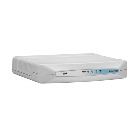
Figure 1-2. WinLink 1000 Units
IDU-E
The IDU-E front panel includes five LEDs that display the status of
E1/T1 and LAN, wireless link, self-test results, ODU-to-IDU link, and
power status. For a detailed description of the front panel LEDs, see
Chapter 4
.
The rear panel of the indoor unit (IDU) includes the power, WAN, LAN
and E1/T1, and ODU connectors. The rear panel LEDs are described in
Chapter 4
, and the wiring specifications detailed in
Appendix A
.
IDU-C
The IDU-C front panel includes four LEDs that display the status of
E1/T1and, wireless link, self-test results, and ODU-to-IDU link. For a
detailed description of the front panel LEDs, see
Chapter 4
.
1-4 Physical Description

WinLink 1000 Installation and Operation Manual Chapter 1 Introduction
Technical Specifications
Air-Interface
Technology
OFDM
Frequency Band
2.400–2.4835 GHz FCC/ETSI
2.416–2.4835 GHz (Israel)
4.940-4.990 GHz FCC
5.250–5.350 GHz FCC
5.470–5.725 GHz FCC/ETSI
5.725–5.850 GHz FCC
Range
Up to 80 km (50 miles)
Duplexing Method
Time Division Duplex (TDD)
Capacity
Configurable up to 48 Mbps
Modulation
OFDM - BPSK, QPSK, 16QAM, 64QAM
Channel setting
Resolution
5 MHz
Transmitter Power
17 dBm max, for 4.9GHz 12.8 dBm max.
(Blocked by product SW and can not be
changed).
ODU Installation
Mast or wall mounting
LAN Interface
PHY IF
Up to 2 x 10/100BaseT, auto-sensing
Framing/Coding
IEEE 802.3/U
Bridging
Self-learning, up to 2000 MAC addresses
Line Impedance
100Ω
VLAN Support
Transparent
Connector
RJ-45
E1 Interface
Data Rate
1, 2, 4 x E1
Unframed (Transparent) 2.048 MHz
Line Interface
HDB3
Connector
RJ-45
T1 Interface
Data Rate
1, 2, 4 x T1
Unframed (Transparent) 1.544 MHz
Physical Description 1-5
Other manuals for WinLink 1000
4
Table of contents
Other Radwin Microphone System manuals