Rain Bird WR2 User manual

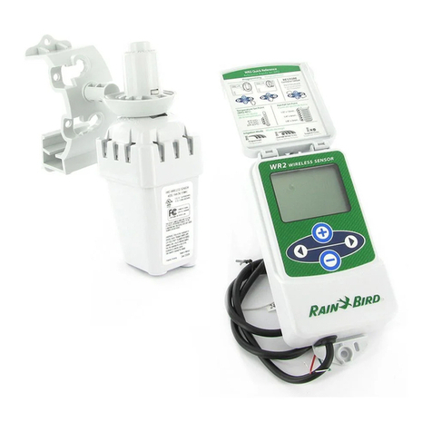
WR2
Wireless
S
ensor
User Manual
M
anual
del usuario Manuel
de
l
’utilisa
t
eur
WR2 user manual
(637469 -01)
EN
ESMX
FRCA.indd 1 8/17/2017
3:44:18
AM

EN
ES
page 11
FR
page 22
C
ontents
Safety
I
nf
orma
tion
.......................................................... .
1
I
n
t
er
f
er
enc
e
WithOther Electronic
Devices....................... .
1
I
n
tr
o
duc
tion
.................................................................. .
1
WR 2
C
omp
onents
........................................................... .
2
WR 2
Benefits
............................................................................... .
2
Mounting the
C
on
tr
oller
I
n
t
erfac
e
.................................... .
2
Wiring
the
C
on
tr
oller
I
n
t
erfac
e
to the
I
rriga
tion
C
on
tr
oller
.. .
3
I
nitial Power Up
.............................................................. .
4
C
on
tr
oller
I
n
t
erfac
e
Display
I
c
ons
..................................... .
4
Sensor Status
............................................................. .
4
Environmental Conditions
............................................ .
4
I
rr
iga
tion
Modes
......................................................... .
5
Synchronize the Sensor and
C
on
tr
oller
I
n
t
erfac
e
................ .
5
Programming the Set Points
............................................ .
6
Rainfall
Set Point
......................................................... .
6
T
emperatur
e
Set Point
(R
ain/F
r
eez
e
Sensor
only) ............... .
6
Programming
I
rriga
tion
Modes
........................................ .
6
Saving, Resetting and Restoring Settings
.......................... .
7
Save Contractor Default Settings
.................................... .
7
R
eset
Contractor Default Settings
................................... .
7
R
est
or
e
Contractor Default Settings
................................ .
7
R
est
or
e
Standard Setting
.............................................. .
7
Select the Sensor
L
o
c
a
tion
............................................... .
7
Sensor Mounting
I
nstruc
tions
.......................................... .
8
Using Multiple
C
on
tr
oller
I
n
t
erfac
e
Unit s
........................... .
8
WR 2
Wireless Sensor Alerts
&
Troublesh ooting
................... .
9
Replacement or Spare Parts
............................................. .
9
Declaration of
C
onf
ormit
y
............................................. .
10
WR2 user manual
(637469 -01)
EN
ESMX
FRCA.indd 2 8/17/2017
3:44:19
AM
F
!
!
!
!
Safety
I
nf
orma
tion
Symbols used in this manual:
Symbol alerts the user
t
o
the
presence
of
un-insula
t
ed
“dangerous voltage”
within
the
pr
o
duc
t
’
s
enclosur
e
that may be of
sufficien
t
magnitude
to
constitute
a risk
of electric
sho
ck
.
Symbol alerts the user
t
o
the
presence
of
imp
or
tan
t
operating or
main
t
enanc
e
(servicing) instr
uc
tions
.
I
n
t
erfer
enc
e
With
O
ther
E
lec
tr
onicDe
vic
es
Al l
radio
transmitters
broadcast
ener
gy
through
the
air. This
energy may interfere
with
other electronic devices in close proximity
t
o
the
WR 2 Wireles s S
ensor
.
To
lower the
risk
of
electronic in
t
er
f
er
enc
e:
•
Do not place sensitive
electronics
(c
omput
ers
,
t
elephones
,
r
adios
,
et
c
.)
in close proximity to the
C
on
tr
oller
I
n
t
er
fac
e
or
S
ensor
.
•
Use clip-on ferrite sleeves on
the
connection
or power cables of
aff
ec
t
ed
electronic device(s).
THE IRRIG ATION
C
ONT R
OLLER
/
TIMER SHOULD BE ISO L
A
TED
VIA A CI RCUIT BREAKER
OR
CU TOFF
SWITCH.
BAT TERIES REM O VED FR
OM
THE SENSOR
SHOULD
BE DISPOSED OF
IN
ACC OR DANCE WITH
L
OC
AL
REGULATIONS.
CHANGES OR MODIFI C
ATIONS
NOT EXPRESS LY
APPROVED
BY THE PAR TY
RESPONSIBLE
FOR COMPLIANCE
C
OULD
VOID THE USE R’S
A
UTHORI T
Y
TO OPE R ATE THE
EQUI PMEN T
.
I
n
tr
o
duc
tion
C
ongr
atula
tions
on your pur
chase
of the
WR 2
Wireless
S
ensor
.
T
he
Rain Bird Wireless Rain
Sensor is
desig
ned
for residential and commercial
ir
r
iga
tion
sy
stems
.
I
t
saves water and extends
ir
r
iga
tion
system
life
by automatically
sensing
precipitation and
interrupting
ir
r
iga
tion
during
rain and low
temperature
ev
en
ts
.
Programming logic can suspend
ir
r
iga
tion
using the
“Quick
Shut
Off
”
feature or
when
the amount of
rainfall
exceeds the rainfall
set
poin
t
.
Likewis e,
the
Wireless Rain
/
F
r
eez
e
Sensor
will
suspend irrigation when
the
sensor
temperature
reading isbelow
the
temperature
set
poin
t
.
A
t
Rain Bird,
we are focused on
dev
eloping
products and
technologies
that use w
a
t
er
in the most efficient manner
possible
. T
he
rain and rain / freeze sensor illustrate
R
ain
Bi r
d
’
s
commitment
to this
I
n
t
elligen
t
Use
of
W
a
t
er
. T
he
product ispart of
Rain
Bi r
d
’
s
family
of water conservation solutions
tha
t
include the
Soil
Moisture
S
ensor
,
U-Series
and
R
otar
y
Nozzles,
the
ES P-SMT
and
E T
M
anager
C
on
tr
ollers
.
Please read through these instr
uc
tions
in their entirety or refer to
the
programming demo (w
ww
.r
ainbir
d
.
com/WR2)
before installing your WR2
Wireless Sensor. Also, reference
y
our
irrigation system controller /
timer
installation instructions for the
pr
op
er
connection
of rain
sensors
.
WR2
Wireless Sensor
•
www.rainbird.com/WR2
1
WR2 user manual
(637469 -01)
EN
ESMX
FRCA.indd 1 8/17/2017
3:44:19
AM

!
■
■
WR2
C
omp
onents
■
Controller
I
n
t
er
fac
e
■
S
ensor
■
Battery Cassette
and
Lithium
CR203 2
Ba
tt
er
y
■
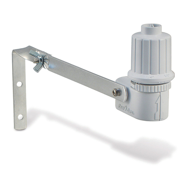
Sensor Mounting BracketAssembly
■
Mounting
Har
dwar
e
■
U
ser
’
s
M
anual
■
Quic k
R
ef
er
enc
e
Guides
■
WR 2 Quic k
R
ef
er
enc
e
Labels
■
■
1
■
3
WR2
B
enefits
•Al l
settings are
programmed
through
the
Controller
I
n
t
er
fac
e
devic
e
•Larg e
easy to
understand
icons
c
ommunica
t
e
irrigation mode and sensor
status
•
Sensor
LE D
indicator enables
one
-person
setup
,
reducing installation
time
•
Battery iseasy to install /
r
eplac
e
•
A
esthetic
appearance -no external
antennas
•Eas y
to install
,
self-levelling sensor
br
acket
mounts to flat surfaces or rain
gutt
ers
• “Quic k
Shut
Off
”
interrupts active
ir
r
iga
tion
cycle during a rain
ev
en
t
•
Enhanced
antenna
array provides
super
ior
signal reliabilitythat overcomes most line
of sight
obstruc
tions
Mounting
the
C
on
tr
oller
I
n
t
erfac
e
C
ho
ose
a location near
the
irrigation controller /
timer.
■
5
■
4
T
he
cable harness is
30
inches
(76.2 cm) long,
so
before mounting the
de
vic
e
,
ensure the wires easily
r
each
the irrigation c
on
tr
oller
’
s
connection
t
erminals.
•
Select a flat surface
adjac
en
t
■
to the irrigation c
on
tr
oller
.
•For
best
per
f
or
manc
e
,
the
Controller
I
n
t
er
fac
e
should
be installed at least
five
f
eet
(1.5m)
above the
g
r
ound
.
•
I
t
is
recommended
tha
t
the Controller
I
n
t
er
fac
ebe
installed away from sources of
electrical interference (such
as
tr
ansformers
,
gener
a
t
ors
,
pumps
,
fans
,
electrical meter boxes) and metal objects
t
o
maximize communication
r
ange
.
NOTE :
Tools
needed
for installation :
dril l,
drill
bit,
and
P
hilli p
’
s
head screwdriver
•Use
the mounting hardware
supplied
.
A
ttach
the Controller
I
n
t
er
fac
e
to the
w
all
.
2
WR2
Wireless Sensor
•
www.rainbird.com/WR2
WR2 user manual
(637469 -01)
EN
ESMX
FRCA.indd 2 8/17/2017
3:44:19
AM

!
!
!
RED
or
!
!
Wiring
the
C
on
tr
oller
I
n
t
erfac
e
to
the
I
rriga
tion
C
on
tr
oller
C
on
tr
ollers
with no sensor inputs
(with
or without pump start / master
v
alv
e)
C
OMMON
FROM
V A L VES
This
unit is
designed
to
b
e
installed in conjunction
with
24VAC
circuits only. Do
not
use with 110 or
220/230
V
A
C
cir
cuits.
T
he
C
on
tr
oller
I
n
t
er
fac
e
has
4
wires that must be c
onnect
ed
to the irrigation controller
/
timer.
If
your timer does
not
have an internal
24VAC
p
o
w
er
source, you will need to
splic
e
the red and black
C
on
tr
oller
I
n
t
er
fac
e
wires to a
24VAC
transformer (example:
R
ain
Bird
part number
63747301S).
C
on
tr
ollers
with sensor inputs (with or
without pump start / master
v
alv
e)
T O V A L VES
BL A CK WHITE GREEN
1. Disconnect power to the
ir
r
iga
tion
c
on
tr
oller
.
2. Connect the red and black wires
t
o
the
24volt
AC
power on the
ir
r
iga
tion
c
on
tr
oller
.
3. Disconnect the wires from the
C
ommon
terminal on the
c
on
tr
oller
.
4. Connect the green wireto
these
disconnected
wires using a wire
c
onnec
t
or
.
5. Connect the white wire to the
C
ommon
terminal on the
c
on
tr
oller
.
6.
R
ec
onnec
t
power to the irrigation
c
on
tr
oller
.
Ensurethe sensor switch
on
the irrigation controller
panel
is in the active
position.
ES P-MC
and
ES P -LXME
Modular
C
on
tr
ollers
RED
or
BL A
CK
GREEN
or
WHITE
BL A
CK
GREEN
WHITE
RED
T O V A L VES
1. Disconnect power to the
ir
r
iga
tion
c
on
tr
oller
.
2. Connect the red and black wires to the 24
volt
AC
power on the irrigation c
on
tr
oller
.
3.
If
pr
esen
t
,
remove “jumper
wir
e
”
bet
w
een
sensor
t
er
minals
.
4. Connect the white and green wires to
the
sensor
inputs
.
5.
R
econnec
t
power to the
ir
r
iga
tion
c
on
tr
oller
.
Ensurethe sensor switch
on
the irrigation controller
panel
is in the active
position.
1. Disconnect power to the
ir
r
iga
tion
c
on
tr
oller
.
2. Connect the red wire to the 24 volt
A
C
terminal on the irrigation
c
on
tr
oller
.
3. Connect the green and white wires to
the
sensor
t
er
minals
.
4. Connect the black wire to the
C
ommon
terminal on the
c
on
tr
oller
.
5.
R
ec
onnec
t
power to the irrigation
c
on
tr
oller
.
Ensurethe sensor switch
on
the irrigation controller
panel
is in the active
position.
WR2
Wireless Sensor
•
www.rainbird.com/WR2
3
WR2 user manual
(637469 -01)
EN
ESMX
FRCA.indd 3 8/17/2017
3:44:19
AM

I
nitial
Power Up
After
power is
applied
,
the Controller
I
n
t
er
fac
e
displays the following
ic
ons
.
C
on
tr
oller
I
n
t
erfac
e
Display
I
c
ons
Sensor
S
tatus
Battery
Lif
e
Remaining:
Four
(4)
dark
bars
indica
t
e
full
ba
tt
er
y
strength.
R
eplac
eba
tt
er
y
when only one
(1)
bar
r
emains
.
Signal
S
tr
ength:
I
llustr
a
t
es strength
of
the radio signal
bet
w
een
Sensor and
C
on
tr
oller
I
n
t
er
fac
e
.
Four
(4)
dar
k
bars indicate
maximum
signal
str
ength.
Sensor
I
ndica
t
or
/
Pairing Status: The
Sensor and
C
on
tr
oller
I
n
t
er
fac
e
synchroniz
e
c
ommunica
tion
addr
esses
.
Battery
Li f
e
and Signal Strength will
flash while synchronizing
,
and then stop
when
pair
ed
.
Environmental
C
onditions
Rainfall
Set
P
oin
t:
Select from
six (6)
set
points
ranging from 1/8”(3mm)
t
o
1/2”(13mm).
A
set point closer
to the top of the icon allows
for more precipitation to
oc
cur
before irrigation is
suspended
.
Rainfall
I
ndica
t
or
:
I
llustr
a
t
es
approximate
amoun
t
of
rainfall
relative to
Rainfall
S
et
P
oin
t
.
Rainfall Trip
I
ndica
t
or
:
Displays
when the Sensor
has
suspended
irrigation due
t
o
“Quick
Shut
O
ff
“
or
sa
tisfying
rainfall
set
poin
t
.
T
emp
er
a
tur
e
Set
P
oin
t
(Rain/Freeze Sensor only):
Select from three
(3)
set
poin
ts:
33° F (0.5° C), 37° F (3° C),
or 41°F
(5° C).
Selecting a lower
set
point allows irrigation at low
er
t
emperatures
.
T
emp
er
a
tur
e
I
ndica
t
or
(Rain/Freeze Sensor only):
I
llustr
a
t
es appro
xima
t
e
temperature
relative
t
o
T
emperatur
e
Set
P
oin
t
.
T
emp
er
a
tur
e
Trip
I
ndica
t
or
(Rain/Freeze Sensor only):
Only
displays when the
S
ensor
has
suspended
irrigation
due
totemperature
reading
tha
t
isbelow the
temperature
set
poin
t
.
4
WR2
Wireless Sensor
•
www.rainbird.com/WR2
WR2 user manual
(637469 -01)
EN
ESMX
FRCA.indd 4 8/17/2017
3:44:19
AM

I
rriga
tion
M
o
des
Programmed
I
rriga
tion:
WR 2
Wireless
Sensor is
ac
tively
manag
ing
the
ir
r
iga
tion
controller /
timer
.
Once a set point is
sa
tisfied
by
environmental
c
onditions
,
or the
“
Q
uick
Shut
Off
”
feature is
ac
tiv
a
t
ed
,
irrigation is
suspended
.
An
X
and
correspondingtr
ip
indicator
(rainfall,
t
emperatur
e
,
or
both)
will
automatically display when irrigation is
suspended
.
Suspend
I
rriga
tion
for 72 Hours:
Userhas elected
t
o
temporarily
suspend
irrigation for 72
hours
.
System will
automatically
r
esume
programmed
ir
r
iga
tion
mode after 72 hours (Note:
X
and
tr
ip
indicator
will
be displayed when returning
t
o
programmed
irrigation mode
if
set points
ar
e
satisfied).
Synchronize
the
Sensor
and
C
on
tr
oller
I
n
t
erfac
e
Afterthe
C
on
tr
oller
I
n
t
erfac
e
is wired
t
o
the irrigation timer, the Sensor
and
C
on
tr
oller
I
n
t
erfac
e
need to establish
a
radio
communication
link.When the link
is
established,
the Sensor and
C
on
tr
oller
I
n
t
erfac
e
are
considered
“
pair
ed
.
”
1. On the
C
on
tr
oller
I
n
t
er
fac
e
,
push
and
hold both
ar
r
o
w
buttons
simultaneously
to begin the installa
tion
sequenc
e
.
2.
After
the “Sensor
I
ndica
t
or
/ Pairing
S
ta
tus
”
icon flashes
,
remove the label from
the
bottom
of the
sensor
.
3.
T
he
flashing“Sensor
I
ndica
t
or / Pairing
S
ta
tus
”
icon prompts you to insert
the
ba
tt
er
y
cassette with battery into the
S
ensor
lowercasing as shown.
Align
the ar
r
o
w
on the battery cassette with the unlocked
indicator on the bottom ofthe
S
ensor
.
Override Sensor for 72 Hours:
Userhas
elec
t
ed
to
per
mit
irrigation in
ac
c
or
danc
e
with the timer schedule regardless of
environmental
conditions
(i.e.
rainfall
L
owe
r
C
asing
Battery
C
assete
and
CR203 2
ba
tt
er
y
Unlocked
Position
or low
temperature
is
detected
by
the
sensor). System
will
automatically
r
esume
programmed
irrigation mode after 72
hours
(Note:
X
and trip indicator
will
be displa
y
ed
when returning to
programmed
ir
r
iga
tion
mode
if
set points are satisfied).
4.
R
ota
t
e
the battery cassette
clock
wise
un
til
the arrow points toward the locked
indica
t
or
. T
he
light on the
bottom
of
the
Sensor
will
blink once to indicate that
the
sensor isnow powered
up
.
L
ock
ed
P
osition
LE D
flashes when
cassette
is
locked blink
WR2
Wireless Sensor
•
www.rainbird.com/WR2
5
WR2 user manual
(637469 -01)
EN
ESMX
FRCA.indd 5 8/17/2017
3:44:19
AM

5.
T
he
Sensor is successfully paired
t
o
the
Controller
I
n
t
er
fac
e
when
the
“Sensor
I
ndica
t
or
/ Pairing
S
ta
tus
”
ic
on
stops flashing
.
Once pair
ed
,
sensor
signal
strength
and battery
life
ar
e
communicated
via the Controller
I
n
t
er
fac
e
ic
ons
.
Additionally,
a blinking light
on
the
bottom
of the Sensor indicates sig
nal
strength
for 20 minutes
immedia
t
ely
following successful pair
ing
. T
hese
“
self
t
est
”
features are an indication that
y
our
WR 2 Wireles s
Sensor is
opera
tional
.
Programming
the
Set
P
oin
ts
T
he
WR 2 Wireles s
Sensor allows the c
on
tr
ac
t
or
to establish
rainfall
and
temperature
set
points
appropriate
for local
en
vir
onmen
tal
and soilc
onditions
.
A
lt
er
na
t
ely
,
the c
on
tr
ac
t
or
may elect to use the “Standard
S
etting
”:
temperature
37° F (3° C),
rain
fall ¼”
(6mm)
and
“
pr
og
r
ammed
ir
r
iga
tion
”
mode
. T
he
”
S
tandar
d
S
etting
”
is
programmed
at the factory and is
active after successful pair
ing
.
Rainfall
Set
P
oin
t
1. Push left or right
ar
r
o
w
on keypad to naviga
t
e
to the
Rainfall
I
ndica
t
or
ic
on.
2. When the
R
ainfall
I
ndica
t
or
icon flashes
,
press the +/–
butt
on
on the keypad to
set
programming details
.
Eachpress of
the
button
adjusts the
set
poin
t
.
Select from six
(6)
set points
r
ang
ing
from 1/8”(3mm)
t
o
1/2”(13mm).
3. Press the left or
r
igh
t
arrow to
ac
c
ept
programming details
and to navigate
t
o
next
ic
on.
T
emp
er
a
tur
e
Set Point (Rain/
Freeze Sensor
only)
1. Push left or right
ar
r
o
w
on keypad to
na
viga
t
e
to the
T
emperatur
e
I
ndica
t
or
ic
on.
2. When the
T
emperatur
e
I
ndica
t
or
icon flashes
,
press the +/–
butt
on
on the keypad to
set
programming details
.
Select one of
thr
ee
temperature
settings:
33°F (0.5° C), 37°F
(3° C
),
or
41°F
(5°C).
3. Press the left or
r
igh
t
arrow to
ac
c
ept
programming details
and to navigate
t
o
next
ic
on.
P
r
o
gr
amming
I
rriga
tion
M
o
des
1. Push left or right
ar
r
o
w
on keypad to
na
viga
t
e
to the
I
rr
iga
tion
M
ode
ic
on.
2. When the
I
rr
iga
tion
Mode icon flashes
,
pr
ess
the +/–
butt
on
on the keypad to
set
programming details
.
Manuallyset one of
three irrigation
modes
.
See
I
rr
iga
tion
M
odes
.
3. Press the left or
r
igh
t
arrow to
ac
c
ept
programming details
and to navigate
t
o
next
ic
on.
6
WR2
Wireless Sensor
•
www.rainbird.com/WR2
WR2 user manual
(637469 -01)
EN
ESMX
FRCA.indd 6 8/17/2017
3:44:20
AM

Saving,
Resetting
and Rest
oring
S
ettings
Save
C
on
tr
ac
t
or
Default
S
ettings
Once the
C
on
tr
oller
I
n
t
er
fac
e
isc
omplet
ely
pr
og
r
ammed
,
press
+
and right arrow
butt
ons
simultaneously for five
(5)
seconds to
sa
v
e
contractor default
setting
.
Al l
programmed
icons will
flash in unison one time
t
o
indicate program is
sa
v
ed
.
Reset
C
on
tr
ac
t
or
Default
S
ettings
T
he
Contractor default setting
stores
programming
details related to
rainfall
and
temperature
set
points
.
R
eset
and save
programming
details in
accordance with Section and
.
Reset
C
on
tr
ac
t
or
Default
S
ettings
If
this
programming
isinadvertently
changed
,
it issimple to
r
est
or
e
.
Press +and –
butt
ons
simultaneously for five
(5)
sec
onds
,
or until
the
screen goes
blank
.
W
hen
icons
r
eappear
,
c
on
tr
ac
t
or
default settings
ar
e
r
est
or
ed
.
Restore Standard
S
etting
Press the –and left
ar
r
o
w
buttons
simultaneously
f
or
five (5)
sec
onds
,
or
until the screen
goes
blank
,
to cancel
the
Contractor default
setting
and restore the
”
S
tandar
d
S
etting
”:
t
emperatur
e
37° F (3° C),
rain
fall
¼”
(6mm) and
“
pr
og
r
ammed
ir
r
iga
tion
”
mode
.
W
hen
icons
r
eappear
,
”
S
tandar
d
S
etting
”
is
ac
tiv
e
.
Select the
S
ensor
L
o
c
a
tion
T
he
communication
range for
the
WR 2
Wireless Sensor is 700 f
eet
(213.4
met
ers).
•A
blinking light on the
bottom
of
the
Sensor indicates signal
strength
for 20
minutes immediately following successful
pair
ing
. T
he
Sensor
updates
its sig
nal
strength
every 3 seconds
(i.e.
1 blink
=
reliable signal strength, series of 4 blinks
=
strongest
signal strength).
If
the sig
nal
strength
isnot optimum in one location,
try another location.
E
v
en
as little as a
f
ew
feet difference in
placement
can
impr
o
v
e
signal
str
ength.
Signal
Sensor LED
GOOD
I
nstall
1-4 Blinks
POOR
DO NOT
install
Does not blink
•
Select a
mounting
location where the
r
ain
sensor
will
receive direct
rainfall.
M
ake
sur
e
the sensor extends beyond the
r
oof
line,
tree limbs and any other
obstruc
tions
.
I
nstall the
Rain
Sensor in an area
tha
t
receives as much rain and sunlight as
the
landscape
.
Be
sure to mount the
sensor
above spray from the
spr
ink
lers
.
WR2
Wireless Sensor
•
www.rainbird.com/WR2
7
WR2 user manual
(637469 -01)
EN
ESMX
FRCA.indd 7 8/17/2017
3:44:20
AM

Sensor
M
ounting
I
nstruc
tions
This
section provides detailed ins-
tructions on how to install the
sensor
.
Sensor Bracket
A
ssembly
C
omp
onen
ts:
I
nstalling
the Sensor in
the
attachment
br
ack
et
.
To
insert the Sensor in the
attachment
br
acket
you must firstremove the Sensor
cap
.
Hold
the sensor body in one hand; gently
t
wist
the
cap with your other
hand
.
Slidethe
neck
of the sensor up through the opening of
the
extension arm.
R
einstall the
cap
.
A
clicking
sound indicates that the two latches on
the
sensor body have
full y
re-engaged
the
cap
.
A
ttachmen
t
Br
ack
et
E x
t
ension
Arm
■
remove c
ap
■
2
inser
t
Attaching the bracket to
a
gutt
er
.
Slidethe top portion of the
a
ttachmen
t
bracket over the lip of the
gutt
er
. R
ota
t
ethe
bracket downward over the gutter as
sho
wn
in the following installation
st
eps
.
■ ■
■
3
replace c
ap
mounting
bracket
gutt
er
Attaching the bracket to
a
FlatSurface.
Use the supplied hardware to mount
the
attachment
bracket to a flat surface such as
a
wallor
f
enc
e
.
Using
Multiple
C
on
tr
oller
I
n
t
erfac
e
Units
Up to four
(4)
Controller
I
n
t
er
fac
e
units can
be
paired to one
(1)
sensor
.
1. Ensure allController
I
n
t
er
fac
e
Units
ar
e
powered
up
.
2. Synchronize the Sensor to the first
Controller
I
n
t
er
fac
e
in accordance
with
Section
.
3.
As
you approach the second
C
on
tr
oller
I
n
t
er
fac
e
,
remove the battery
cassett
e
from the
S
ensor
.
Push both arrow
butt
ons
simultaneously on the second
C
on
tr
oller
I
n
t
er
fac
e
.
Wait
5
sec
onds
. R
einser
t
the
battery into the
S
ensor
. T
he
C
on
tr
oller
8
WR2
Wireless Sensor
•
www.rainbird.com/WR2
WR2 user manual
(637469 -01)
EN
ESMX
FRCA.indd 8 8/17/2017
3:44:20
AM

I
n
t
er
fac
e
“Sensor
I
ndica
t
or
/ Pairing
S
ta
tus
”
icon stops flashing when the device is
synchronized to the
S
ensor
.
C
on
tinue
with
programming
the second
C
on
tr
oller
I
n
t
er
fac
e
.
4.
R
epea
t
step 3 to pair additional
C
on
tr
oller
I
n
t
er
fac
e
units to the
S
ensor
.
5. When multiple Controller
I
n
t
er
fac
e
units
are paired to one
sensor
,
rely on the
L
CD
screen signal
strength
indications only
.
WR2
Wireless Sensor Alerts
&
T
r
oubleshooting
T
he
unique two-way
communication technology
of the
Rain Bird Wireless Rain
and
R
ain/F
r
eez
e
Sensor provides
continuous
monitoring of the Sensor status and
communicates
the
f
ollo
wing
Controller
I
n
t
er
fac
e
aler
ts
.
Alert
LCD
D
isplay
Description
Resolution
I
nitial
P
o
w
er
Up Failure
LCD
screen is blank
I
nitial Power up scr
een
/ icons do not
appear
indicating the
C
on
tr
oller
I
n
t
er
fac
e
is not
r
ec
eiving
po
w
er
.
Confirmcorrect wiring of the
C
on
tr
oller
I
n
t
er
fac
e
to the
I
rr
iga
tion
C
on
tr
oller
.
No
S
ensor
P
air
ed
“Sensor
I
ndica
t
or
/
Pairing
S
tatus
”
ic
on
continues to flash
During
I
nstallation:
T
he
sensor does not pair
and
is not c
ommunicating
with the
C
on
tr
oller
I
n
t
er
fac
e
.
1. Pair the sensor (see Section ).
2.
If
step 1 does not correct the
situa
tion,
then
check/replace
the
ba
tt
er
y
.
S
ensor
P
airing
Br
ok
en
“Sensor
I
ndica
t
or
/
Pairing
S
tatus
”
ic
on
does
not c
ommunica
t
e
battery
life
or signal
str
ength
After
the
WR 2
Wireless
Sensor is in
oper
a
tion:
A
sensor that does
not
communicate
battery life
/ signal
strength
to
the
Controller
I
n
t
er
fac
e
is
no
longer pair
ed
.
1.
First
check/replace
the
ba
tt
er
y
.
If
a new battery is installed
,
the
sensor
automatically reacquires the
C
on
tr
oller
I
n
t
er
fac
e
.
2.
If
you replace a sensor that is paired to
the
Controller
I
n
t
er
fac
e
,
you
wil l
have to pair
the
new sensor to the Controller
I
n
t
er
fac
e
.
L
o
w
B
a
tt
er
y
“Battery
Li f
e
R
emaining
”
ic
on
has only one
(1)
bar
illumina
t
ed
I
nitial Power Up Failure
R
eplac
e
the
ba
tt
er
y
.
1.
R
emo
v
e
battery cassette from
sensor
.
2.
R
emo
v
e
battery from
cassett
e
.
3.
I
nser
t
new battery using label on
ba
tt
er
y
cassette to properly orient
ba
tt
er
y
.
4.
I
nser
t
battery cassette into
sensor
.
5. Sensor
LE D
blinks once to indica
t
e
the sensor ispowered
up
.
Under
nor
mal
operation, battery should last for four
(4)
or
more
y
ears
.
Replacement or Spare
Par
ts
•WR 2
Battery -#651009S
•WR 2 Dis k
Assembly-#637810S
WARNING:
Chemical Burn
Hazar
d
.
Keep Batteries away from children.
This
product contains
a
lithium
button/coin
cell
ba
tt
er
y
.
If
a new or used lithium
button/coin
battery is swallowed
or
enters the
body
,
it can cause severe internal burns and can lead to death in as little as 2
hours
.
Always
completely secure the battery c
ompartmen
t
.
If
the battery
compartment
does not close
secur
ely
,
stop using the
pr
oduc
t
,
remove the
ba
tt
er
y
,
and keep it away from children.
If
you
think
batteries might have been swallowed or placed inside any part of the
body
,
seek
immedia
t
e
medical attention.
T
he
cells shall be disposed of
pr
oper
ly
.
E
v
en
used cells may cause injur
y
.
WR2
Wireless Sensor
•
www.rainbird.com/WR2
9
WR2 user manual
(637469 -01)
EN
ESMX
FRCA.indd 9 8/17/2017
3:44:20
AM

Declaration of
C
onf
ormit
y
Application of
Council
Dir
ec
tives:
Standards
To
W
hich
Conformity
Is
D
eclar
ed:
M
anufac
tur
er
’
s Name:
M
anufac
tur
er
’
s
A
ddr
ess:
E
quipmen
t
D
escription:
E
quipmen
t
Class:
Model Numbers:
2004/10S/EC
1999/5/EC
EN55014-1:2006
EN55022:2006
EN55014 -2:
1997 +Al:2001
EN61000-4-2
EN61000-4-3
EN61000-4-8
EN
300 220-2 V2.1.2
Rain Bird
C
or
p
.
9491
R
idgeha
v
en
C
our
t
San Diego
,
CA
92123
619-674-4068
I
rr
iga
tion
C
on
tr
oller
Class B
WRS
I
the
undersig
ned
,
hereby declare that the
equipment
specified
abo
v
e
,
conforms to the above
Directive(s)
and
S
tandar
d(s).
Place:San Diego
,
Ca.
Sig
natur
e:
Full
Name:
Ryan
W
alker
Position: Controls
Manuf. Division
Dir
ec
t
or
10
WR2
Wireless Sensor
•
www.rainbird.com/WR2
WR2 user manual
(637469 -01)
EN
ESMX
FRCA.indd 10 8/17/2017
3:44:20
AM


Í
ndic
e
I
nformación
de
segurida d
.............................................. .
12
I
n
t
er
f
erencias
con otros dispositivos electrónicos
............ .
12
I
n
tr
o
ducción
................................................................ .
12
C
omp
onent
es
del sensor
WR 2
........................................ .
13
Ventajas del sensor
WR2
.......................................................... .
13
Montaje de la interfaz del programador
.......................... .
13
I
nstalación
del cableado entre la interfaz del
pr
o
gr
amador
y el programador de riego
............................................. .
14
Puesta en marcha inicial
................................................ .
15
I
c
onos
de la pantalla de la interfaz del programador
......... .
15
Estado del sensor
...................................................... .
15
Condiciones
ambientales............................................ .
15
Modos de riego
........................................................ .
16
Sincronización del sensor y la interfaz del
pr
o
gr
amador
.... .
16
Programación de los niveles
pr
eestablecidos
................... .
17
Nivel
de
lluvia
preestablecido
...................................... .
17
T
emperaturapreestablecida
(sólo en el sensor de heladas)
.
17
Programación de los modos de riego
.............................. .
17
Guardar,
restablecer y restaurar los
niveles
...................... .
18
Guardar los valores
predeterminados
por el instalador
..... .
18
R
establec
er
los valores
predeterminados
por el
instalador
. .
18
R
estaur
ar
los valores
predeterminados
por el
instalador
.... .
18
R
estaur
ar
los valores
estánda r...................................... .
18
E
lec
ción
del lugar para el montaje del sensor
................... .
18
I
nstruc
ciones
para el montaje del sensor
......................... .
19
Uso de varias unidades de interfaz del programador
........ .
19
Alertas y resolución de problemas del sensor inalámbric
o
WR 2
Wireless Sensor
..................................................... .
20
Piezas de
r
epuest
o
........................................................ .
20
Declaración de conformidad
.......................................... .
21
EN
page 1
ES
FR
page 22
WR2 user manual
(637469 -01)
EN
ESMX
FRCA.indd 11 8/17/2017
3:44:20
AM

F
!
!
!
!
I
nformación
de
seguridad
Símbolos utilizados en
est
e
manual:
E
st
e
símbolo advierte al
usua
-
riode la presencia de
“v
oltaje
peligroso”sin aislamiento
en
el interior de la carcasa
del
producto, que podría ser sufi-
ciente para presentar riesgo
de
elec
tr
o
cución.
E
st
e
símbolo advierte al
usuario de la presencia
de
instrucciones de
funcionamien
-
to o
mantenimiento(servicio
)
imp
or
tan
t
es
.
I
n
t
erfer
encias
con otr
os
dispositivos
elec
tr
ónic
os
T
odos
los transmisores de radio
trasmiten
energía a través del
aire. Esta
energía
puede
interferir con otros dispositivos elec
tr
ónic
os
que se
encuentren
en las proximidades
del
sensor inalámbrico
WR2 .
Para reducir el
r
iesgo
de interferencias elec
tr
ónicas:
•No
coloque dispositivos electrónicos sensi
-
bles
(or
denador
es
,
t
eléf
onos
,
r
adios
,
et
c
.)
en
lasproximidades de lainterfaz de control
o
del
sensor
.
•Utilice
abrazaderaae ferrita en las
c
one
-
xiones o los cables de alimentación de los
dispositivos electrónicos
af
ec
tados
.
E L
PROG RAM ADO R DE
RIEG O
/
TEMPORI ZADO R DEB E AIS LAR
-
SE MEDIANT E UN
DISYUN T
OR
O
UN INTERRUP TOR DE
APA-
GADO.
LAS PI LAS RETI R ADAS DE L
SEN
-
SO R SE DEBE N DESECHA R
DE
ACUERD O CON LA
NOR M
A
TI V
A
L
OC AL.
L
OS
C
AMBIO S O
MODIFI C
A
CIONES
QU E
NO
HA
Y
AN
SID O
APR
OB
ADOS
EXPRESAMENT E
PO R
L
A
P
ARTE
RESPONSABL E DE
L
A
C
ONFOR
-
MI D
AD
PODRÍA N ANU L
AR
L
A
A
UT
ORI Z
A
CIÓ N
AL
US UARI O
P
AR
A
UTILI Z
AR
E L
EQUIP O
.
I
n
tr
o
duc
ción
L
e
felicitamos por haber adquirido
el sensor inalámbrico
WR 2
W
ir
eless
S
ensor
.
E l
sensor de
lluvia
inalámbrico de
Rain Bird
se
ha
diseñado para sistemas de riego
r
esidencia
-
les
y
c
omer
ciales
.
Detecta
automáticamente
las
precipitaciones e interrumpe el riego
dur
an
t
e
períodos de
lluvia
o de baja temperatura, lo
que permite ahorrar agua
y
aumentar lavida
útil del sistema de
r
iego
.
La
lógica de programación permite cancelar el
riego mediante lafunción de apagado
r
ápido
o
cuando lacantidad de
lluvia
supere el nivel
preestablecido
.
De la misma manera, el
sensor
de heladas cancelará el riego cuando la
lec
tura
de
temperatura
del sensor se encuentre
por
debajo del nivel
preestablecido
.
E l
objetivo de
Rain Bird
es desarrollar
produc
t
os
y
tecnologías que utilicen el agua de la
manera
más eficiente posible
.
L
os
sensores de
lluvia
y
de heladas son un ejemplo del compromiso
de
Rain Bird
con este uso inteligente del
agua.
Este
producto forma parte de lagama
de
soluciones de ahorro de agua de
Rain Bird,
que
incluyen el sensor de humedad del
t
er
r
eno
,
las
boquillas giratorias
y
de laserie
U,
el
ES P-SMT
y
el programador
E T
M
anager
.
Antes de instalar el sensor inalámbric
o
WR 2
Wireless Sensor, lea la
t
otalidad
de
estas
instrucciones
o c
onsult
e
la
demostración
de
pr
o
gr
amación
(www.rainbird.com/WR2). Para
conectar
correctamente
los
sensor
es
de lluvia, consulte las instr
uc
ciones
de
instalación del programador
/
temporizador de su sistema de
riego
.
12
WR2
Wireless Sensor
•
www.rainbird.com/WR2
WR2 user manual
(637469 -01)
EN
ESMX
FRCA.indd 12 8/17/2017
3:44:20
AM

!
C
omp
onent
es
del
sensor WR2
■
I
n
t
er
faz
del
pr
og
r
amador
■
S
ensor
■
Compartimento de la pila
ypilade
litio
CR2032
■
Soporte de montaje del
sensor
■
Accesorios
de
montaje
■
Manual del
usuar
io
■
Guí a
de referencia
r
ápida
■
E
tiquetas
de la guía de referencia
r
ápida
del sensor
WR2
■
Ventajas del sensor WR2
•T
odos
losajustes se programan mediante el
dispositivo de interfaz del
pr
og
r
amador
.
•
Dispone de iconos grandes
y fáciles
de
en
t
ender
para informar del modo de riego
y
el estado
del
sensor
.
•El
indicador
LE D
del sensor permite que una sola
persona realice la configuración, lo que reduce el
tiempo de instalación.
•La
pila se puede instalar ysustituir con
facilidad
.
•Su
aspecto es
est
étic
o
,
sin antenas
e
x
t
ernas
.
•La
instalación es sencilla yel soporte
aut
oniv
e
-
lante del sensor permite realizar el montaje
en
superficies planas o en canaletas de lluvia.
•El
sistema de apagado rápido interrumpe el ciclo
de riego activo cuando
lluev
e
.
•El
sistema de antena mejorado aumenta la fiabili-
dad de la señal y permite salvar la mayoría de los
obstáculos que se
encuentren
en la línea
visual
.
Montajede lain
t
er
faz
del
pr
o
gr
amador
Elija
un lugar próximo al
pr
o
gr
amador
/ temporizador de
riego
.
■
1
■
3
■
5
■
4
■■
■
La
longitud del cableado es
de
76,2 cm (30 pulgadas), por lo
que
antes de montar el
dispositivo
se
debe comprobar que los c
ables
lleguen
fácilmente a los termina-
les de conexión del
pr
o
gr
amador
de
riego
.
•Elij a
una superficie plana adyac
en
-
te alprogramador de
r
iego
.
•
Para obtener el máximo
r
endi
-
mien
t
o
,
la interfaz de control
se
debe instalar como mínimo a
una
altura de 1,5m(cincopies)
por
encima del suelo
.
•
Serecomienda instalar la
in
t
er
faz
del programador alejada
de
fuentes de interferencia eléc
tr
ica
(como
tr
ansfor
madores
,
genera
-
dores
,
bombas
,
ventiladores yca-
jasde contadores de elec
tr
icidad)
yobjetos metálic
os
,
para maximizarel alcance
de
la
c
omunicación.
•Utili ce
los accesorios de montaje suministr
ados
.
Fije
la interfaz del programador a la
par
ed
.
NOTA:
Herramientas necesarias
para
la
instalación:
taladro, broca
y
destornillado r
P
hillips
WR2
Wireless Sensor
•
www.rainbird.com/WR2
13
WR2 user manual
(637469 -01)
EN
ESMX
FRCA.indd 13 8/17/2017
3:44:20
AM

!
!
!
R O JO
o
!
!
I
nstalación
del
cableado
en
tr
e
la interfaz
del
programador y
el
programador de
riego
E
sta
unidad se ha diseñado
para
su
instalación únicamente con circui-
tos de 24
VCA.
Nose debe utilizar
con circuitosde 110 ó 220/230
V
C
A.
La
interfaz del programador
tiene
4 cables que se deben
c
onec
tar
al programador /
temp
orizador
de riego.
Si
el temporizador
no
dispone de unafuente de alimen
-
tación interna de 24
VCA,
deb
er
á
empalmarlos cables
rojo
y negr
o
de la interfaz del programadora
un transformador de 24
VCA
(por
ejemplo, el dispositivo de
Rain
Bird
con nº de
r
ef
er
encia
63747301S).
Programadores con entradas para
arranque de
bomba)
A L
AS
V Á L VUL
AS
Programadores sin entradas para
sensores (con o sin válvula principal
/
A L
AS
V Á L VUL
AS
V Á L VUL
AS
NEGRO BL AN C O VERDE
1. Desconecte laalimentación del
pr
og
r
amador
de
r
iego
.
2. Conecte loscables rojo ynegro a la
fuen
t
e
de alimentación de 24 voltios de
CA
del
programador de
r
iego
.
3. Desconecte los cables del terminal común
del
pr
og
r
amador
.
4. Conecte el cable verde a estos cables
desconectados
mediante un conector
para
cables
.
5. Conecte el cable blanco al terminal
c
omún
del
pr
og
r
amador
.
6.
V
uelv
a
a conectar laalimentación
del
C
ompr
ueb
e
que el interruptor
del
sensor del panel del
pr
o
gramador
de riego esté en posición activa.
R O JO
o
NEGRO VERDE
o
BL AN C O
Programadores
ES P-MC
y
ES P
-LXME
Modular
1. Desconecte laalimentación del
pr
og
r
amador
de
r
iego
.
2. Conecte los cables rojo ynegro a la
fuen
t
e
de alimentación de 24 voltios de
CA
del
programador
de
r
iego
.
NEGRO
VERDE
BL AN C O
R O
JO
A L
AS
V Á L VUL
AS
3.
R
etir
e
el
“
cable
puen
t
e
”
entre los
t
erminales
del sensor
(si
lo hay).
4. Conecte los cables blanco y verde a las
entradas del
sensor
.
5.
V
uelv
a
a conectar la alimentación
del
programador
de
r
iego
.
C
ompr
ueb
e
que el interruptor
del
sensor del panel del
pr
o
gramador
de riego esté en posición activa.
1. Desconecte laalimentación del
pr
og
r
amador
de
r
iego
.
2. Conecte el cable rojo alterminal de 24 voltios
de
CA
del programador de
r
iego
.
3. Conecte loscables verde yblanco a las
terminales para el
sensor
.
4. Conecte el cable negro al terminal común
del
pr
og
r
amador
.
5.
V
uelv
a
a conectar laalimentación
del
programador de
r
iego
.
C
ompr
ueb
e
que el interruptor
del
sensor del panel del
pr
o
gramador
de riego esté en posición activa.
14
WR2
Wireless Sensor
•
www.rainbird.com/WR2
WR2 user manual
(637469 -01)
EN
ESMX
FRCA.indd 14 8/17/2017
3:44:21
AM

Puesta en
mar
cha
inicial
Al
aplicar la c
or
r
ien
t
e
,
la interfaz
del
programador
muestra los iconos
siguien
t
es
.
I
c
onos
de la pantalla de
la
interfaz del
pr
o
gr
amador
E
stado
del
sensor
C
ondiciones
ambien
tales
Nivel de lluvia
pr
eestablecido:
Se puede elegir entre seis (6)
niv
eles
,
que van desde 3
mm
(1/8”)
a 13 mm
(1/2”) .
Cuanto
más
próximo esté el nivel a la
par
t
e
superior del
ic
ono
,
mayor será la
precipitación necesaria para
que
se cancele el
r
iego
.
I
ndicador
de lluvia:
I
ndica
la cantidad de lluvia
aproximada en relación al nivel
de
lluvia
preestablecido
.
I
ndicador
de cancelación
p
or
lluvia:
I
ndica
si el sensor ha
cancelado
Carga
restante de la pila:
Cuatro
(4)
barras
oscuras
indican que la pila
está
completamente
car
gada.
Sustituya la pila cuando sólo
quede una
(1)
bar
ra.
I
n
t
ensidad
de la
señal:
I
ndica
la intensidad
de
la señal de radio entre el
sensor y la interfaz
del
pr
og
r
amador
.
Cuatro (4)
barras oscuras indican
que
la intensidad de la señal
es
la máxima.
I
ndicador
del
sensor / estado
de
sincr
onización:
E l
sensor y la interfaz
del
programador
sincr
onizan
las direcciones
de
comunicación.
L
os
indicadores de carga
de
la pila e intensidad
de
la señal se
encienden
in
t
ermit
en
t
emen
t
e
durante
la sincronización y
permanecen
fijos
cuando
están sincr
onizados
.
el riego porque se ha activado la
función de
apagado
rápido o
se
ha alcanzado el nivel de lluvia
preestablecido
.
T
emp
er
a
tur
a
pr
eestablecida
(sólo en el sensor de
heladas):
Se puede elegir entre tres (3)
niveles
preestablecidos:
0,5 °C
(33
°F) ,
3
°C
(37
°F )
o 5
°C
(41
°F).
Si
se selecciona un nivel
más
bajo
,
se permitirá el riego c
on
temperaturas
más
bajas
.
I
ndicador
de temperatura
(sólo
en el sensor de
heladas):
I
ndica
la
temperatura
apr
o
ximada
en relación a la
t
emperatura
preestablecida.
I
ndicador
de cancelación
p
or
descenso
de temperatura
(sólo
en el sensor de
heladas):
Sóloaparece cuando el
sensor
ha cancelado el riego
por
que
la
lectura de
temperatura
se
encuentra
por debajo del
límit
e
preestablecido
.
WR2
Wireless Sensor
•
www.rainbird.com/WR2
15
WR2 user manual
(637469 -01)
EN
ESMX
FRCA.indd 15 8/17/2017
3:44:22
AM

Modos de
riego
R
iego
pr
o
gramado:
E l
sensor inalám
-
brico
WR 2
Wireless
Sensor gestiona
de
manera activa el
programador
/
temporizador
de
r
iego
.
C
uando
las condiciones
ambientales
alcanzan uno de los
niveles
preestablecidos
o se activa la función
de
apagado
r
ápido
,
se cancela el
r
iego
.
Cuando
se
cancela el
r
iego
,
aparecerán
aut
omá
ticamen
t
e
una
X
yel indicador de cancelación c
or
r
espon
-
diente
(lluvia ,
temperatura
o
ambos).
R
iego
cancelado durante 72 horas:
E l
usuario ha
eleg
ido
cancelar
t
empor
almen
t
e
el riego
duran
t
e
72
horas
.
D
espués
de 72
horas
,
el
sistema
r
eanudará
automáticamente
el modo de riego
pr
og
r
amado
(Nota:sise cumplen los niveles
preestablecidos
,
la
X
yel indicador de cancelación
aparecerán
al
volver al modo de riego
pr
og
r
amado
).
Ignorar las
indicaciones
del sensor dur
an
t
e
72 horas:
E l
usuario
ha
decidido
per
mitir
el riego según la
pr
og
r
amación
independientemente
de las c
ondiciones
ambientales
(incluso si el sensor
detecta
lluvia
Sincronización
del
sensor y la interfaz
del
pr
o
gr
amador
Una vez realizado el cableado entre la
interfaz del programador y el
t
emp
ori
-
zador de riego, el sensor y la interfaz
del
programador deben
establecer
un
enlac
e
de comunicación por radio.
C
uando
se
haya
establecido
el enlace, se c
onsider
ar
á
que el sensor y la interfaz del
pr
o
gr
amador
estarán
“
sincr
onizados
”
.
1. Para comenzar la
secuen
-
cia de instalación,
pulse
y
mantenga
pulsados
simultáneamente
los
dos
botones
de flecha de la
interfaz del
pr
og
r
amador
.
2. Cuando el icono
“I
ndicador
del sensor
/
Estado de sincronización
”
se encienda in
t
er
-
mit
en
t
emen
t
e
,
retire la
etiqueta
de la
par
t
e
inferior del
sensor
.
3.
El
ic
ono
“I
ndicador del sensor / Estado de sin-
cr
onización
”
se encenderá
in
t
ermit
en
t
emen
t
e
para indicarleque introduzca el
c
ompartimen
-
to de lapilacon lapilaen lacarcasa inferior
del sensor
,
como se muestra en lailustración.
Alinee
laflecha del compartimento de la
pilacon elindicador de apertura de la
par
t
e
inferior
del sensor
.
C
ar
c
asa
inf
erior
o helada). Después de 72
horas
,
el sist
ema
reanudaráautomáticamente
el modo
de
riego
programado
(Nota:sise cumplen los
C
ompartimen
t
o
de
lapila
y
pilatipo CR2032
4.
Gire
el
compartimento
de
Posición
de
apertura
niveles
preestablecidos
,
la
X
y el indicador
de
cancelación
aparecerán
al volver al modo
de
riego
pr
og
r
amado
).
la pila en el sentido de las agujas del
r
eloj
hasta el indicador de cier
r
e
.
La
luz de la
par
t
e
inferior del sensor
parpadeará
una vez
par
a
indicar que el sensor está
encendido
.
P
osición
de
cierr
e
16
WR2
Wireless Sensor
•
www.rainbird.com/WR2
El
indicador
LED
parpadea cuando el
compartimento de la
pilaestá cerrado
In
t
ermi t
en
t
e
WR2 user manual
(637469 -01)
EN
ESMX
FRCA.indd 16 8/17/2017
3:44:23
AM

5.
El
sensor estará
correctamente
sincr
onizado
con lainterfaz del programador
cuando
el icono
“I
ndicador
del sensor / Estado
de
sincr
onización
”
deje de
parpadear
.
Cuando
se
haya realizado la sincronización,la
in
t
ensidad
de laseñal ylacarga de lapila se indicar
án
mediante los iconos de la interfaz del
pr
og
r
a
-
mador
.
A
demás
,
una luzintermitente en la
parte inferiordel sensor indica la
in
t
ensidad
de
la señal durante 20 minutos después
de
realizarse
correctamente
la sincronización.
Estas
funciones de
“
aut
oc
omprobación
”
tam
-
bién indican que el sensor inalámbrico WR2
Wireless
Sensor funciona
c
or
r
ec
tamen
t
e
.
Programación de
los
niveles
pr
eestablecidos
El
sensor inalámbrico
WR 2 Wireles s
Sensor
per
mit
e
alinstalador establecer losniveles de
lluvia
y
temperatura preestablecidos
adecuados para las
condiciones locales ambientales
y
del
t
er
r
eno
.
A
lt
erna
tiv
amen
t
e
,
el instalador también
puede
elegir
utiliza r
los valores
estándar
:
t
emperatura
3
°C (37 °F) , lluvi a
6 mm
(¼” ) y
modo de
“
r
iego
pr
og
r
amado
”
.
L
os
valores estándar se
pr
og
r
aman
en fábrica
y
son los que están activos después
de
realizar
correctamente
lasincronización.
Nivel de lluvia
pr
eestablecido
1. Pulse la flecha a la
der
e
-
cha o a la izquierda
del
teclado para desplazarse
alicono del indicador
de
lluvia.
2. Cuando el icono
del
indicador de
lluvia
se
encienda
in
t
er
mit
en
t
e
-
men
t
e
,
pulse el
bot
ón
+/
–
del teclado
para
ajustar la
pr
og
r
amación.
Cada pulsación
del
botón permite ajustar
el nivel
preestablecido
.
Sepuede elegir
en
tr
e
seis
(6)
niv
eles
,
que
v
an
desde 3 mm
(1/8”)
a 13
mm (1/2”).
3.
Pulse la flecha
a
la
der
e
-
cha o
la flecha
a
la
izquier-
da para aceptar
los
ajustes
de
la
programación y
pasar
al
iconosiguien
t
e
.
T
emp
er
a
tur
a
pr
eestablecida
(sólo en el sensor de
heladas)
1. Pulse la flecha a la
der
e
-
cha o a laizquierda
del
teclado para desplazarse
alicono del indicador
de
t
emperatur
a.
2. Cuando el icono del
indicador de
t
emperatura
se encienda
in
t
ermit
en
-
t
emen
t
e
,
pulse el
bot
ón
+/
–
del teclado
para
ajustar la
prog
r
amación.
Seleccioneuno de los
tres
ajustes de
t
emperatura
posibles : 0,5
°C (3 3 °F) ,
3
°C (37 °F )
o 5
°C (41
°F).
3. Pulse la flecha a la
derecha o la flechaa la
izquierda para ac
eptar
los ajustes de la
pr
og
r
a
-
mación
y
pasar al
ic
ono
siguien
t
e
.
Programación de
los
modos de
riego
1. Pulse la flecha a la
der
e
-
cha o a la izquierda
del
teclado para
desplazar-
se al icono del modo
de
r
iego
.
2. Cuando el icono
del
modo de riego
se
encienda in
t
ermit
en
t
e
-
men
t
e
,
pulse el
bot
ón
+/–del teclado
par
a
ajustar la
pr
og
r
amación.
Establezca
manual
-
mente uno de los
tres
modos de riego
posi
-
bles
.
Consulte la
sec
ción
Modos de
r
iego
.
3. Pulse la flecha a la
derecha o la flecha a la
izquierda para
ac
eptar
los ajustes de la
pr
og
r
a
-
mación ypasar al
ic
ono
siguien
t
e
.
WR2
Wireless Sensor
•
www.rainbird.com/WR2
17
WR2 user manual
(637469 -01)
EN
ESMX
FRCA.indd 17 8/17/2017
3:44:23
AM
Other manuals for WR2
2
Table of contents
Languages:
Other Rain Bird Accessories manuals

Rain Bird
Rain Bird WR2-48 User manual

Rain Bird
Rain Bird Sod Cup Kit User manual

Rain Bird
Rain Bird TBOS K80710 User manual

Rain Bird
Rain Bird SMRT-Y User manual

Rain Bird
Rain Bird WR2RFC-48 User manual

Rain Bird
Rain Bird WR2 User manual

Rain Bird
Rain Bird FS200B User manual

Rain Bird
Rain Bird WRFT User manual

Rain Bird
Rain Bird RSD-BEx Manual

Rain Bird
Rain Bird RSD-CEx User manual