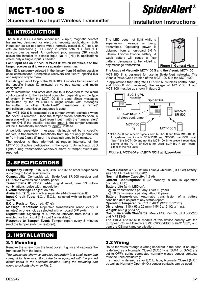
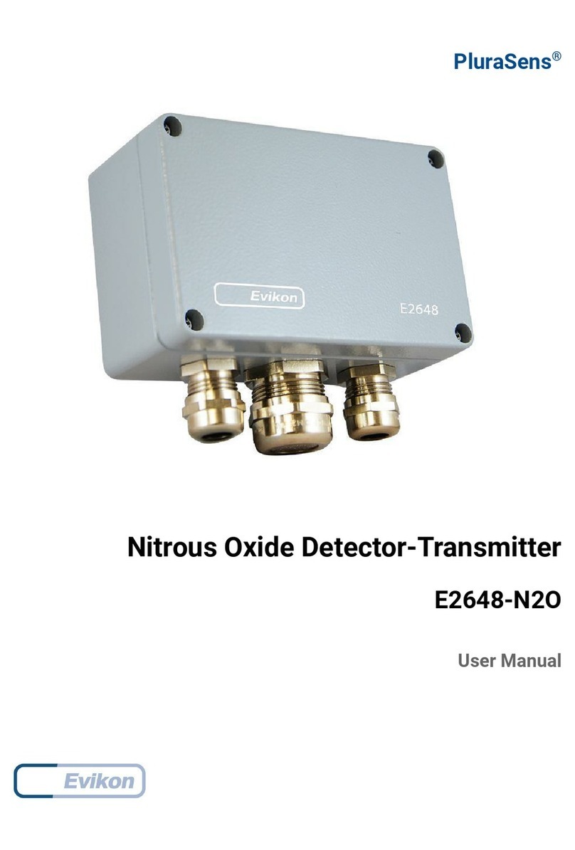
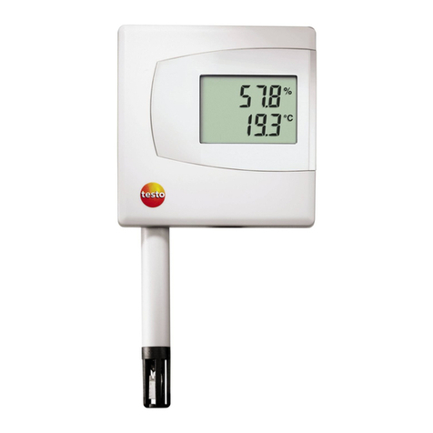
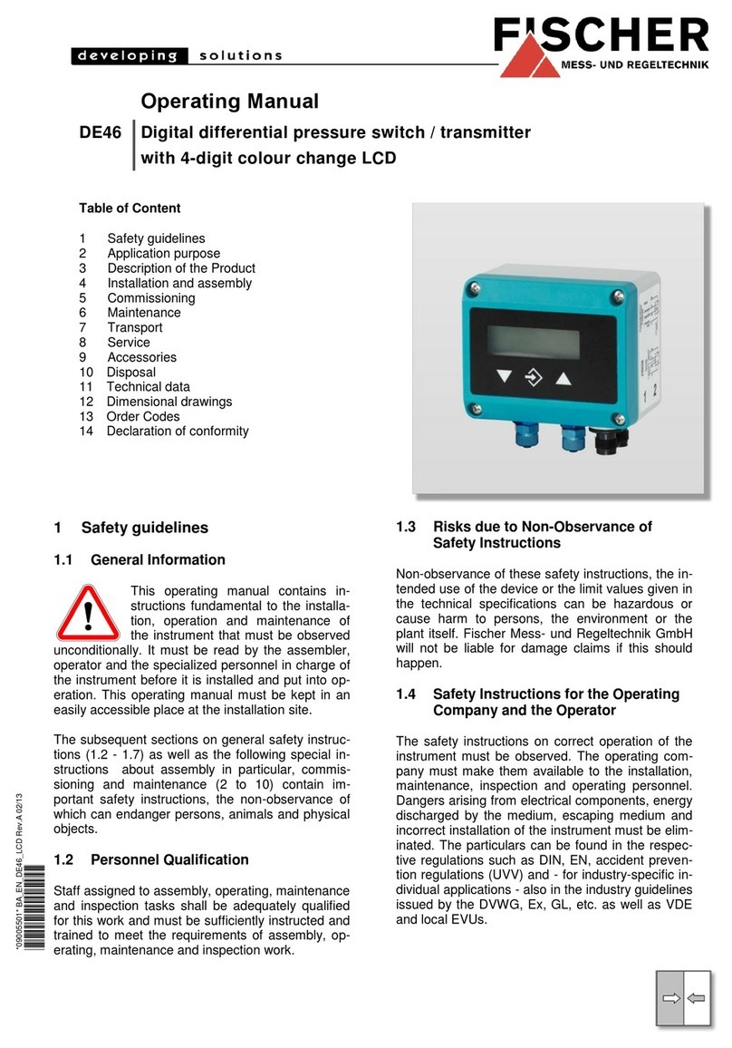
Rain Bird PT3002 Technical specifications

PT3002 Flow SensorTransmitter
Installation and Programming Instructions
Instrucciones de instalación y programación

2PT3002 Flow SensorTransmitter • Installation and Programming Instructions
ENG
ENG
Contents
Wiring Instructions............................................3
For Use As A High Flow Shut O Device With A
Stand Alone Controller......................................4
Using a Normally Closed Master Valve .................4
Using a Normally Open Master Valve ..................4
For Output to Maxicom®....................................5
Initial Powerup ................................................6
Display and Key Pad. . . . . . . . . . . . . . . . . . . . . . . . . . . . . . . . . . . . . . . . . . .6
General Programming ........................................6
Step 1 .......................................................6
Step 2a......................................................9
Step 2b.....................................................11
Resetting the 3002 After a High Flow Occurrence..........13
Resetting the 3002To ZeroTotal Flow Readings ...........13
Appendix A .....................................................
Appendix B .....................................................
ESP
page 14

PT3002 Flow SensorTransmitter • Installation and Programming Instructions 3
Wiring Instructions
NOTE: Refer to the PT3002 Flow Monitor and NEMACAB Installation sheet for more detailed instructions.
Wire red wire from ow sensor to terminal four on
terminal block with seven terminals. Wire black wire from
ow sensor to terminal ve on terminal block with seven
terminals. See wiring diagram label on side of PT3002.
Wire the red lead (+) from the PT Power Supply to the
terrminal one on the three port terminal block. Wire the
black / white (-) wire to terminal two of the three port
terminal block.
Flow
Sensor
PT3002
red
1
2
3
4
5
6
7
1
2
3
4
5
1
2
3
black
blue
red
black
blue/white
PT3002
1
2
3
4
5
6
7
1
2
3
4
5
1
2
3
Controller
Master
Valve
COM
COM MV
PT3002
1
2
3
4
5
6
7
1
2
3
4
5
1
2
3
24 Volt
Power Supply
Master
Valve
COM
COM LINE
PT3002
1
2
3
4
5
6
7
1
2
3
4
5
1
2
3
Link MIB Board
or
Site Satellite
SENSOR PORT
(-)(+)
PT3002
1
2
3
4
5
6
7
1
2
3
4
5
1
2
3
PT3002
1
2
3
4
5
6
7
1
2
3
4
5
1
2
3
Pulse Decoder
PT
Power
Supply
(-) (+)

4PT3002 Flow SensorTransmitter • Installation and Programming Instructions
Wiring Instructions (cont.)
Using a Normally Closed MasterValve
Wire one leg of the master valve solenoid wire to the
Relay 1 NC 2 terminal. Wire the Relay 1 COM 3 terminal to
the master valve terminal in the controller.
Note: Wire master valve common to controller common
as in any normal installation.
Flow
Sensor
PT3002
red
1
2
3
4
5
6
7
1
2
3
4
5
1
2
3
black
blue
red
black
blue/white
PT3002
1
2
3
4
5
6
7
1
2
3
4
5
1
2
3
Controller
Master
Valve
COM
COM MV
PT3002
1
2
3
4
5
6
7
1
2
3
4
5
1
2
3
24 Volt
Power Supply
Master
Valve
COM
COM LINE
PT3002
1
2
3
4
5
6
7
1
2
3
4
5
1
2
3
Link MIB Board
or
Site Satellite
SENSOR PORT
(-)(+)
PT3002
1
2
3
4
5
6
7
1
2
3
4
5
1
2
3
PT3002
1
2
3
4
5
6
7
1
2
3
4
5
1
2
3
Pulse Decoder
PT
Power
Supply
(-) (+)
For Use As A High Flow Shut O Device With A Stand Alone Controller
Using a Normally Open MasterValve
Wire one leg of the master valve solenoid wire to the Relay
1 NO 1 terminal. Wire the second leg of the solenoid to an
auxiliary 24 volt power supply. Wire the Relay 1 COM 3 to
the other leg of the auxiliary power supply. When a high
ow condition occurs the internal relay closes, powering
the normally open master valve and closing it.
Flow
Sensor
PT3002
red
1
2
3
4
5
6
7
1
2
3
4
5
1
2
3
black
blue
red
black
blue/white
PT3002
1
2
3
4
5
6
7
1
2
3
4
5
1
2
3
Controller
Master
Valve
COM
COM MV
PT3002
1
2
3
4
5
6
7
1
2
3
4
5
1
2
3
24 Volt
Power Supply
Master
Valve
COM
COM LINE
PT3002
1
2
3
4
5
6
7
1
2
3
4
5
1
2
3
Link MIB Board
or
Site Satellite
SENSOR PORT
(-)(+)
PT3002
1
2
3
4
5
6
7
1
2
3
4
5
1
2
3
PT3002
1
2
3
4
5
6
7
1
2
3
4
5
1
2
3
Pulse Decoder
PT
Power
Supply
(-) (+)

PT3002 Flow SensorTransmitter • Installation and Programming Instructions 5
Wire the Pulse 1 Out terminal four to the positive (+)
terminal of the sensor port on a link MIB board or Site
Satellite. Wire Pulse 2 Out terminal ve to the negative
(–) terminal of the sensor port on a link MIB board or Site
Satellite.
Wire the Pulse 1 Out terminal four to the blue wire of a
pulse decoder if using two wire communications between
CCU and satellite Controller. Wire Pulse 2 Out terminal ve
to the blue / white wire of a pulse decoder.
Flow
Sensor
PT3002
red
1
2
3
4
5
6
7
1
2
3
4
5
1
2
3
black
blue
red
black
blue/white
PT3002
1
2
3
4
5
6
7
1
2
3
4
5
1
2
3
Controller
Master
Valve
COM
COM MV
PT3002
1
2
3
4
5
6
7
1
2
3
4
5
1
2
3
24 Volt
Power Supply
Master
Valve
COM
COM LINE
PT3002
1
2
3
4
5
6
7
1
2
3
4
5
1
2
3
Link MIB Board
or
Site Satellite
SENSOR PORT
(-)(+)
PT3002
1
2
3
4
5
6
7
1
2
3
4
5
1
2
3
PT3002
1
2
3
4
5
6
7
1
2
3
4
5
1
2
3
Pulse Decoder
PT
Power
Supply
(-) (+)
For Output to Maxicom® or Site Control
(complete step
1
on pages 6 to 8 and step
2b
on pages 11 to 12)

6PT3002 Flow SensorTransmitter • Installation and Programming Instructions
General Programming
Step 1
3. At the Setup
menu, press u to
go to the Flow 1
Setup Screen.
4. Press p to go to
the Flow 1 Rate
Screen.
1. Press MENU
to enter
Programming
Mode. Press
q to go to the
Password Screen.
2. Use the arrow
keys to enter a 4
digit password
then press ENTER
OR press ENTER
to bypass using a
password.
When the PT3002 is rst powered up, it runs through
internal self checks, while displaying “PT3002 DIC
Initializing." At the end of this cycle its normal display
will appear.
Plug the PT3002 Flow Monitor
power supply into a 120 VAC
electrical outlet.
Menu Enter
TX RX
Relay 1 Pulse Out
Model 3002
Menu
Enter
1-Switch to main menu
2-Backward/Previous menu
1-Save value
2-Forward/Next menu
1-Select Menu option
2-Increase numerical value
1-Select Menu option
2-Decrease numerical value
1-Select Menu option
2-Move cursor to the right
Display and Key Pad
Initial Powerup
Rain Bird
PTPWRSUPP
Menu Enter
RESET SETUP DIAG
Menu Enter
0000
Enter password
Menu Enter
Menu Enter
PWORD DSPY FLOW1
RATE TOTAL SENSR
SETUP
Flow 1 Setup
5. Press pto Set
Units.
Menu Enter
UNITS #.DIG CUST
Flow 1 rate

PT3002 Flow SensorTransmitter • Installation and Programming Instructions 7
7. Press MENU once
to go to the Flow
1 Setup Screen.
11. Press MENU twice
to go to the Flow
1 Setup Screen.
8. Press q to Set
TOTAL.
12. Press u to Set
SENSOR.
9. Press p to Set
UNITS.
13. Press p to Set
TYPE.
10. Set UNITS for gal
by using p or q
then press ENTER
(the PT3002 saves
the setting)
14. Press p or q
until "Pulse –DI"
appears, then
press ENTER. The
PT3002 saves the
setting and brings
you back to the
screen below
15. Press u to Set
DICAL.
6. Set UNITS for
GPM* by using p
or q then press
ENTER (the PT3002
saves the setting).
(Note: GPM used
as an example
throughout this
manual.)
Menu Enter
Menu Enter
Menu Enter
GPM
GPM
UNITS #.DIG CUST
Flow 1 rate
Flow 1 rate
Flow 1 total
Menu Enter
Menu Enter
UNITS #.DIG CUST
Pulse–DI
Flow 1 total
Sensor 1 type
Menu Enter
gal
Total 1 units
Menu Enter
Menu Enter
Menu Enter
Menu Enter
RATE TOTAL SENSR
RATE TOTAL SENSR
TYPE AVG DICAL
TYPE AVG DICAL
Flow 1 Setup
Flow 1 Setup
Flow 1 sensor
Flow 1 sensor

8PT3002 Flow SensorTransmitter • Installation and Programming Instructions
Follow Step
2a
or Step
2b
to complete setup.
16. Press p to
Set SENSOR K
FACTOR.
20. Press MENU until
you arrive at
the GPM / Total
Screen.
21. The screen will
look as to the
right.
17. Use the pqu
keys to enter the K
FACTOR then press
ENTER (the PT3002
saves the setting
and returns to the
Sensor Calibration
Screen)
18. Press q to Set
SENSOR OFFSET.
Note: See instructions pages 26 - 29 for Rain Bird Flow
Sensor K & Oset information or instruction sheet
included with Rain Bird Flow Sensors.
Note: See instructions pages 26 - 29 for Rain Bird Flow
Sensor K & Oset information or instruction sheet
included with Rain Bird Flow Sensors.
19. Use the pqu
keys to enter the
OFFSET then press
ENTER (the PT3002
saves the setting
and returns to the
Sensor Calibration
Screen)
Menu Enter Menu Enter
Menu Enter
Menu Enter
Menu Enter
Menu Enter
KNUM OFFSET KNUM OFFSET
0.0 gal
KNUM OFFSET
1.00000000
+0.00000001
DI Sensor Cal. DI Sensor Cal.
0.00 GPM
DI Sensor Cal.
DI Sensor K Num
DI Sensor Oset
Step 1cont.

PT3002 Flow SensorTransmitter • Installation and Programming Instructions 9
Step
2a
Set Up as a High Flow Shut O Device
With a Stand Alone Controller
Be Sure Unit is Set Up Through Step 1
Above Before Continuing
3. At the Setup
screen, press
ENTER.
5. Press p for
FUNC.
8. Press ENTER.
9. Press p.
6. Press p for
MANUAL.
7. Press p or q
until ALARM
appears. Press
ENTER to SAVE.
4. Press p for RLY1.
1. Press MENU
to enter
Programming
Mode. Press
q to go to the
Password Screen.
2. Use the arrow
keys to enter a 4
digit password
then press ENTER
OR press ENTER
to bypass using a
password.
Menu Enter
RESET SETUP DIAG
Menu Enter
0000
Enter password
Menu Enter
Menu Enter
Menu Enter
Menu Enter
Menu Enter
Menu Enter
Menu Enter
PWORD DSPY FLOW1
FUNC MANUAL
FUNC INPUT UNITS
LATCH SETPT RELP
Manual Control
Alarm
RLY1 PULSE AOUT1
SETUP
Relay 1
Relay 1
Relay 1
Relay 1 function
Relay 1 function
SETUP

10 PT3002 Flow Sensor Transmitter • Installation and Programming Instructions
10. Press p or q
until brackets are
around "ON" then
press ENTER.
14. Press p.
11. Press q for SET
POINT.
13. Press ENTER.
12. Use the pqu
keys to set the
Flow Threshold
Amount. (This
amount, once
exceeded, will
cause the PT3002
to break the
common and
close the master
valve, stopping
ow.) Press ENTER
when done.
15. Use the pqu
keys to set the
number of desired
seconds for the
PT3002 to wait
before breaking
the valve common
and closing the
Master Valve
once a High Flow
occurs. Press
ENTER to SAVE.
Menu Enter Menu Enter
Menu Enter
Menu Enter
Menu Enter
Menu Enter
Menu Enter
(ON) OFF SDLY
SDLY
LATCH SETPT RELP
LATCH SETPT RELP
Relay 1 latch Relay 1
Relay 1
Relay 1
Relay 1
+1.00000000
+0.00000000 s
Set Point
Trigger delay
16. Press MENU until
you arrive at
the GPM / Total
Screen.
17. The screen will
look as to the
right.
Menu Enter
0.0 gal
0.00 GPM
Step
2a
cont.

PT3002 Flow SensorTransmitter • Installation and Programming Instructions 11
Step
2b
Set Up For Use With Central Control
Be Sure Unit is Set Up Through Step 1
Above Before Continuing
3. At the Setup
screen, press
ENTER.
5. Press p for
FUNC.
8. Press p or q until
"gal" is displayed.
Press ENTER to
SAVE, then press
ENTER again.
9. Press p to SET
RATE.
6. Press p or q
until "TOTALIZER"
is displayed and
then press ENTER.
7. Press u to set
PULSE RATE
UNITS.
4. Press p for RLY1.
1. Press MENU
to enter
Programming
Mode. Press
q to go to the
Password Screen.
2. Use the arrow
keys to enter a 4
digit password
then press ENTER
OR press ENTER
to bypass using a
password.
Menu Enter
RESET SETUP DIAG
Menu Enter
0000
Enter password
Menu Enter
Menu Enter
Menu Enter
Menu Enter
Menu Enter
Menu Enter
Menu Enter
PWORD DSPY FLOW1
FUNC MANUAL
gal
RATE CTIME
Totalizer
FUNC INPUT UNITS
RLY1 PULSE AOUT1
SETUP
Relay 1
Pulse rate units
Relay 1
Relay 1 function
Relay 1
SETUP

12 PT3002 Flow Sensor Transmitter • Installation and Programming Instructions
Step
2b
cont.
12. Use the pq
u keys to SET
CLOSETIME.
(Note: this will
normally be set
100 ms). Press
ENTER to SAVE.
13. Press MENU three
(3) times to return
to Flow Total
Screen.
10. Use the pqu
keys to SET PULSE.
(Note: this will
normally be set
to +1.00000000).
Press ENTER to
SAVE.
11. Press q to SET
CLOSETIME.
Menu Enter
Menu Enter
Menu Enter
Menu Enter
RATE CTIME
RATE CTIME
+1.00000000
0100 ms
Relay 1
Relay 1
1 PULSE = ?
Time Closed
Menu Enter
0.0 gal
0.00 GPM
14. The screen will
look as to the
right.

PT3002 Flow SensorTransmitter • Installation and Programming Instructions 13
Resetting the 3002 After a High Flow
Occurrence
3. Press p (OK) to
Reset.
1. Press MENU
to enter
Programming
Mode. Press p to
go to the Reset
Screen.
2. Press q to Reset
Relay.
Menu Enter
RESET SETUP DIAG
Menu Enter
Menu Enter
FLOW1 RLY1
FLOW1 RLY1
RESET
RESET
Menu Enter
OK CANCEL
Reset relay 1?
4. Press MENU
twice to return to
the GPM / Total
Screen.
Resetting the 3002To Zero Total Flow
Readings
3. Press p (OK) to
Reset.
1. Press MENU
to enter
Programming
Mode. Press p to
go to the Reset
Screen.
2. Press p to Reset
Flow.
Menu Enter
RESET SETUP DIAG
Menu Enter
Menu Enter
FLOW1 RLY1
FLOW1 RLY1
RESET
RESET
Menu Enter
OK CANCEL
Reset ow 1?
4. Press MENU
twice to return to
the GPM / Total
Screen.

14 PT3002 Flow Sensor Transmitter • Installation and Programming Instructions
ESP
ESP
Contenidos
Instrucciones de cableado....................................3
For Use As A High Flow Shut O Device With A
Stand Alone Controller......................................4
Using a Normally Closed Master Valve .................4
Using a Normally Open Master Valve ..................4
For Output to Maxicom®....................................5
Initial Powerup ................................................6
Display and Key Pad. . . . . . . . . . . . . . . . . . . . . . . . . . . . . . . . . . . . . . . . . . .6
General Programming ........................................6
Step 1 .......................................................6
Step 2a......................................................9
Step 2b.....................................................11
Resetting the 3002 After a High Flow Occurrence..........13
Resetting the 3002To ZeroTotal Flow Readings ...........13
Appendix A .....................................................
Appendix B .....................................................
ENG
page 2

PT3002 Flow SensorTransmitter • Installation and Programming Instructions 15
Instrucciones de cableado
NOTA: Consulte el instructivo del monitor de ujo PT3002 y NEMACAB para instrucciones más detalladas.
Conecte el cable rojo del sensor de ujo a la terminal
cuatro del bloque de siete terminales. Conecte el cable
negro del sensor de ujo a la terminal cinco del bloque
de siete terminales. Vea la etiqueta del diagrama de
cableado en el costado del PT3002
Conecte el cable rojo(+) del suministro eléctrico PT a la
terminal uno del bloque de terminales de tres puertos.
Conecte el cable negro / blanco (-) a la terminal dos del
bloque de terminales de tres puertos.
Sensor
de Flujo
PT3002
rojo
1
2
3
4
5
6
7
1
2
3
4
5
1
2
3
negro
azul
rojo
negro
azul/blanco
PT3002
1
2
3
4
5
6
7
1
2
3
4
5
1
2
3
Controlador
Válvula
maestra
COM
COM MV
PT3002
1
2
3
4
5
6
7
1
2
3
4
5
1
2
3
Suministro
eléctrico de
24 voltios
Válvula
maestra
COM
COM LÍNEA
PT3002
1
2
3
4
5
6
7
1
2
3
4
5
1
2
3
Tablero de
enlace MIB
o
Sitio de satélite
SENSOR PORT
(-)(+)
PT3002
1
2
3
4
5
6
7
1
2
3
4
5
1
2
3
PT3002
1
2
3
4
5
6
7
1
2
3
4
5
1
2
3
Decodicador
de pulso
Suministro
de energía
PT
(-) (+)

16 PT3002 Flow Sensor Transmitter • Installation and Programming Instructions
Instrucciones de cableado (cont.)
Usando una válvula maestra normalmente cerrada
Conecte uno de los cables del solenoide de la válvula a la
terminal del Relé 1 2NC. Conecte el cable de la terminal
del Relé 1 COM 3 a la terminal de la válvula maestra en el
controlador.
Nota: Conecte el cable común de la válvula maestra al
controlador como en cualquier instalación normal.
Sensor
de Flujo
PT3002
rojo
1
2
3
4
5
6
7
1
2
3
4
5
1
2
3
negro
azul
rojo
negro
azul/blanco
PT3002
1
2
3
4
5
6
7
1
2
3
4
5
1
2
3
Controlador
Válvula
maestra
COM
COM MV
PT3002
1
2
3
4
5
6
7
1
2
3
4
5
1
2
3
Suministro
eléctrico de
24 voltios
Válvula
maestra
COM
COM LÍNEA
PT3002
1
2
3
4
5
6
7
1
2
3
4
5
1
2
3
Tablero de
enlace MIB
o
Sitio de satélite
SENSOR PORT
(-)(+)
PT3002
1
2
3
4
5
6
7
1
2
3
4
5
1
2
3
PT3002
1
2
3
4
5
6
7
1
2
3
4
5
1
2
3
Decodicador
de pulso
Suministro
de energía
PT
(-) (+)
Para usar como un dispositivo de apagado de alto ujo con un controlador
independiente
Usando una válvula maestra normalmente abierta
Conecte uno de los cables del solenoide de la válvula
maestra a la terminal del relé 1 NO 1. Conecte el segundo
cable del solenoide de la válvula a una fuente auxiliar de
energía de 24 voltios. Conecte el cable del Relé 1 COM
3 al otro cable de la fuente auxiliar de energía. Cuando
ocurre una condición de alto ujo el relé interno se cierra,
activando la válvula maestra que está normalmente
abierta y cerrándola.
Sensor
de Flujo
PT3002
rojo
1
2
3
4
5
6
7
1
2
3
4
5
1
2
3
negro
azul
rojo
negro
azul/blanco
PT3002
1
2
3
4
5
6
7
1
2
3
4
5
1
2
3
Controlador
Válvula
maestra
COM
COM MV
PT3002
1
2
3
4
5
6
7
1
2
3
4
5
1
2
3
Suministro
eléctrico de
24 voltios
Válvula
maestra
COM
COM LÍNEA
PT3002
1
2
3
4
5
6
7
1
2
3
4
5
1
2
3
Tablero de
enlace MIB
o
Sitio de satélite
SENSOR PORT
(-)(+)
PT3002
1
2
3
4
5
6
7
1
2
3
4
5
1
2
3
PT3002
1
2
3
4
5
6
7
1
2
3
4
5
1
2
3
Decodicador
de pulso
Suministro
de energía
PT
(-) (+)

PT3002 Flow SensorTransmitter • Installation and Programming Instructions 17
Conecte el cable desde la salida de la terminal 4 del pulso
1 a la terminal (+) del sensor de puerto en un tablero de
enlace MIB ó a un sitio de satélite. Conecte el cable desde
la salida de la terminal 5 del pulso 2 a la terminal negativa
(-) del sensor de puerto en un tablero de enlace MIB ó a un
sitio de satélite.
Conecte el cable desde la salida de la terminal 4 del
pulso1 al cable azul de un decodicador de pulso si se
están usando dos cables de comunicación entre un CCU
y un controlador de satélite. Conecte el cable desde la
salida de la terminal 5 del pulso 2 al cable azul/blanco de
un decodicador de pulso.
Sensor
de Flujo
PT3002
rojo
1
2
3
4
5
6
7
1
2
3
4
5
1
2
3
negro
azul
rojo
negro
azul/blanco
PT3002
1
2
3
4
5
6
7
1
2
3
4
5
1
2
3
Controlador
Válvula
maestra
COM
COM MV
PT3002
1
2
3
4
5
6
7
1
2
3
4
5
1
2
3
Suministro
eléctrico de
24 voltios
Válvula
maestra
COM
COM LÍNEA
PT3002
1
2
3
4
5
6
7
1
2
3
4
5
1
2
3
Tablero de
enlace MIB
o
Sitio de satélite
SENSOR PORT
(-)(+)
PT3002
1
2
3
4
5
6
7
1
2
3
4
5
1
2
3
PT3002
1
2
3
4
5
6
7
1
2
3
4
5
1
2
3
Decodicador
de pulso
Suministro
de energía
PT
(-) (+)
Para salida hacia Maxicom® o Site Control
(complete el paso
1
de las páginas 6 a la 8 y el paso
2b
en las páginas 11 a la 12)

18 PT3002 Flow Sensor Transmitter • Installation and Programming Instructions
Programación general
Paso 1
3. En el menú de
conguración
presione u para
ir a la pantalla de
conguración del
ujo1 (Flow 1)
4. Presione p para
ir a la pantalla de
rango de ujo 1
(Flow 1).
1. Presione MENU
para ingresar a
la modalidad de
programación.
Presione qpara
ir a la pantalla de
contraseña.
2. Utilice las teclas de
echa para ingresar
una contraseña de
4 dígitos y después
presione ENTER ó
presione ENTER
para no usar la
contraseña.
Cuando el PT3002 es inicialmente encendido, se realiza
una auto vericación interna, mientras en la pantalla
aparece “PT3002 DIC Initializing." Al nal de este ciclo
la pantalla vuelve a su estado normal.
Conecte el suministro eléctrico
del monitor de ujo PT3002 a una
salida de corriente de 120 VAC.
Menu Enter
TX RX
Relay 1 Pulse Out
Model 3002
Menu
Enter
1- Cambie al menú principal
2- Atrás/ Menú previo
1-Salvar valor
2-Adelante/Siguiente menú
1-Seleccione opción de menú
2-Incremente el valor numérico
1-Seleccione opción de menú
2-Disminuya el valor numérico
1-Seleccione opción de menú
2-Mueva el cursor a la derecha
Pantalla y teclado
Encendido inicial
Rain Bird
PTPWRSUPP
Menu Enter
RESET SETUP DIAG
Menu Enter
0000
Enter password
Menu Enter
Menu Enter
PWORD DSPY FLOW1
RATE TOTAL SENSR
SETUP
Flow 1 Setup
5. Presione p para
jar unidades
(UNITS).
Menu Enter
UNITS #.DIG CUST
Flow 1 rate

PT3002 Flow SensorTransmitter • Installation and Programming Instructions 19
7. Presione MENU
una vez para ir
a la pantalla de
conguración de
ujo 1.
11. Presione MENU
dos veces para ir
a la pantalla de
conguración de
ujo 1.
8. Presione q para
jar el TOTAL.
12. Presione u para
jar SENSOR.
9. Presione p para
jar UNITS.
13. Presione p para
jar TYPE.
10. Fijar UNITS para
gal usando p
ó q y después
presione ENTER
(el PT3002 guarda
la conguración)
14. Presione p ó
q hasta que
"Pulse –DI"
aparece, después,
presione ENTER.
El PT3002 guarda
la conguración y
regresa a la pantalla
de abajo.
15. Presione u para
jar DICAL.
6. Fije las unidades
(UNITS) para
GPM* usando p
ó q y después
presione ENTER
(el PT3002 salva
la conguración).
(Nota: GPM se usa
como un ejemplo
en todo el manual.)
Menu Enter
Menu Enter
Menu Enter
GPM
GPM
UNITS #.DIG CUST
Flow 1 rate
Flow 1 rate
Flow 1 total
Menu Enter
Menu Enter
UNITS #.DIG CUST
Pulse–DI
Flow 1 total
Sensor 1 type
Menu Enter
gal
Total 1 units
Menu Enter
Menu Enter
Menu Enter
Menu Enter
RATE TOTAL SENSR
RATE TOTAL SENSR
TYPE AVG DICAL
TYPE AVG DICAL
Flow 1 Setup
Flow 1 Setup
Flow 1 sensor
Flow 1 sensor

20 PT3002 Flow Sensor Transmitter • Installation and Programming Instructions
Siga los pasos
2a
ó
2b
para
completar la conguración.
16. Presione p para
jar el FACTOR K
del SENSOR.
20. Presione MENU
hasta llegar a la
pantalla GPM /
Total.
21. La pantalla se
verá como a la
derecha.
17. Utilice las teclas
pqu para
ingresar el FACTOR
K y después
presione ENTER (el
PT32002 guarda
la conguración y
regresa a la pantalla
de calibración del
sensor)
18. Presione q para
jar SENSOR
OFFSET.
Nota: Vea las instrucciones en las paginas 26 - 29 para
información sobre el sensor K de ujo marca Rain Bird y la
hoja de instrucciones ó información impresa incluida con
los sensores de ujo Rain Bird.
Nota: Vea las instrucciones en las paginas 26 - 29 para
información sobre el sensor K de ujo marca Rain Bird y la
hoja de instrucciones ó información impresa incluida con
los sensores de ujo Rain Bird.
19. Utilice las teclas
pqu para ingresar
el OFFSET y después
presione ENTER (el
PT32002 guarda
la conguración y
regresa a la pantalla de
calibración del sensor)
Menu Enter Menu Enter
Menu Enter
Menu Enter
Menu Enter
Menu Enter
KNUM OFFSET KNUM OFFSET
0.0 gal
KNUM OFFSET
1.00000000
+0.00000001
DI Sensor Cal. DI Sensor Cal.
0.00 GPM
DI Sensor Cal.
DI Sensor K Num
DI Sensor Oset
Paso 1cont.
Other manuals for PT3002
1
Table of contents
Languages:
Other Rain Bird Transmitter manuals
Rain Bird
Rain Bird TBOS-II User manual

Rain Bird
Rain Bird TBOS 635098 User manual

Rain Bird
Rain Bird TBOS-II User manual

Rain Bird
Rain Bird RMX-1T User manual

Rain Bird
Rain Bird TBOS-II User manual

Rain Bird
Rain Bird TBOS-II User manual

Rain Bird
Rain Bird CYCLIK Micro Operating instructions

Rain Bird
Rain Bird UNIK Field Transmitter Instruction sheet

Rain Bird
Rain Bird TBOS SYSTEM 6LR61 User manual

Rain Bird
Rain Bird TBOS User manual