RainMaster ET Tracker User manual

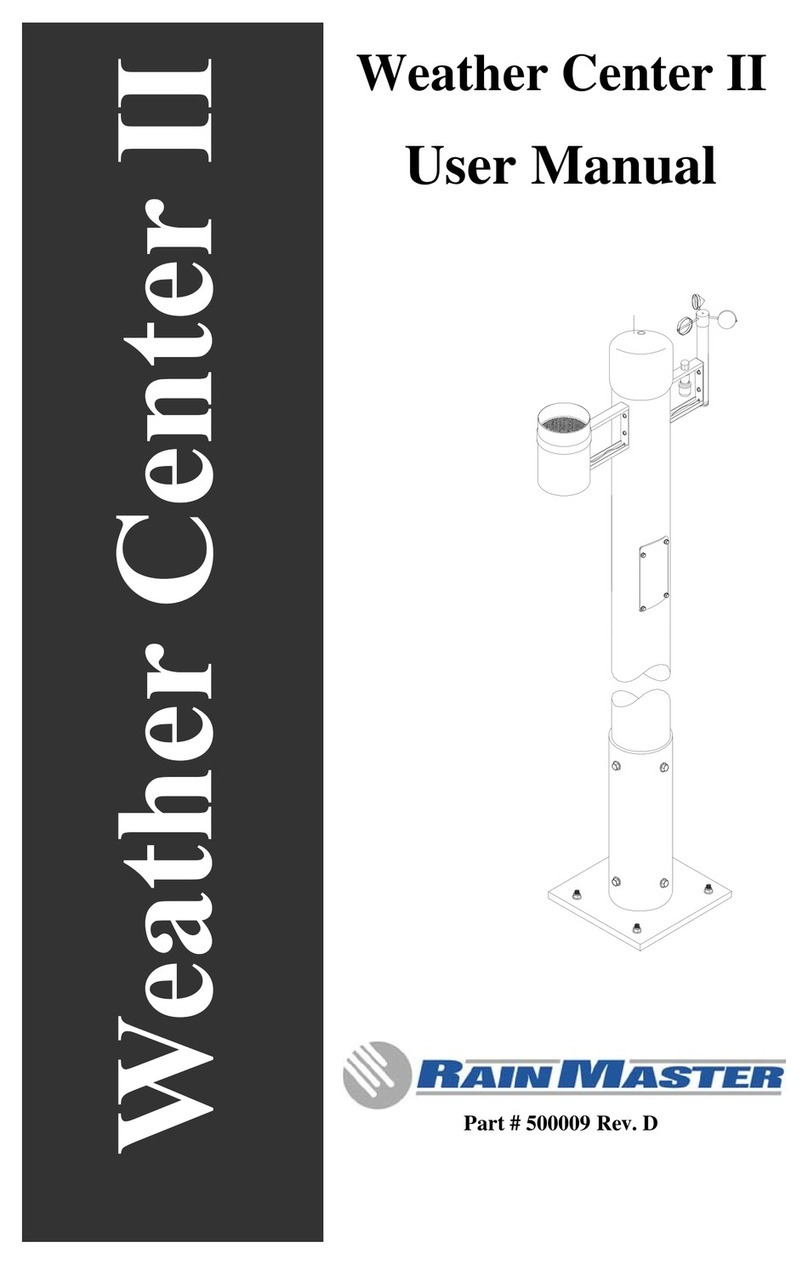
Weather Station
User Manual
ET Tracker
Rain Sensor
Wind Sensor
March 2001Document Number 500009 Rev. C


Rain Master Irrigation Systems Weather Station
Weather Station


Rain Master Irrigation Systems Weather Station Manual
Page i
Table of Contents
1.0 Introduction .............................................................................................................2
1.1 Determining Weather Station Location ...............................................................4
1.2 General...............................................................................................................5
2.0 Weather Station Installation...................................................................................5
2.1 ET Tracker Batteries.........................................................................................12
2.2 ET Tracker Mounting ........................................................................................16
2.3 Evolution DX2 Controller Wiring........................................................................16
3.0 Weather Station Instrumentation.........................................................................17
3.1 ET Tracker........................................................................................................17
3.1.1 Features and Benefits ...............................................................................17
3.1.2 ET Tracker Theory of Operation................................................................18
3.1.3 ET Tracker Specifications..........................................................................19
3.1.4 Reading ET Values At The DX2 Controller................................................20
3.2 Rain Sensor......................................................................................................20
3.2.1 Features and Benefits ...............................................................................20
3.2.2 Rain Sensor Theory of Operation..............................................................21
3.2.3 Rain Sensor Installation.............................................................................21
3.2.4 Rain Sensor Information............................................................................21
3.2.5 Satellite Rain Sensor Interfacing ...............................................................21
3.2.6 Reading Rain Sensor Values at the Evolution DX2 Controller...................22
3.3 Wind Sensor .....................................................................................................22
3.3.1 Features and Benefits ...............................................................................22
3.3.2 Wind Sensor Installation Checks...............................................................22
3.3.3 Wind Sensor Information...........................................................................22
3.3.4 Evolution DX2 Controller Wind Sensor Interfacing....................................23
3.3.5 Reading Wind Values at the DX2 Controller..............................................23
4.0 Maintenance ..........................................................................................................23
4.1 ET Tracker Maintenance...................................................................................23
4.1.1 Adding Distilled Water ...............................................................................23
4.1.2 Cleaning the Ceramic Cup Assembly........................................................23
4.1.3 Cleaning the Canvas Cover.......................................................................23
4.1.4 Hard Ceramic Evaporation Plates .............................................................23
4.1.5 Sanding the Top Surface of the Cup .........................................................24
4.1.6 Testing the Cup for Performance...............................................................24
4.1.7 Wafer Evaporation Element for Canvas Covers........................................24
4.1.8 Bird Wires..................................................................................................25
4.1.9 Checking the Plumbing for Debris .............................................................25
4.1.10 Battery Backup Replacement..................................................................25
4.1.11 Seasonal Draining ...................................................................................26
4.1.12 Freeze Protection....................................................................................26
4.2 Tipping Bucket Rain Gauge Maintenance.........................................................26
4.3 Anemometer Maintenance................................................................................26

Weather Station Manual Rain Master Irrigation Systems
Page ii
5.0 Troubleshooting....................................................................................................27
5.1 Unusually High or Low ET Readings ................................................................27
5.2 Troubleshooting Flow Charts............................................................................27
5.2.1 Symptom: Low ET Reading.......................................................................28
5.2.2 Symptom: No ET Reading.........................................................................29
5.2.3 Symptom: No Rain Reading......................................................................31
5.2.4 Symptom: No Wind Reading .....................................................................33
5.3 Verification of ET Tracker Electronics...............................................................35
5.4 Rain Sensor Reading Checkout Procedure......................................................36
5.5 Verification of Rain Gauge Electronics..............................................................36
5.6 Wind Sensor Checkout Procedure....................................................................37
Table of Figures
Figure 1: Weather Station Configuration.........................................................................3
Figure 2: Weather Station Tower Base ...........................................................................6
Figure 3: Tower Base Mounting ......................................................................................7
Figure 4: Sensor Mounting Configuration........................................................................8
Figure 5: Tower Terminal Block ......................................................................................9
Figure 6: Weather Station to Controller Connections....................................................10
Figure 7: ET Tracker Components................................................................................11
Figure 8: Assemblying the Top Cup..............................................................................12
Figure 9: Top Cup Assemby..........................................................................................13
Figure 10: Cup Immersion.............................................................................................13
Figure 11: ET Electronics Circuit Board ........................................................................14
Figure 12: Filling the Syringe.........................................................................................15
Figure 13: Attaching the Tube......................................................................................15
Figure 14: Weather Station Evolution DX2 Controller ...................................................17
Figure 15: Bird Wire Installation....................................................................................25

Weather Station Manual Rain Master Irrigation Systems
Page 2
1.0 Introduction
The Weather Station is comprised of three major measuring devices, these include:
•The ET Tracker
•The Tipping Bucket Rain Gauge
•The Wind Speed Sensor (Anemometer)
The Weather Station measures evapotranspiration (ET), rain and wind speed.The
measured values are transmitted to the Rain Master Evolution Central Computer
system via the attached Evolution DX2 Controller. The evolution central computer uses
the weather data to recalculate the irrigation schedules for all satellites associated with
a particular microclimate. The schedule in turn are downloaded to the field irrigation
controllers.
Each of the measuring devices are permanently mounted onto a vandal-resistant tower
with all connections made within the tower’s terminal block. Power for the ET Tracker is
supplied via the controller to which the Weather Station is connected. Figure 1: Weather
Station Configuration illustrates the complete Weather Station configuration.

Rain Master Irrigation Systems Weather Station Manual
Page 3
Figure 1: Weather Station Configuration

Weather Station Manual Rain Master Irrigation Systems
Page 4
1.1 Determining Weather Station Location
A general rule for determining the best location for the Weather Station is to locate the
Weather Station in an area that best represents the watering needs and changes of all
the irrigation zones. The following general rules will help you determine the best
location:
Mount in an open area, clear of all obstructions. The area should be in direct sunlight,
away from buildings, trees or other objects which may restrict wind movement or cast
shadows.
Avoid locations that will generate reflective heat (buildings, parking lots, roadways, etc.)
Excessive heat generated from these objects will cause distorted ET readings.
Locate in an area that will prevent the top evaporating surface from getting wet from the
irrigating water.
Table 1: Weather Station Parts List
Part Number Description Quantity
EV-SEN-WD Anemometer Assembly 1
EV-SEN-TRKR E.T. Tracker Assembly 1
EV-SEN-RN Rain Guage Assembly 1
ET-PS Power Supply, 6V DC Reg. 1
ET-610 Hand Tool, 610 OW Remove 1
020-0104 Tower, ET/Wethr, 10 foot 1
020-0106 Cap, PVC, Round 1
460-0001 Batteries AA for the ET Tracker 4
500009-C Manual, Weather Station 1
Table 2: Required Equipment/Tools
Part Number Description Quantity
DX-FLOW
or
DX-MOIST
Evolution DX2 Controller equipped with
option DXFLOW (Flow and Weather
sensing) or DX_MOIST (Flow, Moisture
and Weather sensing) 1
EV-CAB-WS
Cable, 8 conductor, 18 gauge
stranded, foil shield w/drain, direct
burial. (Order to length, maximum
length 1,000 ft.) 1
Crescent wrench 1
3/8, 5/16, 7/16 inch socket wrench 1
Screwdriver, flat blade 1

Rain Master Irrigation Systems Weather Station Manual
Page 5
8 foot step ladder 1
PVC Conduit 1 inch, for tower base
wiring. 4 feet
PVC 1 inch elbow 1
Water container, for Top cup assembly
immersion 1
Table 3: Required Materials
Part Number Description Quantity
Concrete and masonary Sand 1
Standard masonary tools 1
Gallon of Distilled Water 1
1.2 General
The mounting bolts for the Rain Gauge, Wind Sensor and tower mounting bracket, are
pre-installed on the tower mast. These bolts will need to be removed prior to assembly
and installation.
2.0 Weather Station Installation
Use the following step to assembly the Weather Station tower.
Step 1 Prepare and pour a concrete support slab according to the enclosed
drawing, see Figure 2: Weather Station Tower Base. Use the provided
template to set the 5/16" mounting bolts. The bracket must be level
and plumb. The conduit should extend at least 2 inches above the
horizontal plate.
Step 2 Install the 8 conductor cable (EV-CAB-WS) from the controller to the
Weather Station through the conduit. From the Weather Station to the
controller allow a minimum of 36 inches of cable to extend beyond the
conduit into the controller’s pedestal cabinet. On the Weather Station
tower, allow a minimum of 70 inches of cable to extend beyond the
conduit into the Weather Station mast assembly.

Weather Station Manual Rain Master Irrigation Systems
Page 6
Figure 2: Weather Station Tower Base

Rain Master Irrigation Systems Weather Station Manual
Page 7
Step 3 Attach the tower to the Weather Station mounting bracket using the 3/8
inch cross-bolts (see Figure 3: Tower Base Mounting).
Figure 3: Tower Base Mounting
Step 4 Using a 7/16 inch socket wrench, remove the four Rain Gauge and
Anemometer mounting bolts from the tower mast. Attach the Tipping
Bucket Rain Gauge to the tower and insert the signal cable, with
connector, through the 5/8 inch hole in the side of tower (See Figure 4:
Sensor Mounting Configuration).

Weather Station Manual Rain Master Irrigation Systems
Page 8
Figure 4: Sensor Mounting Configuration
Step 5 Attach the wind cup assembly to the anemometer and secure the
assembly to the spin shaft using the supplied allen wrench.
Step 6 Attach the Anemometer to the tower and insert the signal cable, with
connector, through the 5/8 inch hole in the side of tower. (See Figure
4: Sensor Mounting Configuration)

Rain Master Irrigation Systems Weather Station Manual
Page 9
Figure 5: Tower Terminal Block
Step 7 Remove the lower access plate using the supplied hand tool (ET-610).
Drop the cable all the way down the tower mast until it is accessible
through the lower access panel. Mate the connectors to the Weather
Station terminal bracket connectors (See Figure 5: Tower Terminal
Block and Figure 6: Weather Station to Controller Connections).

Weather Station Manual Rain Master Irrigation Systems
Page 10
Figure 6: Weather Station to Controller Connections

Rain Master Irrigation Systems Weather Station Manual
Page 11
Figure 7: ET Tracker Components
Evaporation Plate
Top Cup Assembly
Pinch Clamp
Stopper
Reservoir
PVC Pipe
Distilled Water
Rubber Tube
ET Tracker
Electronics Bd.
Lower Enclosure
Cover

Weather Station Manual Rain Master Irrigation Systems
Page 12
Figure 8: Assemblying the Top Cup
2.1 ET Tracker Batteries
Step 1 Refer to Figure 7: ET Tracker Components. Locate the ET Tracker
assembly. Release the two bottom retaining clips and remove the
lower enclosure cover to expose the Tracker electronics. Install the
four provided alkaline batteries (size AA) in the battery holder with the
positive (+) end pointing towards the red side of the holder.
Step 2 Refer to Figure 7: ET Tracker Components. Release the retaining
clips and remove the top cup assembly from the reservoir.
Step 3 Make sure the canvas cover is contoured to fit the ceramic cup. (See
Figure 8: Assemblying the Top Cup)
CAUTION: It is important to fit the canvas cover tightly to the ceramic cup
so there are NO air spaces between the canvas cover and the
evaporation plate (See Figure 9: Top Cup Assemby).

Rain Master Irrigation Systems Weather Station Manual
Page 13
Figure 9: Top Cup Assemby
Step 4 Remove the rubber stopper from the top cup assembly. Pour distilled
water to completely fill the cup. Next, place the filled cup into a suitable
container and completely immerse the top cup assembly in distilled
water. Allow the cup to soak for at least 30 minutes. Refer to Figure 10:
Cup Immersion.
Figure 10: Cup Immersion
Step 5 While cup is soaking, fill the reservoir (PVC pipe section) with distilled
water. Fill it to a level approximately 1 inch from the top of the PVC
pipe section.
Canvas
Stopper
Evaporation
Plate
Glass
Tube

Weather Station Manual Rain Master Irrigation Systems
Page 14
Figure 11: ET Electronics Circuit Board
Step 6 Priming Process
Refer to Figure 7: ET Tracker Components. Release the two bottom
retaining clips and remove the lower enclosure to expose the tracker’s
electronic board assembly.
Refer to Figure 11: ET Electronics Circuit Board. Hold the assembly
upright and press the push-button switch at the lower left corner of the
circuit board to activate the valve. While holding the push-button in,
allow the water to flow through the glass vial until it is clear of all air
bubbles, then release the switch.
Step 7 Refer Figure 12: Filling the Syringe. With the syringe attached to the
upper end of the rubber tube, draw water slowly through the tube until
the tube is completely full of water and free of all air bubbles. When
full, pinch the tube closed with the plastic pinch clamp located just
below the syringe.
Glass Vial
Push-button
Switch

Rain Master Irrigation Systems Weather Station Manual
Page 15
Figure 12: Filling the Syringe
Step 8 Remove the syringe from the rubber tube.
Step 9 With the rubber tube disconnected from the stopper, push and twist the
rubber stopper tightly into the cup.
Note: Ensure that the ceramic cup assembly is completely full of water
before insertion of the rubber stopper.
Step 10 Refer to Figure 13: Attaching the Tube. Using the top cup assembly from
Step 5. Carefully attach the tube to the glass protruding from the stopper
without spilling the water from either assembly.
Figure 13: Attaching the Tube
Syringe
Pinch
Clamp
This manual suits for next models
2
Table of contents
Other RainMaster Weather Station manuals
Popular Weather Station manuals by other brands

La Crosse Technology
La Crosse Technology C85845v4 instruction manual

Eurochron
Eurochron EFWS5008 operating instructions

La Crosse Technology
La Crosse Technology WS-9025U instruction manual

Hama
Hama WFC 310 instruction manual

La Crosse Technology
La Crosse Technology Wireless Weather Station instruction manual

La Crosse Technology
La Crosse Technology WS-9005TWC-IT instruction manual