DN200 Weatherstation Installation Manual Revision B Page 4
Site Orientation
Poles and cross member must be in an E-W orientation this will allow for the following:
Wind vane and anemometer –North Facing
Black globe thermometer –North Facing
Rain gauge, air temperature, humidity and solar radiation (unobstructed) sensors –South
Facing
Solar panel –North Facing
Enclosure –South Facing
Construction Order:
Orient the oppositions of the steel posts to E-W
The steel posts must be as close as possible to 1150mm apart (tip to tip)
Embed steel posts with only 1m remaining out of the ground.
Attach the 2m posts to the steel post using two hose clamps provided –one at 100mm from
the ground and the other at the top of the steel post (~1m above the ground) ensuring it is
well below the drilled hole.
Align the lowest holes in the poles toward each other to allow for wiring to pass into the
cross member.
Mount the Davis and Environdata sensors to the WS Pole Left and run the wind cable under
the rain gauge then into Davis control box. Connect at the labelled location. The Console
cable must be also be connected then the foam plug refitted inside the Davis control box.
Tools required 11mm spanner, 10mm spanner and 10mm socket.
Pass the console (Davis) and Black globe cables through the rubber grommets and the
appropriate drilled holes leaving them exiting the pole at the cross member position. Don’t
forget to thread and fit another grommet to sit inside the cross member.
Cable tie if necessary.
Fit out the solar panel with two brackets and cross member using the 6 off M8 x 20mm bolts
provided. Attach the bird deterrent to the top of the panel using two 4mm tek screws
provided. Mount the panel together with the antenna bracket (facing backwards) on the DN
Pole Right. See photos. Tools required –two 13mm spanners and a 13mm socket
Mount the enclosure about 50mm higher than the cable exit hole (on the southern side of
the pole). Tools required 13mm socket.
Mount the antenna (either 4G or Satellite) and pass both the antenna and solar panel cable
down through the top of the pole to the exit hole under the enclosure. The GPS and 4G
antenna are different sizes and t is useful to have a 14mm spanner and 17mm spanner
available or carry a shifting spanner.
Pass the solar panel and antenna cables down through the pole and exit underneath the
enclosure. You may need to use a cable draw to assist with this.
If necessary, cable tie the solar panel cable to its bracket and place another cable tie around
it and the antenna cable to secure their position in the top of the pole.
Draw the weather station cables through the 2” cross member and pass them into the DN
pole then up to the enclosure exit. Again you will likely need to use a cable draw to assist.
Make sure you fit a rubber grommet to the cables once they exit the cross member so that it
can be fitted into the pole.
Fit the cross member using the galvanised T Clamps provided.
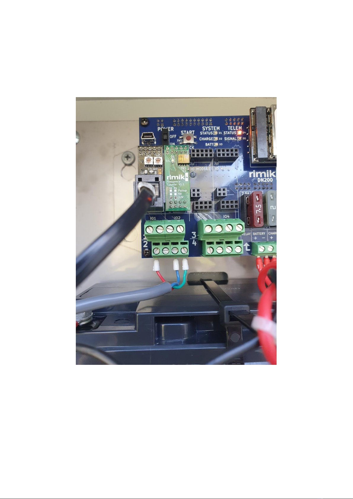
You should now be ready to wire the cable into the DN200.