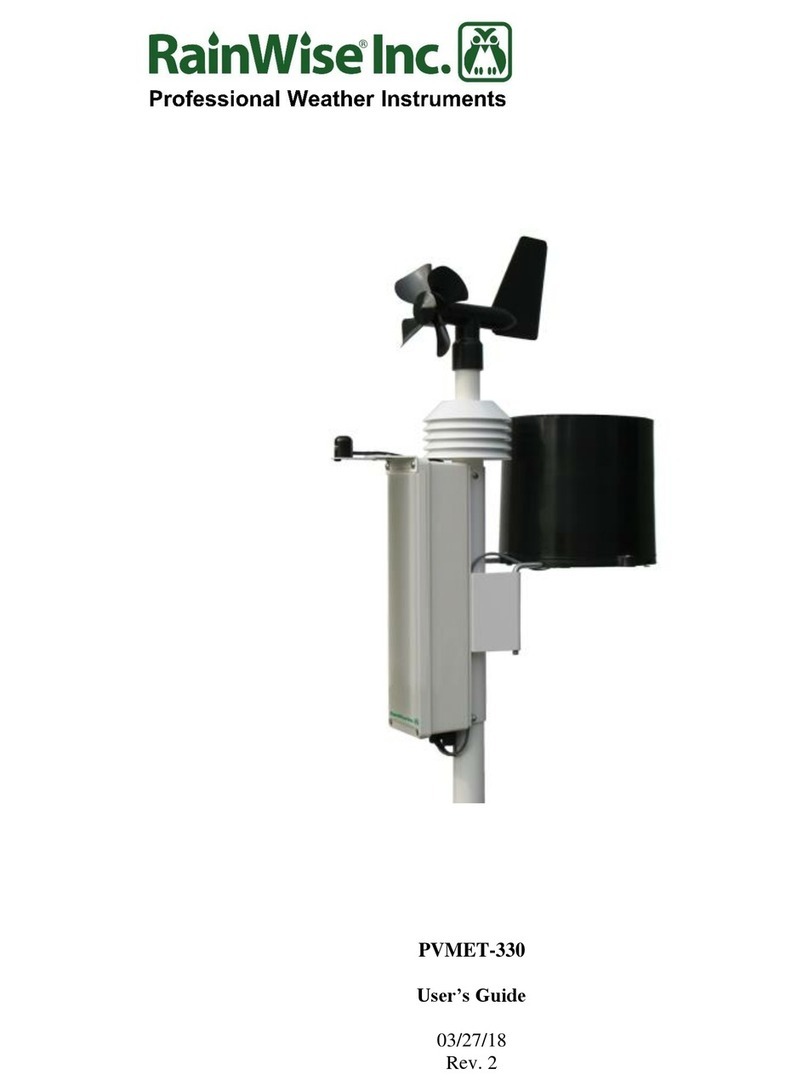
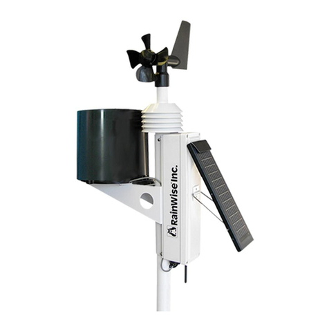
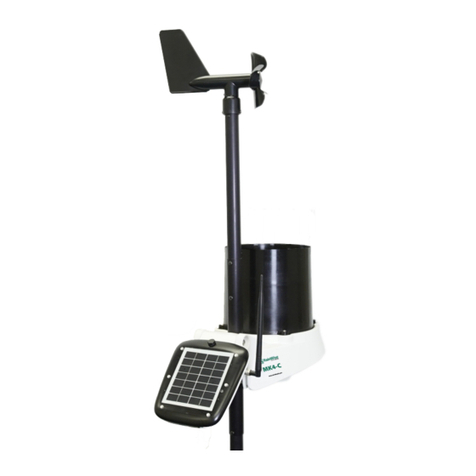
RainWise MKIII-MB User manual

MKIII™-MB
USER’S GUIDE
09/18/18
Rev. 3

- 2 -
Copyright © 2018 by RainWise, Inc.
All rights reserved. No part of this work may be reproduced in any form except by written permission of
the publisher. All rights of translation are reserved.
MKIII™ is a trademark of RainWise, Inc.

- 3 -
INTRODUCTION .................................................................................................................................. 5
INSTALLING THE WEATHER STATION......................................................................................... 5
SITE REQUIREMENTS AND CONSIDERATIONS......................................................................................................... 5
INSTALLATION ................................................................................................................................................ 5
Weather Station..................................................................................................................................... 5
Anemometer .......................................................................................................................................... 7
WIRING ........................................................................................................................................................ 7
Connecting RS-485 ............................................................................................................................... 7
Connecting the Power Supply............................................................................................................... 7
MODBUS RTU............................................................................................................................................. 8
COMMUNICATIONS ......................................................................................................................................... 8
SCALING........................................................................................................................................................ 8
UNSUPPORTED FIELDS...................................................................................................................................... 8
POWER MANAGEMENT ............................................................................................................................. 8
MODBUS MAP............................................................................................................................................ 9
CHANGING THE MODBUS DEVICE ADDRESS ....................................................................................................... 10
CHANGING THE BAUD RATE............................................................................................................................ 10
SOFTWARE/FIRMWARE UPDATES ............................................................................................... 10
MINIMUM SYSTEM REQUIREMENTS........................................................................................... 11
RS-485................................................................................................................................................. 11
Software.............................................................................................................................................. 11
Sensor Assembly: ................................................................................................................................ 11
Enclosure:........................................................................................................................................... 11
Ambient Air Temperature Sensor: ...................................................................................................... 12
Electronics:......................................................................................................................................... 12
Physical: ............................................................................................................................................. 12
HARDWARE SPECIFICATIONS ................................................................................................................. 13
OPERATING ENVIRONMENT: ........................................................................................................................... 13
AMBIENT AIR TEMPERATURE SENSOR:.............................................................................................................. 13

- 4 -
RELATIVE HUMIDITY:..................................................................................................................................... 13
BAROMETRIC PRESSURE:................................................................................................................................ 13
ANEMOMETER (REED SWITCH)........................................................................................................................ 13
WIND DIRECTION: ........................................................................................................................................ 13
WIND SPEED: .............................................................................................................................................. 14
LIQUID PRECIPITATION:.................................................................................................................................. 14
SOIL TEMPERATURE: ..................................................................................................................................... 14
WARRANTY........................................................................................................................................ 15

- 5 -
INTRODUCTION
The MKIII-MB weather station is a compact and economical solution for weather monitoring. It measures
ambient air temperature, relative humidity, barometric pressure, wind speed and direction, rainfall, and is
capable of measuring up to 2 soil or other peripheral temperatures, solar radiation, and UV Index. The
MKIII-MB uses a 2-wire half duplex RS-485 serial port for Modbus RTU communication with a host.
INSTALLING THE WEATHER STATION
It is suggested that the system is operated at ground level to make sure that all components are working
properly prior to installation.
If any of the components are damaged or malfunctioning upon receipt, RainWise should be contacted.
SITE REQUIREMENTS AND CONSIDERATIONS
Ambient air temperature, solar radiation, and wind speed and direction can be affected by obstructions
and local topography. Each site is different and presents challenges in its own unique way. The MKIII-MB
sensor assembly, which contains the ambient air temperature and wind speed and direction sensor,
should be no closer than 10 times any obstruction’s height and should be placed away from any dark,
heat-absorbing surface.
When roof-mounting the sensor assembly, the unit should be mounted toward an edge of the roof
preferably on the prevailing wind side of the building and should be at least 2-1/2 feet above the roofline.
Avoid locating the station near any heat sources such as chimneys or vents.
INSTALLATION
WEATHER STATION
Mount the support mast securely to a support structure. This may be done by using the Mono-Mount,
which is sold as an accessory to the MKIII-MB. The mast may also be attached to a support structure using
U-Bolts. Do not tighten the support structure to the MKIII-MB unit, as directional orientation will be
required.
Rotate the assembled unit until the electronics enclosure cover faces TRUE SOUTH if you are in the
northern hemisphere, or TRUE NORTH if you are in the southern hemisphere. Secure the support mast to
the assembly. Rotation is prevented by lining up the two holes in each mast. At this point, the entire unit
should be secured to the support structure. It is crucial that the device is oriented as precisely as possible.
The wind direction measurement is directly related to this positioning.

- 6 -
NOTE: The station is set for use in the northern hemisphere by default. If using the station in the southern
hemisphere you must place switch #3, located on the motherboard inside the enclosure, in the ON
position.

- 7 -
ANEMOMETER
The anemometer is directly attached to the top of the sensor assembly. For correct wind direction
operation, the MKIII-MB must be oriented correctly.
By default, the MKIII-MB is configured for operation in the Northern hemisphere. This only requires that
the optional solar radiation sensor faces due South. If the MKIII-MB is going to be used in the Southern
hemisphere it must be mounted with the solar radiation sensor facing North. In addition, the hemisphere
jumper inside the MKIII-MB must be changed from Northern to Southern as shown in the image be in the
wiring section.
WIRING
To enter the enclosure with a cable, the front cover must first be removed. Remove the four Philips head
screws from the back of the enclosure. Once the lid is removed, the circuit board is exposed.
CONNECTING RS-485
The MKIII-MB is supplied with a half-duplex RS-485 serial port. Wiring connections are made using the 4-
pin screw terminal inside of the MKIII-MB electronics enclosure. Cable is not supplied with the unit. The RS-
485 lines can be terminated with a 120-ohm resistor. This can be enabled by moving the termination
jumper, located inside the unit, to the “ON” position. This requires removing the enclosure cover.
RS-485 TERMINALS
A (-): Negative RS-485
B (+): Positive RS-485
GND: Signal/Power Ground
+VDC: External 10-30VDC Supply
RS-485 is rated to 4,000 feet (1,200 m) at 90 kbps. The RS-485 port on the MKIII-MB is surge protected but
not isolated.
CONNECTING THE POWER SUPPLY
The weather station must be powered by an external power source unless the solar-powered option has
been purchased. For systems running with external power, a cable connection must be made between the
RS-485 interface board and the motherboard. A cable is provided and should already be connected to J2
on the RS-485 board.

- 8 -
The power supply input is nominally rated for 24VDC but can accept a voltage in the range of 10 to
30VDC. The inputs are reverse polarity, surge, overvoltage, and overcurrent protected. The power supply
is not isolated.
MODBUS RTU
These weather stations are equipped with an RS-485 communications port that supports a subset of Modbus
RTU commands. Two baud rates are supported 9600 and 19,200. Only 4X Holding registers are supported.
The register map that follows describes each register. These stations are read-only.
COMMUNICATIONS
Baud: Switch 5 selects the baud rate. ON=19200, OFF=9600 (default).
Data bits: 8
Parity: None
Stop Bits: 1
Maximum Poll Rate: 5 Hz (Extended periods of rapid polling will drain the battery)
SCALING
Parameters are reported as integers. In order to maintain resolution, some values are scaled up. The scale
factor shown indicate how the value should be scaled or multiplied by. Rainfall is an exception, this
parameter reports the number of tips of the tipping bucket rain gauge. Typically the gauge is calibrated to
0.254mm (0.01”) per tip. This counter resets on a reboot and will roll over at 65536 counts.
UNSUPPORTED FIELDS
The register map reserves registers for all combinations of sensors supported by the Rainwise stations. Not
all will be available on any one system. Sensors/fields that are not supported will contain the value 0x8000.
Some fields require the purchase of additional sensors. The values reported by fields that don’t have valid
sensors installed should be ignored.
POWER MANAGEMENT
The weather station will enter a low power mode when the RS-485 bus is quiet. The station will wake on
any activity and will remain awake drawing full power for 3 seconds after the last activity on the bus.
When using the weather station with its own solar power the bus should remain inactive for the majority of
the time. Suggested polling rates are between 1 and 5 minutes. The battery voltage can be monitored to
assess the station health. Readings below 6 volts indicate a low battery. 5.8 volts is considered critical.
If the station is supplied with auxiliary power the above is not applicable and the station can be polled as
often as desired.
In DC powered stations the RS-485 interface board supplies the main board with a regulated 6.8V DC
supply. This is the voltage reported in the Modbus Supply Voltage Modbus register.

- 9 -
MODBUS MAP
Holding
Register
Item
Type
Units
Scale
Factor
Contents
0
Manufacturer
uint16
N/A
"RW" (0x5257)
1
Model
uint16
N/A
"S0"=MK-III, "S1"=MKIII,
"S2"= PVmet
2
Version
uint16
N/A
0x0170, "01" Map Version,
"70" Firmware Version
3
Air Temperature
int16
Degrees C
0.1
Measured
4
Humidity
int16
%
1.0
Measured
5
Pressure
int16
hPa
0.1
Measured
6
Wind Speed
int16
m/s
0.1
Measured
7
Wind Direction
int16
Degrees
1.0
Measured
8
Wind Speed 5min Avg.
int16
m/s
0.1
Measured
9
Wind Direction 5 min Avg.
int16
Degrees
1.0
Measured
10
Wind Gust (5 min)
int16
m/s
0.1
Measured
11
Wind Gust Direction
int16
Degrees
1.0
Measured
12
Rainfall
int16
Counter
1.0
Measured
13
Aux Temperature 1
int16
Degrees C
0.1
Measured
14
Aux Temperature 2
int16
Degrees C
0.1
Measured
15
-
int16
-
0x8000
16
-
int16
-
-
0x8000
17
-
int16
-
-
0x8000
18
Solar Irradiance
int16
W/m2
1.0
Measured
19
-
0x8000
20
UV Index
int16
N/A
0.1
Measured
21
-
Int16
-
-
0x8000
22
Supply Voltage
int16
Volts
0.01
Measured

- 10 -
CHANGING THE MODBUS DEVICE ADDRESS
The Modbus device can be changed using the dip switches 1 & 2 with the default position set to device
address 60.
Modbus Address
Switch 1
Switch 2
60
0
0
61
1
0
62
0
1
63
1
1
CHANGING THE BAUD RATE
The baud rate can be set to either 9600 or 19200. The default baud rate is 9600. Changing the dip switch
to the ON position will change the baud rate to 19200.
SOFTWARE/FIRMWARE UPDATES
The software or firmware in the MKIII-MB can be updated or changed using the RS-485 port. Make sure
you read the update instructions carefully and be sure you are installing the correct software. As with all
updates, there are risks associated with changing the flash memory.
Updates are loaded using a Windows-based program called IAP flash. This program is supplied with the
“.enc” file along with instructions. Windows is required to perform updates. No other operating systems
are currently supported.

- 11 -
MINIMUM SYSTEM REQUIREMENTS
The MKIII-MB is equipped with an RS-422/485 serial port.
RS-485
Baud rate: 9600/19,200 bps
Parity: None
Data bits: 8
Stop bits: 1
Flow Control: None
Interface mode: 2-Wire Half Duplex
SOFTWARE
The MKIII-MB is designed to work with an RS-422/485 compliant host. A terminal emulator program is
required to change settings.
Material Specifications
SENSOR ASSEMBLY:
RoHS Compliant
Mast: Polyvinyl Chloride
Heat Shields: Acrylonitrile Butadiene Styrene
Insolation Sensor Bracket: Delrin
Hardware: Stainless Steel and Nylon Locknut
Foam Gasket: Vinyl and Acrylic
ENCLOSURE:
RoHS Compliant
IP65 Rated Outdoor Enclosures
UL 94 V-2
Body: Polycarbonate

- 12 -
AMBIENT AIR TEMPERATURE SENSOR:
RoHS Compliant
ELECTRONICS:
RoHS Compliant
PHYSICAL:
Packaged Weight: 7 lbs
Packaged Dimensions: 6cm x 20.3cm x 20.3cm (10.25” x 8” x 8”)

- 13 -
HARDWARE SPECIFICATIONS
OPERATING ENVIRONMENT:
Temperature: -40 ~ 70°C (-40 ~ 158°F)
Humidity: 0 ~ 100% Condensing
AMBIENT AIR TEMPERATURE SENSOR:
Range: -55 ~ 85°C (-67 ~ 185°F)
Accuracy: ±0.2°C at 25°C (±0.4°F at 77°F)
Resolution: 0.056°C (0.1°F)
RELATIVE HUMIDITY:
Operational Temperature: -40 ~ 70°C (-40 ~ 158°F)
Range: 0 ~ 100%
Accuracy: ±2% for 10 ≤ %RH ≤ 90 at 25°C (77°F)
±4% for 10 > %RH > 90 at 25°C (77°F)
Resolution: 1%
BAROMETRIC PRESSURE:
Operational Temperature: -40 ~ 85°C (-67 ~ 185°F)
Range: 300 ~ 1100 mbar (8.86 ~ 32.49 inHg)
Accuracy: ± 0.5 mbar between 700-1100 mbar at 25°C
(±0.015 inHg between 20.67 ~ 32.49 inHg. at 77°C)
Resolution: 0.34 mbar (0.01 inHg)
ANEMOMETER (REED SWITCH)
Operational Temperature: -40 ~ 85°C (-40 ~ 185°F)
Anemometer Extension: Up to 15.24m (50ft)
WIND DIRECTION:
Range: 0 ~ 360°
Accuracy: ±11.25°
Resolution: 22.5°

- 14 -
Starting Threshold: 1.98 m/s (4.43 mph)
WIND SPEED:
Range: 0 ~ 67 m/s (0 ~ 150 mph)
Accuracy: Greater of 0.45m/s (1 mph) or 5% of Reading
Resolution: 0.045 m/s (0.1 mph)
Threshold: 0.65 m/s (1.45 mph)
LIQUID PRECIPITATION:
Operational Temperature: 0 ~ 85°C (0 ~ 185°F)
Range: 0 ~ 762 mm/hr (0 ~ 30 in/hr)
Accuracy: ±2% at 25.4 mm/hr (±2% at 1 in/hr)
Resolution: 0.254 mm (0.01 in)
SOIL TEMPERATURE:
Range: -55 ~ 85°C (-67 ~ 185°F)
Accuracy: ±0.2°C at 25°C (±0.4°F at 77°F)
Resolution: 0.056°C (0.1°F)

- 15 -
Contact Information
RainWise Inc.
18 River Field Rd,
Trenton, ME 04609 USA
Phone: (207)-288-5169
WARRANTY
RainWise, Inc. warrants RainWise, Inc. manufactured MKIII products against defects in materials and/or
workmanship for a period of two years from the date of purchase and agrees to repair or replace any
defective product without charge. Equipment supplied by RainWise but not manufactured by RainWise is
covered by the particular warranty of that manufacturer.
IMPORTANT: This warranty does not cover damages resulting from accident, misuse or abuse, lack of
reasonable care, the fixing of any attachment not provided with the product or damage due to a lightning
strike or power surge. RainWise, Inc. will not reimburse for take-down or installation charges. RainWise,
Inc. will not pay for warranty service performed by a non-authorized repair service and will not reimburse
the consumer for damage resulting from warranty service performed by a non-authorized repair service.
No responsibility is assumed for any special, incidental or consequential damages.
To return a unit under this warranty, call (800) 762-5723 within the continental US or (207) 288-5169. The
service department will document the need for repair/replacement and arrange such. Shipping costs
from the customer to RainWise are borne by the customer, RainWise will cover return shipment. It is the
customer's responsibility to see that the unit is properly packed, preferably in the original box, because
damage occurring during return shipment is not covered by this warranty.
NOTE: No other warranty, written or oral, is authorized by RainWise, Inc. This warranty gives you specific
legal rights, and you may also have other rights, which vary from state to state. Some states do not allow
the exclusion of limitation of incidental or consequential damages, so the above exclusion and limitations
may not apply to you.
Table of contents
Other RainWise Weather Station manuals
Popular Weather Station manuals by other brands

Goddess
Goddess WEA 914 instruction manual

La Crosse Technology
La Crosse Technology WS-1510-IT instruction manual

Aercus
Aercus WS2073 instruction manual

Explore Scientific
Explore Scientific WSH4005-CM3LC2 instruction manual

La Crosse Technology
La Crosse Technology T83646v2 Quick setup guide

La Crosse Technology
La Crosse Technology S85814V2 Instructional manual