RTC-Bridge User Manual
For an overview of Bridges: "Bridge Application Sheet"
For programming a wireless system: "Rako App User Guide"
Contents:
1 Functions of the RTC-Bridge
2 Installing the RTC-Bridge
3 Discovering the Bridge and Setting the House Number
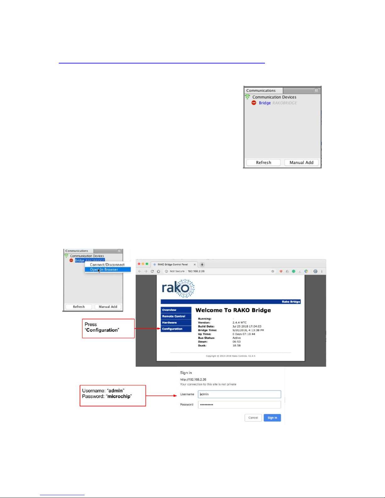
3.1 Discovering the Bridge
3.2 To set the Bridge House number
3.3 If you cannot connect to the Bridge
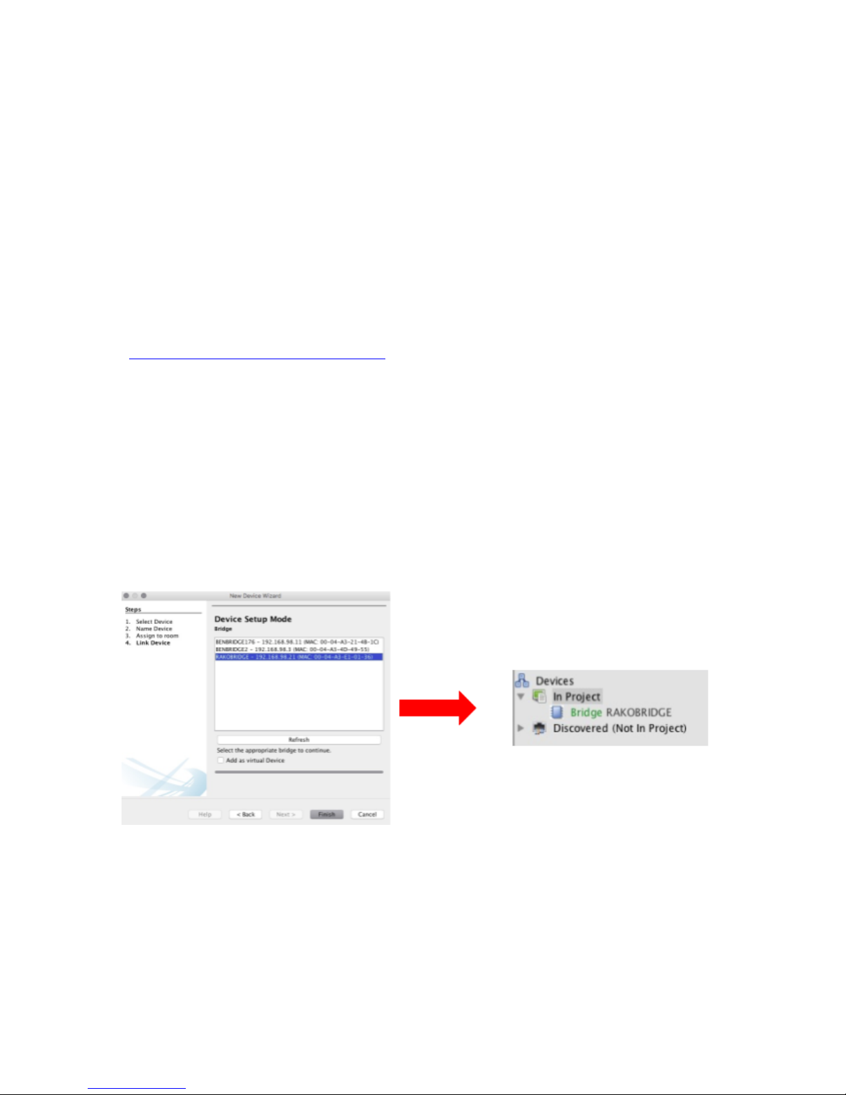
4 Adding the Bridge as a device
5 Uploading the project file
6 Downloading the project file
7 Events
Setting Events using Rasoft Pro
7.2 Setting Events using the Rako App.
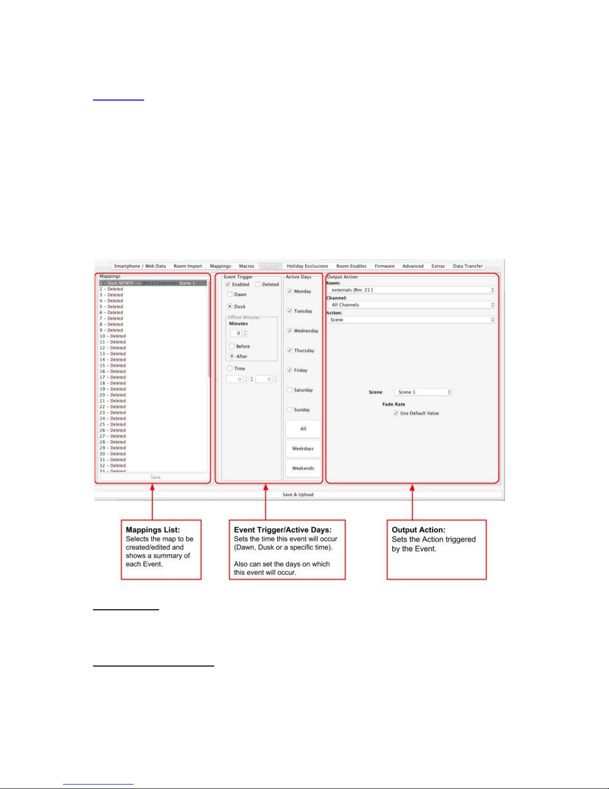
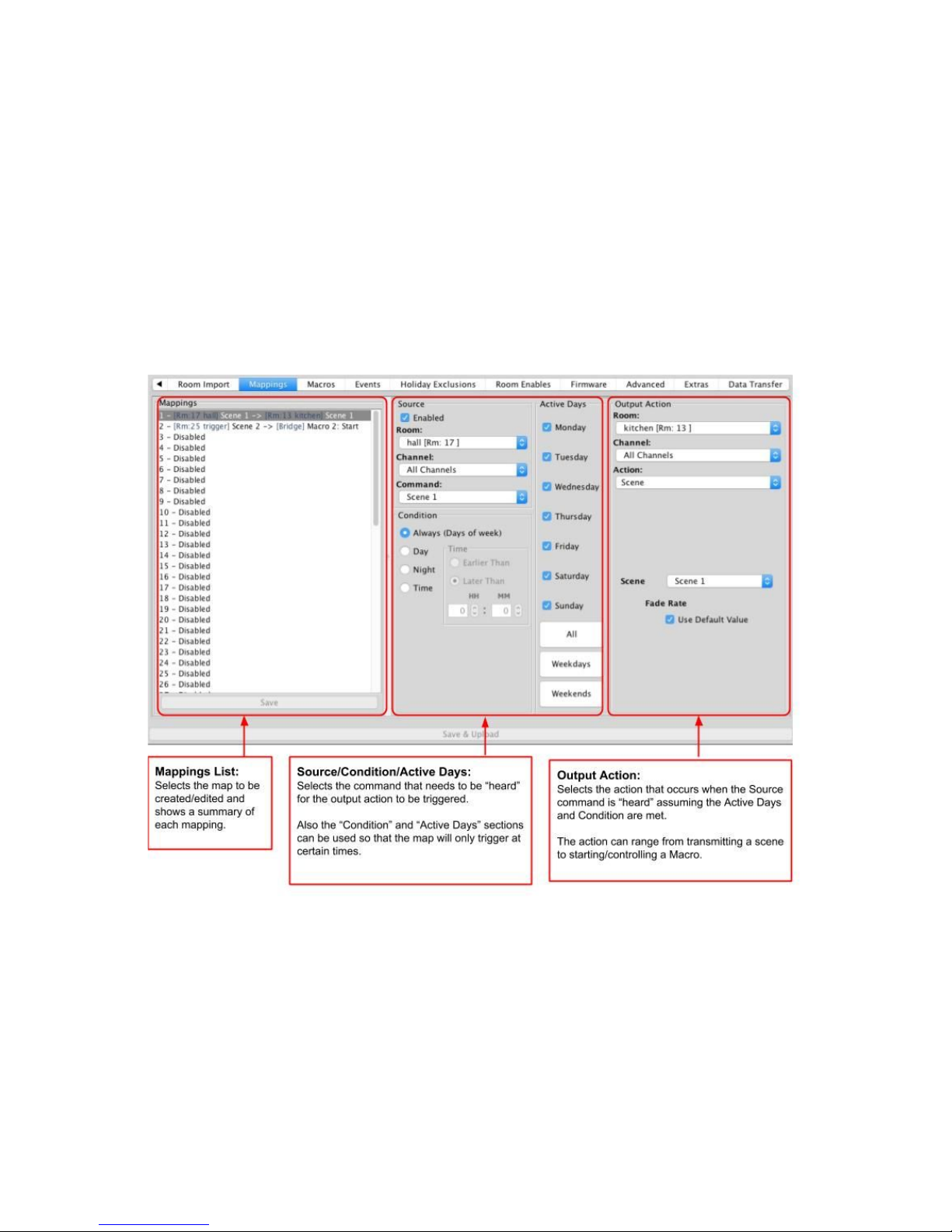
8 Mappings
Mapping wireless commands to give multi-room functionality
Triggering Macros from Maps
9 Macros
Writing Macros
Triggering Macros
10 Holiday Mode
11 UDP Feedback
7.1 Live feedback
7.2 UDP feedback log
12 Performing a Firmware upgrade
1 Functions of the RTC-Bridge
RTC-Bridge will add the following features to a RAKO wireless system:
-Network interface: including remote control via mobile devices.
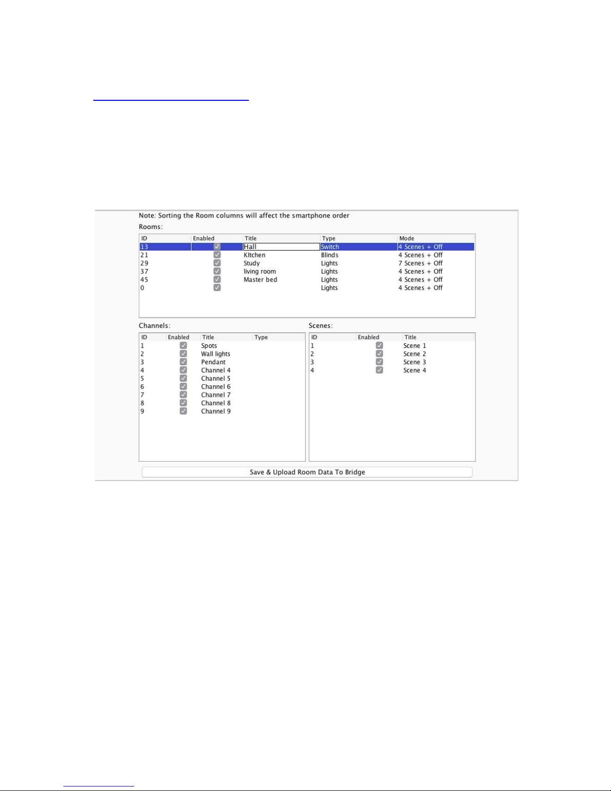
-Storing Project file information: Room, Channel and Scene information can be
stored.
-Timed Events: Automatic functions at fixed times including dawn & dusk times.
-Mapping: Commands can be redirected to perform other tasks.