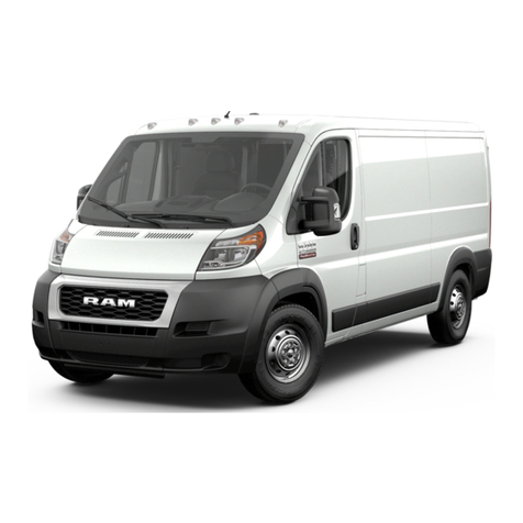
RAM 2014 RAM PROMASTER Owner's manual

ProMaster
Chrysler Group LLC
DIESEL SUPPLEMENT
2014
14VF-226-AB Second Edition Printed in U.S.A.
2014 PROMASTER DIESEL SUPPLEMENT

VEHICLES SOLD IN CANADA
With respect to any Vehicles Sold in Canada, the name
Chrysler Group LLC shall be deemed to be deleted and the
name Chrysler Canada Inc. used in substitution therefore.
DRIVING AND ALCOHOL
Drunken driving is one of the most frequent causes of
accidents.
Your driving ability can be seriously impaired with blood
alcohol levels far below the legal minimum. If you are
drinking, don’t drive. Ride with a designated non-drinking
driver, call a cab, a friend, or use public transportation.
WARNING!
Driving after drinking can lead to an accident. Your
perceptions are less sharp, your reflexes are slower,
and your judgment is impaired when you have been
drinking. Never drink and then drive.
This manual illustrates and describes the operation of
features and equipment that are either standard or
optional on this vehicle. This manual may also include a
description of features and equipment that are no longer
available or were not ordered on this vehicle. Please
disregard any features and equipment described in this
manual that are not on this vehicle.
Chrysler Group LLC reserves the right to make changes
in design and specifications, and/or make additions to or
improvements to its products without imposing any
obligation upon itself to install them on products previ-
ously manufactured.
Copyright © 2013 Chrysler Group LLC

TABLE OF CONTENTS
SECTION PAGE
1INTRODUCTION .............................................................3
2THINGS TO KNOW BEFORE STARTING YOUR VEHICLE .............................5
3UNDERSTANDING THE FEATURES OF YOUR VEHICLE ..............................7
4UNDERSTANDING YOUR INSTRUMENT PANEL ...................................9
5STARTING AND OPERATING ..................................................29
6MAINTAINING YOUR VEHICLE ................................................83
7MAINTENANCE SCHEDULE ..................................................107
8INDEX ....................................................................119
1
2
3
4
5
6
7
8


INTRODUCTION
CONTENTS
䡵A MESSAGE FROM CHRYSLER GROUP LLC ....4
1

A MESSAGE FROM CHRYSLER GROUP LLC
Chrysler Group LLC welcomes you as a turbocharged
diesel-powered vehicle owner. Your diesel vehicle will
sound, feel, drive and operate differently from a gasoline-
powered vehicle. It is important that you read and
understand this manual.
Almost 100% of the heavy trucks in the United States and
Canada are diesel-powered because of the fuel economy,
rugged durability, and high torque which permits pulling
heavy loads.
You may find that some of the starting, operating, and
maintenance procedures are different. However, they are
simple to follow and careful adherence to them will ensure
that you take full advantage of the features of this engine.
NOTE: Some aftermarket products may cause severe
engine/transmission and/or exhaust system damage.
Your vehicle’s Powertrain Control Systems can detect
and store information about vehicle modifications that
increase horsepower and torque output such as whether
or not performance-enhancing powertrain components,
commonly referred to as downloaders, power boxes, or
performance chips have been used.
This information cannot be erased and will stay in the
system’s memory even if the modification is removed. This
information can be retrieved by Chrysler Group LLC, and
service and repair facilities, when servicing your vehicle.
This information may be used to determine if repair will be
covered by New Vehicle Limited Warranty.
There is a probability that the use of a “performance
chip” will prohibit the engine from starting. In this
instance, the vehicle will need to be serviced by a
authorized dealer in order to return the vehicle to it’s
factory settings.
4 INTRODUCTION

THINGS TO KNOW BEFORE STARTING YOUR VEHICLE
CONTENTS
䡵ENGINE BREAK-IN RECOMMENDATIONS .....6
2

ENGINE BREAK-IN RECOMMENDATIONS
The diesel engine does not require a break-in period due
to its construction. Normal operation is allowed, provid-
ing the following recommendations are followed:
•Warm up the engine before placing it under load.
•Do not operate the engine at idle for prolonged
periods.
•Use the appropriate transmission gear to prevent
engine lugging.
•
Observe vehicle oil pressure and temperature indicators.
•Check the coolant and oil levels frequently.
•Vary throttle position at highway speeds when carry-
ing or towing significant weight.
NOTE: Light duty operation such as light trailer towing
or no load operation will extend the time before the
engine is at full efficiency. Reduced fuel economy and
power may be seen at this time.
The engine oil installed in the engine at the factory is a
high-quality energy conserving type lubricant. Oil
changes should be consistent with anticipated climate
conditions under which vehicle operations will occur.
The recommended viscosity and quality grades are
shown under “Fluids, Lubricants and Genuine Parts”,
under “Maintaining Your Vehicle” in this manual. NON-
DETERGENT OR STRAIGHT MINERAL OILS MUST
NEVER BE USED.
6 THINGS TO KNOW BEFORE STARTING YOUR VEHICLE

UNDERSTANDING THE FEATURES OF YOUR VEHICLE
CONTENTS
䡵ELECTRONIC SPEED CONTROL ............8
3

ELECTRONIC SPEED CONTROL
When engaged, the Electronic Speed Control takes over
accelerator operations at speeds greater than 15 mph
(25 km/h) up to the maximum speed of 105 mph
(170 km/h).
The Electronic Speed Control Lever is located on the left
side of the steering column.
NOTE:
In order to ensure proper operation, the Electronic
Speed Control System has been designed to shut down if
multiple Speed Control functions are operated at the same
time. If this occurs, the Electronic Speed Control System can
be reactivated by rotating the Electronic Speed Control
ON/OFF center ring and resetting the desired vehicle set
speed.
Electronic Speed Control Lever
8 UNDERSTANDING THE FEATURES OF YOUR VEHICLE

UNDERSTANDING YOUR INSTRUMENT PANEL
CONTENTS
䡵INSTRUMENT CLUSTER .................10
䡵INSTRUMENT CLUSTER DESCRIPTIONS .....11
䡵ELECTRONIC VEHICLE INFORMATION
CENTER (EVIC) ........................24
▫EVIC — Displays ......................25
4

INSTRUMENT CLUSTER
10 UNDERSTANDING YOUR INSTRUMENT PANEL

INSTRUMENT CLUSTER DESCRIPTIONS
1. Speedometer
The speedometer shows the vehicle speed in miles per
hour (mph) and/or kilometers per hour (km/h).
2. Turn Signal Indicators
The arrow will flash with the exterior turn
signal when the turn signal lever is operated.
NOTE: Check for an inoperative outside light bulb if
either indicator remains on and does not flash, or flashes
at a rapid rate.
3. Stop Light Failure Indicator
This light will illuminate if one or more of the stop light
bulb fails.
The failure relating to this light could be: one or more
blown bulbs, a blown protection fuse or a break in the
electrical connection.
4. Front Fog Light Indicator — If Equipped
This indicator will illuminate when the front
fog lights are on.
5. High Beam Indicator
This light shows that the high beam headlights
are on. Pull the multifunction lever toward you to
switch the headlights to high beam. Pull the lever
a second time to switch the headlights back to low beam.
6. Park/Headlight ON Indicator — If Equipped
This indicator will illuminate when the park
lights or headlights are turned on.
4
UNDERSTANDING YOUR INSTRUMENT PANEL 11

7. Odometer/Trip Odometer/Electronic Vehicle Informa-
tion Center (EVIC) Display Area
This display indicates the total distance the vehicle has
been driven.
U.S. Federal regulations require that upon transfer of
vehicle ownership, the seller certify to the purchaser the
correct mileage that the vehicle has been driven. If your
odometer needs to be repaired or serviced, the repair
technician should leave the odometer reading the same
as it was before the repair or service. If s/he cannot do so,
then the odometer must be set at zero, and a sticker must
be placed in the door jamb stating what the mileage was
before the repair or service. It is a good idea for you to
make a record of the odometer reading before the repair/
service, so that you can be sure that it is properly reset, or
that the door jamb sticker is accurate if the odometer
must be reset at zero.
Shift Lever Position/Transmission Gear Range
The transmission gear range “R, N, D, 1, 2, 3, 4, 5, 6” is
displayed in the EVIC whenever the engine is running. With
key on/engine off, the display may indicate the shift lever
position rather than the actual transmission gear position.
For further information, refer to “Shift Lever/Transmission
Gear Position” under “Automated Manual Transmission”.
8. External Light Failure Indicator — If Equipped
The External Light Failure Indicator will come on when a
failure to one of the following lights is detected:
•Side Marker Lights
•Direction Indicators
•Backup Lights
•Parking Lights
•Daytime Running Lamps (DRL)
•Clearance Lights
•License Plate Lights
12 UNDERSTANDING YOUR INSTRUMENT PANEL

The failure relating to these lights could be: one or more
blown bulbs, a blown protection fuse or a break in the
electrical connection.
9. Door Ajar Indicator
This indicator will illuminate when one or
more door(s) are not fully closed.
10. Glow Plug Light
Turning the ignition key to the ON/RUN position
illuminates the Glow Plug Light, the light will
turn off when glow plugs reach the established tempera-
ture. You can start the engine immediately after the light
turns off.
A blinking Glow Plug Light (together with a display
message) indicates a failure on glow plugs. Please see
your authorized dealer as soon as possible.
11. Tachometer
The tachometer indicates engine speed in Revolutions
Per Minute (RPM x 1000).
CAUTION!
•Do not operate the engine with the tachometer
pointer in the red area. Engine damage will occur.
•Do not operate the engine with the tachometer
pointer at high RPM for extended periods. Engine
operation over 3200 RPM (Redline) can result in
significant damage that will not be covered under
the New Vehicle Limited Warranty.
4
UNDERSTANDING YOUR INSTRUMENT PANEL 13

12. Oil Pressure Warning Light
This light indicates low engine oil pressure. The
light should turn on momentarily when the engine is
started. If the light turns on while driving, stop the
vehicle and shut off the engine as soon as possible. A
chime will sound when this light turns on.
Do not operate the vehicle until the cause is corrected.
This light does not indicate how much oil is in the engine.
The engine oil level must be checked under the hood.
13. Electronic Speed Control Set Indicator Light
This light will turn on when the electronic
speed control is set.
14. Charging System Light — If Equipped
This light shows the status of the electrical charg-
ing system. The light should come on when the
ignition switch is first turned to ON/RUN and remain on
briefly as a bulb check. If the Charging System light
remains on, or comes on while driving, it means that the
vehicle is experiencing a problem with the charging
system. Obtain SERVICE IMMEDIATELY. See your au-
thorized dealer.
If jump starting is required, refer to “Jump Starting
Procedures” in “What To Do In Emergencies”.
15. Brake Warning Light
This light monitors various brake functions,
including brake fluid level and parking brake
application. If the brake light turns on it may
indicate that the parking brake is applied or
that the brake fluid level is low.
14 UNDERSTANDING YOUR INSTRUMENT PANEL

If the light remains on when the parking brake has been
disengaged, and the fluid level is at the full mark on the
master cylinder reservoir, it indicates a possible brake
hydraulic system malfunction. In this case, the light will
remain on until the condition has been corrected. If the
problem is related to the brake booster, the ABS pump
will run when applying the brake and a brake pedal
pulsation may be felt during each stop.
The dual brake system provides a reserve braking capac-
ity in the event of a failure to a portion of the hydraulic
system. A leak in either half of the dual brake system is
indicated by the Brake Warning Light, which will turn on
when the brake fluid level in the master cylinder has
dropped below a specified level.
The light will remain on until the cause is corrected.
NOTE: The light may flash momentarily during sharp
cornering maneuvers, which change fluid level condi-
tions. The vehicle should have service performed and the
brake fluid level checked.
If brake failure is indicated, immediate repair is necessary.
WARNING!
Driving a vehicle with the red brake light on is
dangerous. Part of the brake system may have failed.
It will take longer to stop the vehicle. You could have
a collision. Have the vehicle checked immediately.
Vehicles equipped with the ABS are also equipped with
Electronic Brake Force Distribution (EBD). In the event of
an EBD failure, the Brake Warning Light will turn on
along with the ABS Light. Immediate repair to the ABS
system is required.
4
UNDERSTANDING YOUR INSTRUMENT PANEL 15

Operation of the Brake Warning Light can be checked by
turning the ignition switch from the OFF position to the
ON/RUN position. The light should illuminate for ap-
proximately two seconds. The light should then turn off
unless the parking brake is applied or a brake fault is
detected. If the light does not illuminate, have the light
inspected by an authorized dealer.
The light also will turn on when the parking brake is
applied with the ignition switch in the ON/RUN position.
NOTE: This light shows only that the parking brake is
applied. It does not show the degree of brake application.
16. Malfunction Indicator Light (MIL)
The Malfunction Indicator Light (MIL) is part
of an Onboard Diagnostic (OBD) system which
monitors the emissions and engine control sys-
tem. If the bulb does not come on during
starting, have the condition investigated promptly.
If this light comes on and remains on while driving, it
suggests a potential engine control problem and the need
for system service.
Although your vehicle will usually be drivable and not
need towing, see your authorized dealer for service as
soon as possible.
CAUTION!
Prolonged driving with the Malfunction Indicator
Light (MIL) on could cause damage to the engine
control system. It also could affect fuel economy and
driveability. If the MIL is flashing, severe catalytic
converter damage and power loss will soon occur.
Immediate service is required.
16 UNDERSTANDING YOUR INSTRUMENT PANEL

17. Temperature Gauge
The temperature gauge shows engine coolant tempera-
ture. Any reading within the normal range indicates that
the engine cooling system is operating satisfactorily.
The gauge pointer will likely indicate a higher tempera-
ture when driving in hot weather, up mountain grades,
or when towing a trailer. It should not be allowed to
exceed the upper limits of the normal operating range.
CAUTION!
Driving with a hot engine cooling system could
damage your vehicle. If the temperature gauge reads
“H” pull over and stop the vehicle. Idle the vehicle
with the air conditioner turned off until the pointer
drops back into the normal range. If the pointer
(Continued)
CAUTION! (Continued)
remains on the “H” and you hear continuous chimes,
turn the engine off immediately and call an autho-
rized dealer for service.
WARNING!
A hot engine cooling system is dangerous. You or
others could be badly burned by steam or boiling
coolant. You may want to call an authorized dealer
for service if your vehicle overheats. If you decide to
look under the hood yourself, see “Maintaining Your
Vehicle.” Follow the warnings under the “Cooling
System Pressure Cap” paragraph.
4
UNDERSTANDING YOUR INSTRUMENT PANEL 17

18. Engine Temperature Warning Light
This light warns of an overheated engine condition. As
engine coolant temperatures rise and the gauge ap-
proaches H, this indicator will illuminate and a single
chime will sound after reaching a set threshold.
If the light turns on while driving, safely pull over and
stop the vehicle. If the A/C system is on, turn it off. Also,
shift the transmission into NEUTRAL with the park
brake applied and idle the vehicle. If the temperature
reading does not return to normal, turn the engine off
immediately and call for service. Refer to “If Your Engine
Overheats” in “What To Do In Emergencies” for further
information.
19. Electronic Throttle Control (ETC) Light
This light informs you of a problem with
engine torque (or power) generation. Diesel
engines do not have throttle. If a problem is
detected, the light will come on while the engine is
running. Cycle the ignition key when the vehicle has
completely stopped. The light should turn off. If the light
remains lit with the engine running, your vehicle will
usually be drivable; however, see an authorized dealer
for service as soon as possible. If the light is flashing
when the engine is running, immediate service is re-
quired and you may experience reduced performance, an
elevated/rough idle or engine stall and your vehicle may
require towing. The light will come on when the ignition
is first turned to ON/RUN and remain on briefly as a
bulb check. If the light does not come on during starting,
have the system checked by an authorized dealer.
20. TOW/HAUL — If Equipped
This light will illuminate when TOW HAUL
mode is selected.
18 UNDERSTANDING YOUR INSTRUMENT PANEL
Other manuals for 2014 RAM PROMASTER
5
Table of contents
Other RAM Automobile manuals

RAM
RAM TRUCK 1500 2014 User manual

RAM
RAM 2015 ProMaster City User manual

RAM
RAM Chassi Cab 2011 User manual

RAM
RAM CHASSIS CAB 3500 2017 User manual

RAM
RAM 2012 Truck Chassis cab User manual

RAM
RAM 2011 Ram Truck Chassis Cab User manual

RAM
RAM 2011 Ram Truck Chassis Cab User manual

RAM
RAM Trucks 1500 User manual

RAM
RAM 2013 Cargo Van User manual

RAM
RAM 2500 CNG Owner's manual